Connect the QFX5120 to Power
Connect the QFX5120 Switch to Earth Ground
Before you connect earth ground to a QFX5120 switch, ensure that you have the following parts and tools available:
Grounding cable:
QFX5120-32C: 12 AWG (3.31 mm²), minimum 90° C wire, or as permitted by the local code—not provided
QFX5120-48T, QFX5120-48Y, and QFX5120-48YM: 14 AWG (2.08 mm²), minimum 90° C wire, or as permitted by the local code—not provided
Grounding lug:
QFX5120-32C: 4.3-mm circular lug—not provided
QFX5120-48T, QFX5120-48Y, and QFX5120-48YM: Panduit LCD10-10A-L or equivalent—not provided
Screws to secure the grounding lug:
QFX5120-32C: 8-mm screw—not provided
QFX5120-48T, QFX5120-48Y, and QFX5120-48YM: Two 10-32 x .25-in. screws with #10 split-lock washers—not provided
Number 2 Phillips (+) screwdriver—not provided
ESD grounding strap—not provided
To ensure proper operation and to meet safety and electromagnetic interference (EMI) requirements, you must connect the switch to earth ground before you connect power to the switch. You must install the switch in a restricted-access location and ensure that the chassis is properly grounded at all times.
QFX5120-32C switches have two 1-hole protective earthing terminals on the rear panel. The required method to ground the QFX5120-32C chassis is to use one of the protective earthing terminals on the switch chassis. Under all circumstances, use this grounding connection to ground the chassis. For AC-powered systems, you must also use the grounding wire in the AC power cord along with the two-hole grounding lug connection. This tested system meets or exceeds all applicable EMC regulatory requirements with the two-hole protective grounding terminal.
QFX5120-48T and QFX5120-48Y switches have one 2-hole protective earthing terminal on the left panel. The required method to ground the QFX5120-48T and QFX5120-48Y chassis is to use the protective earthing terminal on the switch chassis. Under all circumstances, use this grounding connection to ground the chassis. For AC-powered systems, you must also use the grounding wire in the AC power cord along with the two-hole grounding lug connection. This tested system meets or exceeds all applicable EMC regulatory requirements with the two-hole protective grounding terminal.
QFX5120-48YM switches have two 2-hole protective earthing terminals on the left panel. Under all circumstances, use this grounding connection to ground the chassis. For AC-powered systems, you must also use the grounding wire in the AC power cord along with the two-hole grounding lug connection. This tested system meets or exceeds all applicable EMC regulatory requirements with the two-hole protective grounding terminal.
Ensure that a licensed electrician has attached the appropriate grounding lug to the grounding cable that you supply. Using a grounding cable with an incorrectly attached lug can damage the switch.
The protective earthing terminal on QFX5120-48T, QFX5120-48Y, and QFX5120-48YM switches mounted flush with the front posts of a rack is accessible through the slot on the left rear bracket only if the distance between the front posts and the rear posts is 23 in. (58.5 cm) through 30.25 in. (76.8 cm). The protective earthing terminal on QFX5120-48T, QFX5120-48Y, and QFX5120-48YM switches mounted in a recessed position from the front posts of a rack is accessible through the slot on the left rear bracket only if the distance between the front posts and the rear posts is 25 in. (63.5 cm) through 32.25 in. (81.9 cm). AC-powered switches gain additional grounding when you plug the power supply in the switch into a grounded AC power outlet by using the AC power cord appropriate for your geographical location. For DC-powered QFX5120-48T, QFX5120-48Y, or QFX5120-48YM switches, if you are unable to access the protective earthing terminal, you can connect the grounding cable to the earth ground terminal on the DC power supply.
To ground the QFX5120:
- Place the grounding lug attached to the grounding cable
over the protective earthing terminal:
On the rear panel of a QFX5120-32C switch (see Figure 1).
On the left panel on QFX5120-48T and QFX5120-48Y switches (see Figure 2).
On the left panel on a QFX5120-48YM switch (see Figure 3, Figure 4, Figure 5, or Figure 6).
Figure 1: Connect a Grounding Cable to the QFX5120-32C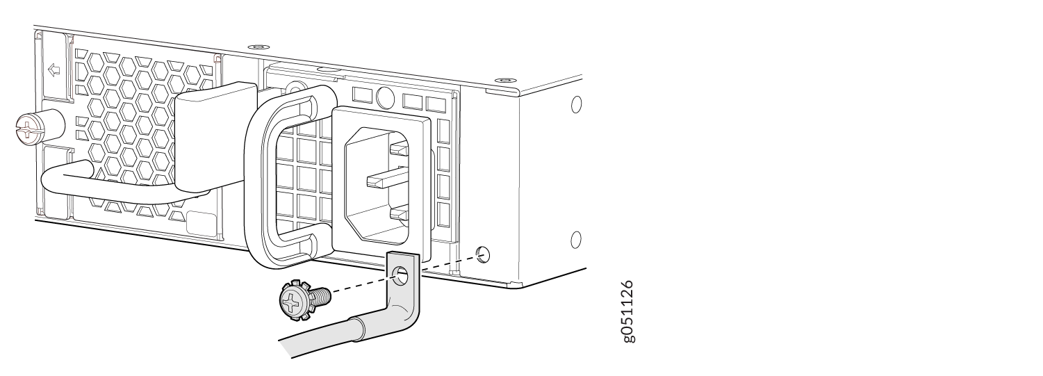 Figure 2: Connect a Grounding Cable to the QFX5120-48T or QFX5120-48Y
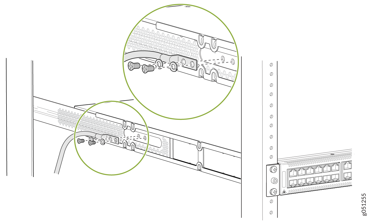 Figure 3: Connect a Grounding Cable to the Protective Earthing Terminal in the Rear of the Left Panel on the QFX5120-48YM Mounted on Four Posts
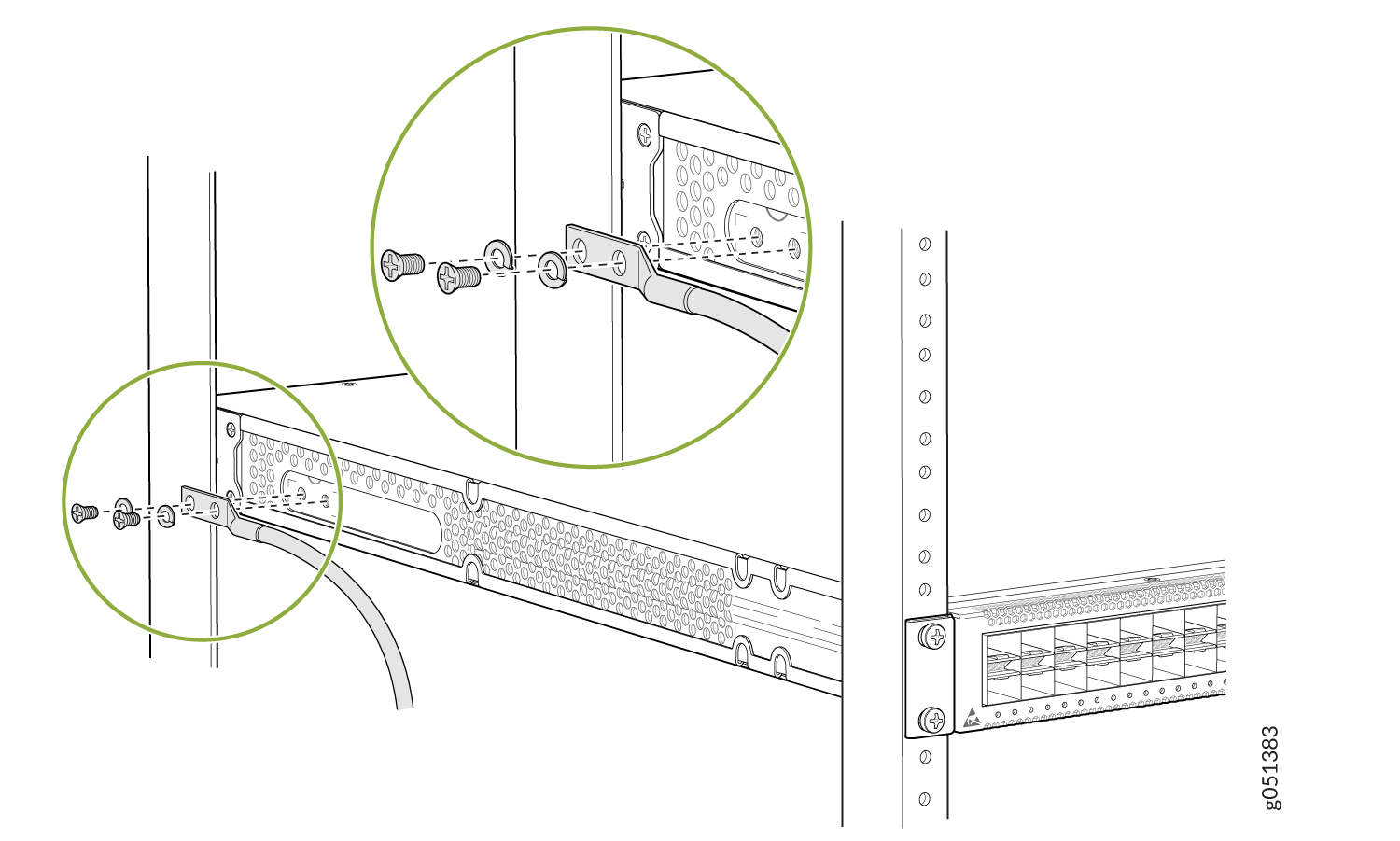 Figure 4: Connect a Grounding Cable to the Protective Earthing Terminal in the Front of the Left Panel on the QFX5120-48YM Mounted on Four Posts
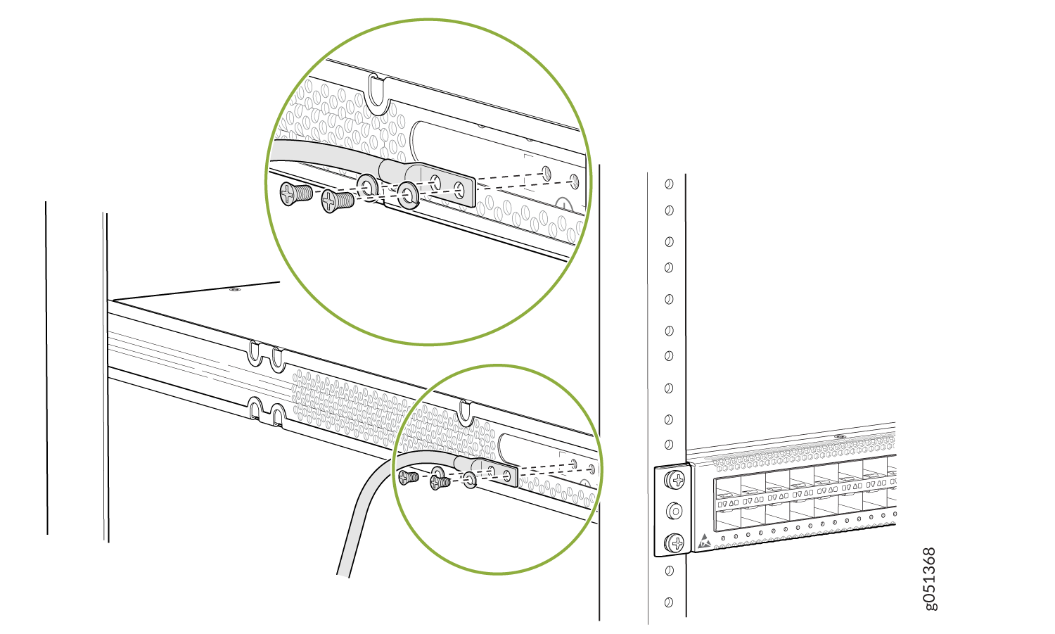 Figure 5: Connect a Grounding Cable to the Protective Earthing Terminal in the Rear of the Left Panel on the QFX5120-48YM Mounted on Two Posts
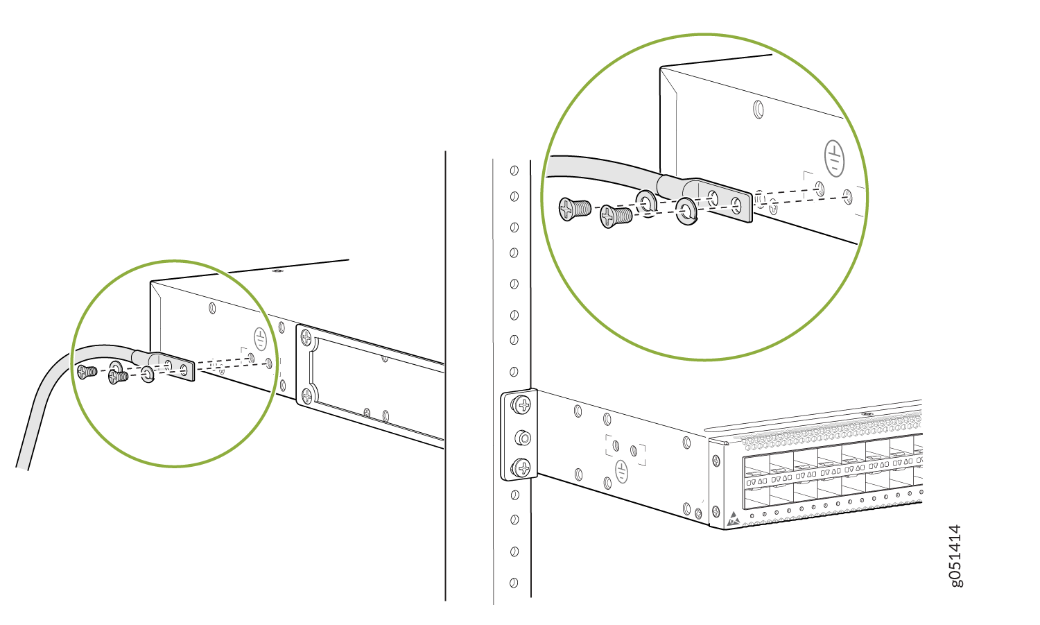 Figure 6: Connect a Grounding Cable to the Protective Earthing Terminal in the Front of the Left Panel on the QFX5120-48YM Mounted on Two Posts
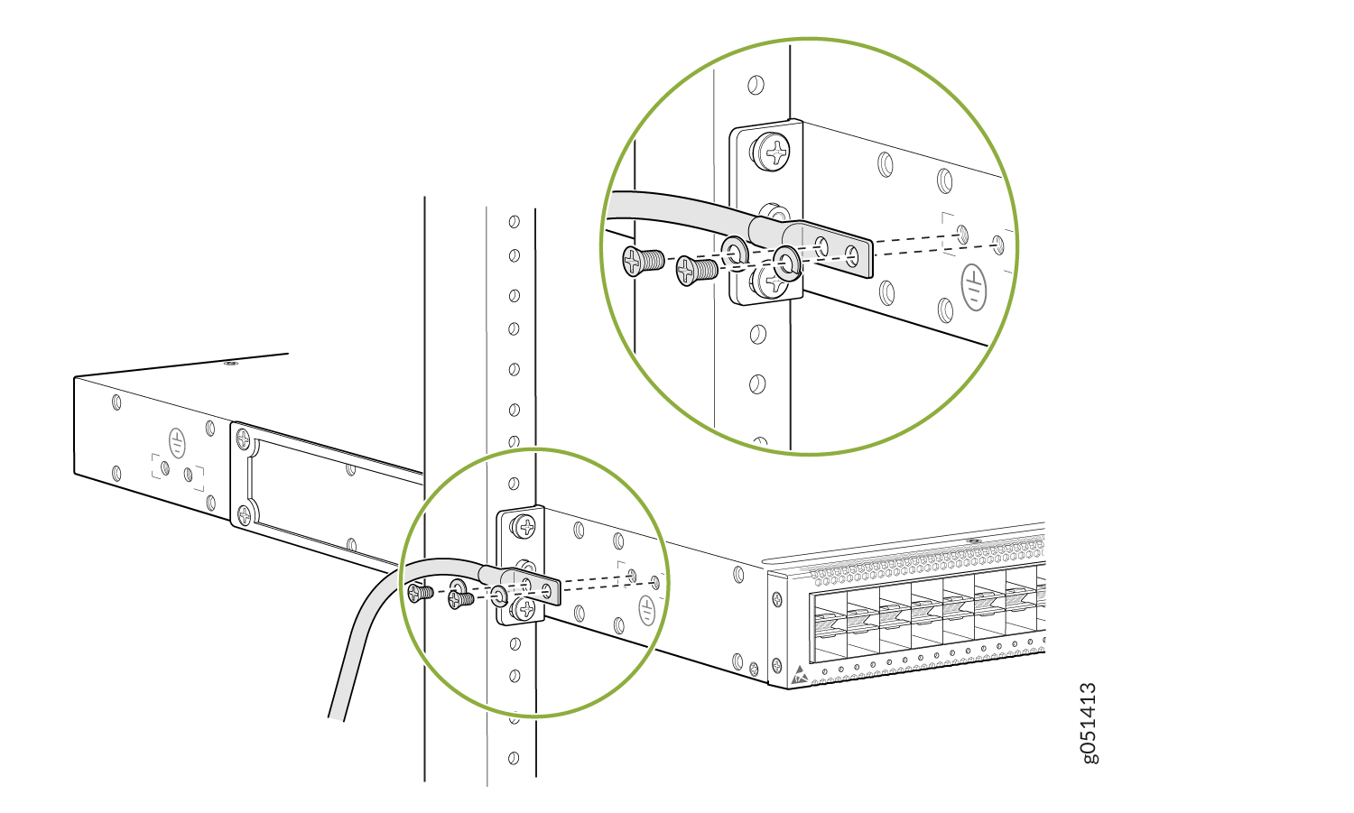
Connect Power to an AC-Powered QFX5120 Switch
Before you connect AC power to the switch:
Ensure that you have a power cord appropriate for your geographical location available.
Ensure that you have the power cord retainer shipped with the switch.
Ensure that you have taken the necessary precautions to prevent electrostatic discharge (ESD) damage (see Prevention of Electrostatic Discharge Damage).
Ensure that you have connected the switch chassis to earth ground.
CAUTION:Before you connect power to the switch, a licensed electrician must attach a cable lug to the grounding and power cables that you supply. A cable with an incorrectly attached lug can damage the switch (for example, by causing a short circuit).
To meet safety and electromagnetic interference (EMI) requirements and to ensure proper operation, you must connect the chassis to earth ground before you connect it to power (see Connect the QFX5120 Switch to Earth Ground). For installations that require a separate grounding conductor to the chassis, use the protective earthing terminal on the switch chassis to connect to earth ground. The switch gains additional grounding when you plug the power supply in the switch into a grounded AC power outlet by using the AC power cord appropriate for your geographical location.
We ship the QFX5120 switches with two power supplies preinstalled. Each power supply is a hot-removable and hot-insertable field-replaceable unit (FRU) when the second power supply is installed and running: You can remove and replace them without powering off the switch or disrupting switch functions.
To connect power to an AC-powered QFX5120 switch:
- Connect the power cord.
For QFX5120-32C, QFX5120-48T, and QFX5120-48Y switches:
Push the end of the retainer strip into the hole next to the inlet on the power supply faceplate until it snaps into place. Ensure that the loop in the retainer strip faces the power cord.
Press the small tab on the retainer strip to loosen the loop. Slide the loop until you have enough space to insert the power cord coupler into the inlet.
Insert the power cord coupler firmly into the inlet.
Slide the loop toward the power supply until it is snug against the base of the coupler.
Press the tab on the loop and draw out the loop into a tight circle (see Figure 7 and Figure 8).
Figure 7: Connect Power Cord to an AC-Powered QFX5120-32C Switch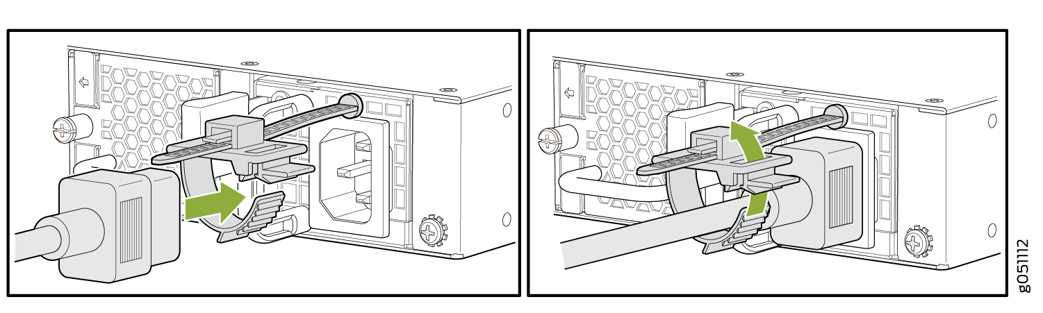 Figure 8: Connect Power Cord to an AC-Powered QFX5120-48T or QFX5120-48Y Switch
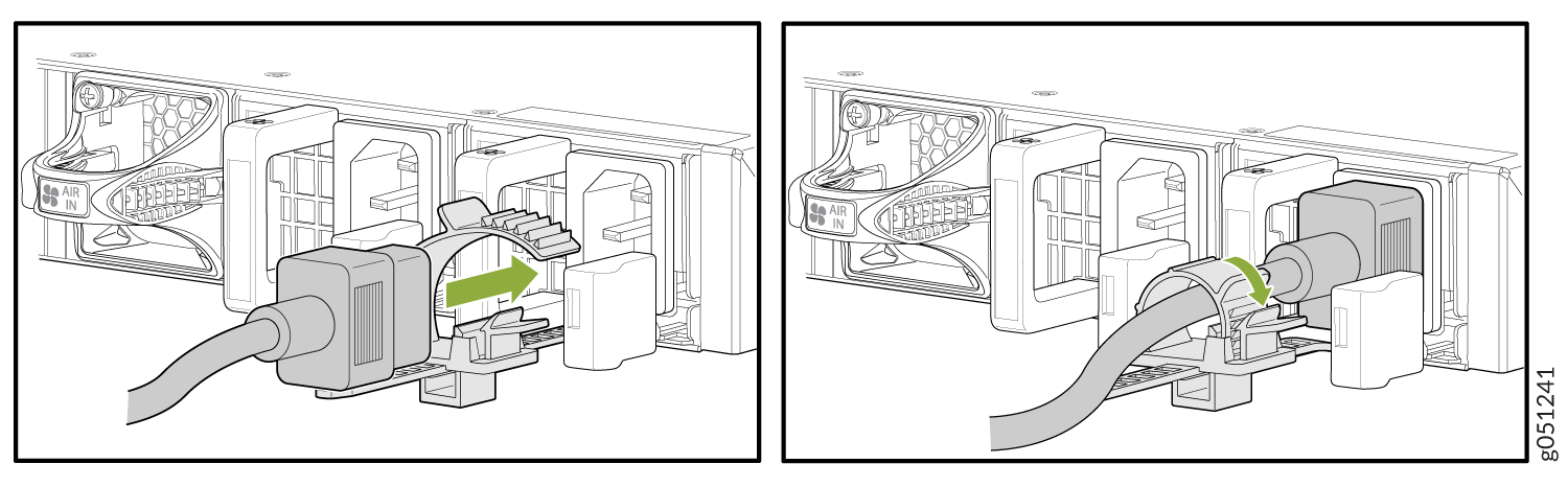
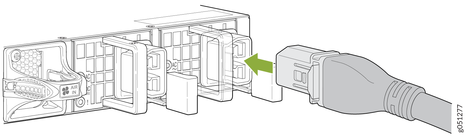
For QFX5120-48YM switches:
Gently lift the retainer clip up.
Insert the power cord coupler firmly into the inlet.
Push the retainer clip down until it is snug against the base of the coupler (see Figure 9).
Figure 9: Connect Power to an AC-Powered QFX5120-48YM Switch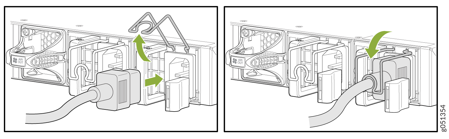
Connect Power to a DC-Powered QFX5120 Switch
Before you connect DC power to the switch:
-
Ensure that you have taken the necessary precautions to prevent electrostatic discharge (ESD) damage (see Prevention of Electrostatic Discharge Damage).
-
Ensure that you have connected the switch chassis to earth ground (see Connect the QFX5120 Switch to Earth Ground).
CAUTION:Before you connect power to the switch, a licensed electrician must attach a cable lug to the grounding and power cables that you supply. A cable with an incorrectly attached lug can damage the switch (for example, by causing a short circuit).
To meet safety and electromagnetic interference (EMI) requirements and to ensure proper operation, you must connect the chassis to earth ground before you connect it to power. For installations that require a separate grounding conductor to the chassis, use the protective earthing terminal on the switch chassis to connect to the earth ground.
Ensure that you have the following parts and tools available:
-
For the DC-powered models QFX5120-32C-DC-AFO and QFX5120-32C-DC-AFI: DC power cable with a plug—provided
-
For the DC-powered models QFX5120-48T-DC-AFO, QFX5120-48T-DC-AFI, QFX5120-48Y-DC-AFO2, and QFX5120-48Y-DC-AFI2: DC power source cables (14–16 AWG) with ring lug (Molex 190700069 or equivalent)—not provided
-
For the DC-powered models QFX5120-48YM-DC-AO and QFX5120-48YM-DC-AI: DC power source cables (14–12 AWG) with ring lug (Molex 190700069 or equivalent)—not provided
-
Number 2 Phillips (+) screwdriver—not provided
-
Multimeter—not provided
We ship the QFX5120 switches with two power supplies preinstalled. Each power supply is a hot-removable and hot-insertable field-replaceable unit (FRU) when the second power supply is installed and running: You can install power supplies in the slots next to the fan modules without powering off the switch or disrupting switch functions.
The battery returns of the DC power supply must be connected as an isolated DC return (DC-I).
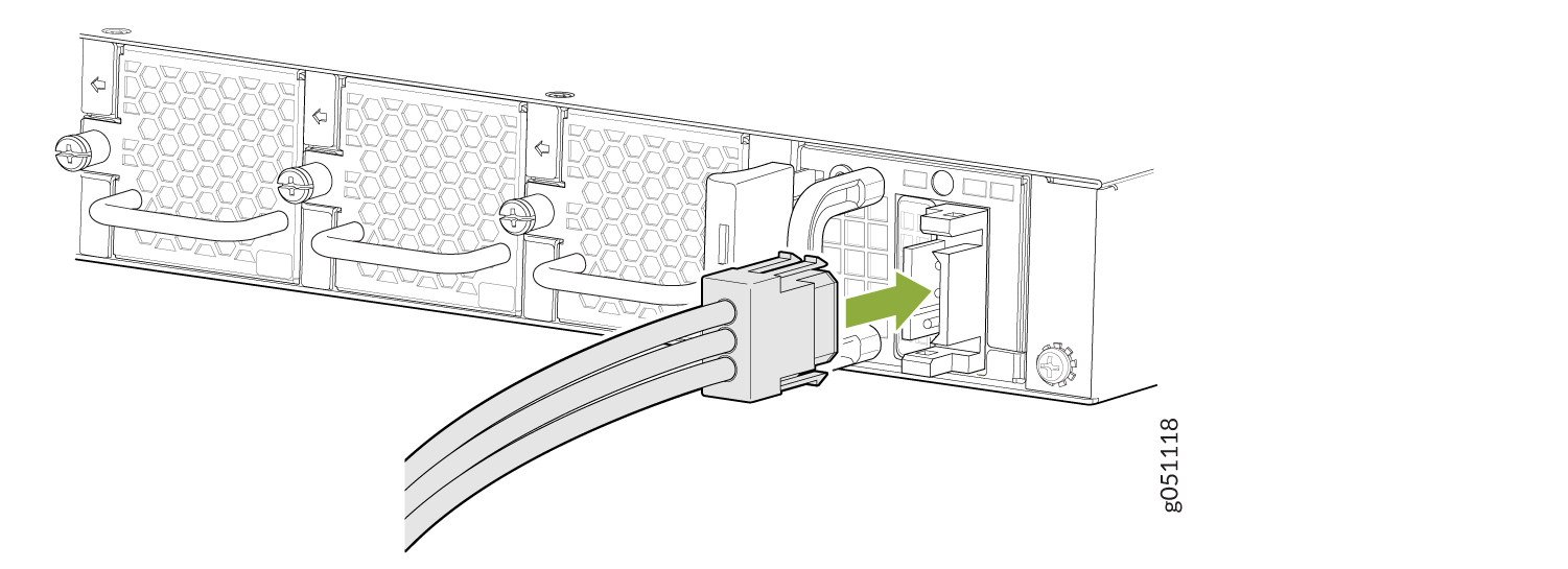
To connect power to a DC-powered QFX5120-32C switch:
-
Connect each power supply to the power source by inserting
the DC connector of the power cable provided into the power supply
(see Figure 10).
Figure 10: Connect Power to a DC-Powered QFX5120-32C Switch
To connect power to a DC-powered QFX5120-48T, QFX5120-48Y, or QFX5120-48YM switch:
-
Wrap and fasten one end of the ESD wrist strap around your bare wrist, and connect the other end of the strap to a site ESD point.
-
Verify that the DC power cables are correctly labeled before making connections to the power supply. In a typical power distribution scheme where the return is connected to chassis ground at the battery plant, you can use a multimeter to verify the resistance of the –48V and RTN DC cables to chassis ground:
-
The cable with very low resistance (indicating a closed circuit) to chassis ground is positive (+) and will be installed on the V+ (return) DC power input terminal.
-
The cable with very high resistance (indicating an open circuit) to chassis ground is negative (–) and will be installed on the V– (input) DC power input terminal.
CAUTION:You must ensure that power connections maintain the proper polarity. The power source cables might be labeled (+) and (–) to indicate their polarity. There is no standard coding for DC power cables. The coding used by the external DC power source at your site determines the coding for the leads on the power cables that attach to the DC power input terminals on each power supply.
-
-
Install heat-shrink tubing insulation around the power cables.
To install heat-shrink tubing:
-
Slide the tubing over the portion of the cable where it is attached to the lug barrel. Ensure that tubing covers the end of the wire and the barrel of the lug attached to it.
-
Shrink the tubing with a heat gun. Ensure that you heat all sides of the tubing evenly so that it shrinks around the cable tightly.
Figure 11 shows the steps to install heat-shrink tubing.
Note:Do not overheat the tubing.
Figure 11: How to Install Heat-Shrink Tubing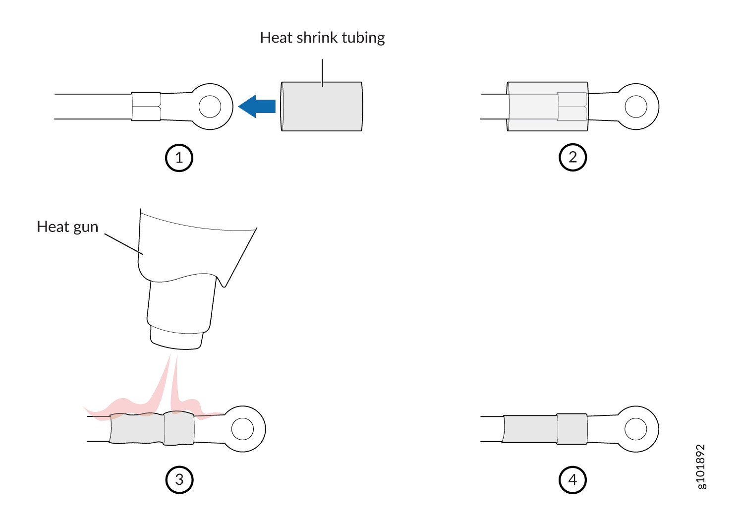
-
-
Ensure that the input circuit breaker is open so that the voltage across the DC power source cable leads is 0 V and that the cable leads do not become active while you are connecting DC power.
Note:The V+ terminals are referred to as +RTN, and the V– terminals are referred to as –48 V in DC Power Wiring Sequence Warning and DC Power Electrical Safety Guidelines.
-
Ensure that the power supplies are fully inserted in the chassis.
-
Remove the terminal block cover. The terminal block cover is a piece of clear plastic that snaps into place over the terminal block.
-
Remove the screws on the terminals using the screwdriver. Save the screws.
Warning:Ensure that the power cables do not block access to device components or drape where people can trip on them.
-
Connect each power supply to the power sources. Secure power source cables to the power supplies by screwing the ring lugs attached to the cables to the appropriate terminals by using the screw from the terminals (see Figure 12).
We’ve designed the QFX5120-48T, QFX5120-48Y, and QFX5120-48YM switches to operate with a DC power supply that has a single, nonredundant, feed input. For source redundancy, you must install two DC power supplies in the QFX5120-48T, QFX5120-48Y, and QFX5120-48YM switches; and then connect source (A) to one power supply and connect source (B) to the second power supply. This configuration provides the commonly deployed A/B feed redundancy for the system.
The terminal block of the power supply has four terminals labeled V+, V+, V–, and V– for connecting DC power source cables labeled positive (+) and negative (–). The V+ terminals are shunted internally together, as are the V– terminals.
CAUTION:The connection between each power source and power supply must include a circuit breaker.
Do not connect two sources to a single power supply because doing so can potentially cause circulating current in feed wires whenever there is any difference in the voltage of the two sources.
-
Secure the ring lug of the positive (+) DC power source cable to the V+ terminal on the DC power supply.
-
Secure the ring lug of the negative (–) DC power source cable to the V– terminal on the DC power supply.
-
Tighten the screws on the power supply terminals until snug using the screwdriver. Do not overtighten; apply between 5 lb-in. (0.56 Nm) and 6 lb-in. (0.68 Nm) of torque on the screws.
CAUTION:The V+ terminals are shunted internally together, as are the V- terminals. The same polarity terminal can be wired together from the same source to provide an additional current path in a higher power chassis. Do not connect the terminals to different sources.
Figure 12: Secure Ring Lugs to the Terminals on the QFX5120-48T, QFX5120-48Y, or QFX5120-48YM DC Power Supply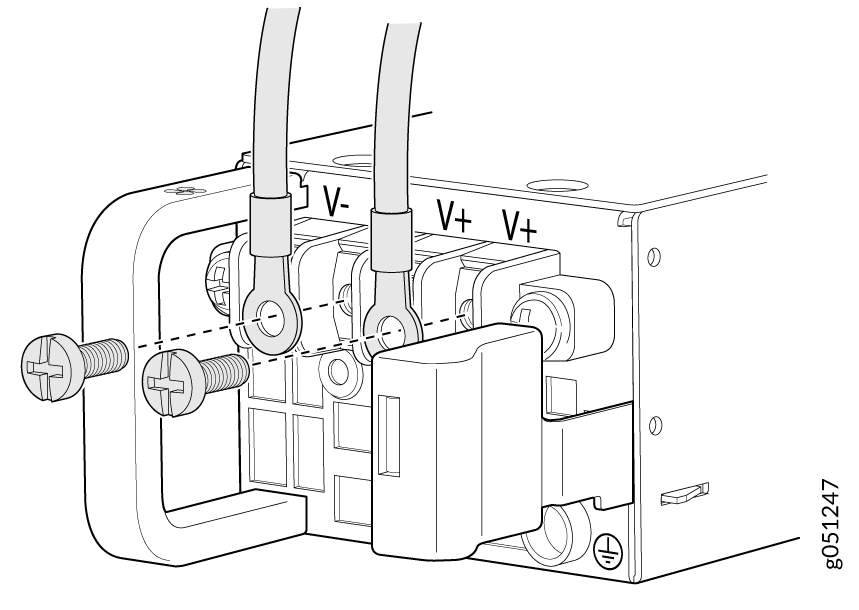
-
-
Replace the terminal block cover.
-
Close the input circuit breaker.
Note:The QFX5120 switch powers on as soon as power is provided to the power supply. There is no power switch on the QFX5120.
-
Verify that the IN and OUT LEDs on the power supply are lit green. If the fault LED (!) is lit, disconnect the power supply from the power source, and replace the power supply (see Remove a Power Supply from a QFX5120 Switch).
CAUTION:Do not remove the power supply until you have a replacement power supply ready: you must install the replacement power supply within one minute after removing the failed power supply to ensure proper airflow and prevent chassis overheating.
Connect Power to a QFX5120-48T Switch Powered by a High-Voltage Power Supply
Before you connect power to a QFX5120-48T switch powered by a high-voltage power supply:
-
Ensure that you have a power cord appropriate for your geographical location and power input available. You must order the power cord separately.
-
Ensure that you have taken the necessary precautions to prevent electrostatic discharge (ESD) damage (see Prevention of Electrostatic Discharge Damage).
-
Ensure that you have connected the switch chassis to earth ground.
CAUTION:Before you connect power to the switch, a licensed electrician must attach a cable lug to the grounding and power cables that you supply. A cable with an incorrectly attached lug can damage the switch (for example, by causing a short circuit).
To meet safety and electromagnetic interference (EMI) requirements and to ensure proper operation, you must connect the chassis to earth ground before you connect it to power (see Connect the QFX5120 Switch to Earth Ground). For installations that require a separate grounding conductor to the chassis, use the protective earthing terminal on the switch chassis to connect to earth ground. The switch gains additional grounding when you plug the power supply in the switch into a grounded AC power outlet by using the AC power cord appropriate for your geographical location.
We ship the QFX5120 switches with two 650-W AC or DC power supplies preinstalled. You must order a high-voltage power supply separately. Each power supply is a hot-removable and hot-insertable field-replaceable unit (FRU) when the second power supply is installed and running: You can remove and replace them without powering off the switch or disrupting switch functions.
To connect power to a QFX5120-48T switch powered by a high-voltage power supply:
-
Insert the coupler end of the power cord into the power
cord inlet on the power supply faceplate (see Figure 13).
Figure 13: Connect Power to a QFX5120-48T Switch Powered by a High-Voltage Power Supply
 Note:
Note:The QFX5120 switch powers on as soon as power is provided to the power supply. There is no power switch on the QFX5120.