Maintain the QFX5120 Power System
Remove a Power Supply from a QFX5120 Switch
Before you remove a power supply from a QFX5120 switch:
-
Ensure that you have taken the necessary precautions to prevent electrostatic discharge (ESD) damage (see Prevention of Electrostatic Discharge Damage).
-
Ensure that you have the following parts and tools available:
-
ESD grounding strap—not provided
-
Antistatic bag or an antistatic mat—not provided
-
Number 2 Phillips (+) screwdriver—not provided
-
We ship QFX5120 switches with two AC or DC power supplies preinstalled in the rear panel. Each power supply is a hot-removable and hot-insertable field-replaceable unit (FRU) when the second power supply is installed and running. You can remove and replace it without powering off the switch or disrupting switch functions.
Replace the power supply with a new power supply within one minute of removal to prevent chassis overheating.
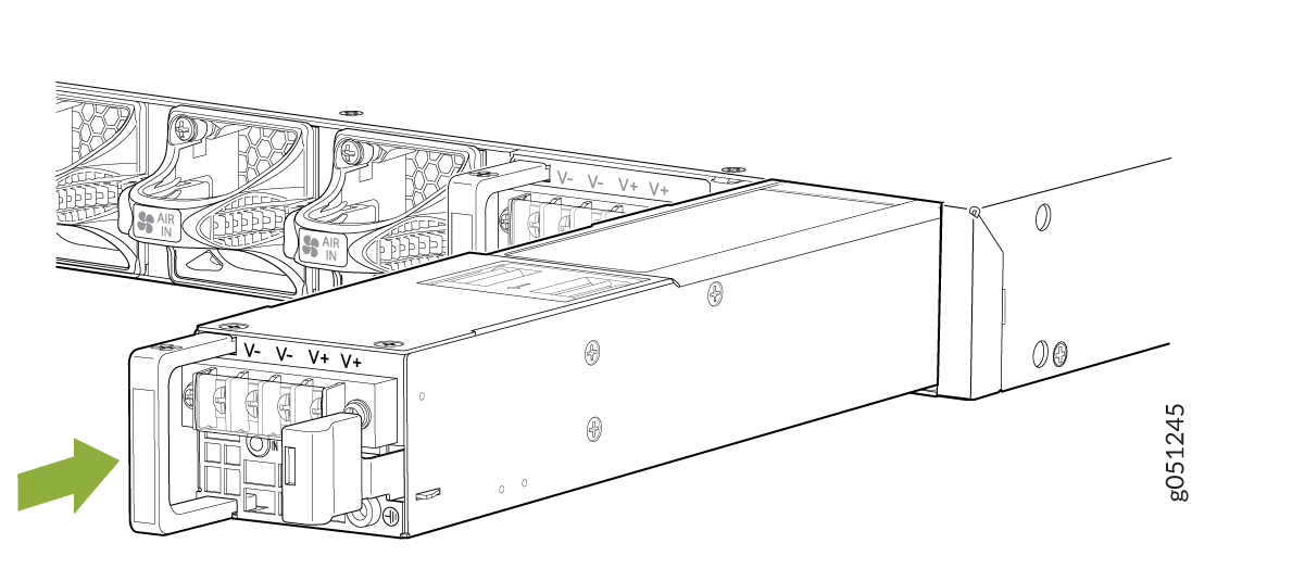
To remove a power supply from a QFX5120 switch:
-
Place one hand under the power supply to support it and
slide it completely out of the chassis. Take care not to touch power
supply components, pins, leads, or solder connections.
Figure 1 shows how to remove an AC power supply from a QFX5120-32C switch and Figure 2 shows how to remove a DC power supply from a QFX5120-32C switch.
Figure 3 shows how to remove an AC power supply from a QFX5120-48T or QFX5120-48Y switch. The procedure to remove a high-voltage power supply is the same as the procedure to remove a power supply from a QFX5120-48T switch. Figure 4 shows how to remove an AC power supply from a QFX5120-48YM switch. Figure 5 shows how to remove a DC power supply from a QFX5120-48T, QFX5120-48Y, or QFX5120-48YM switch.
Figure 1: Remove an AC Power Supply from a QFX5120-32C Switch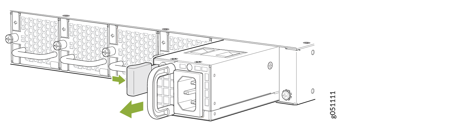 Figure 2: Remove a DC Power Supply from a QFX5120-32C Switch
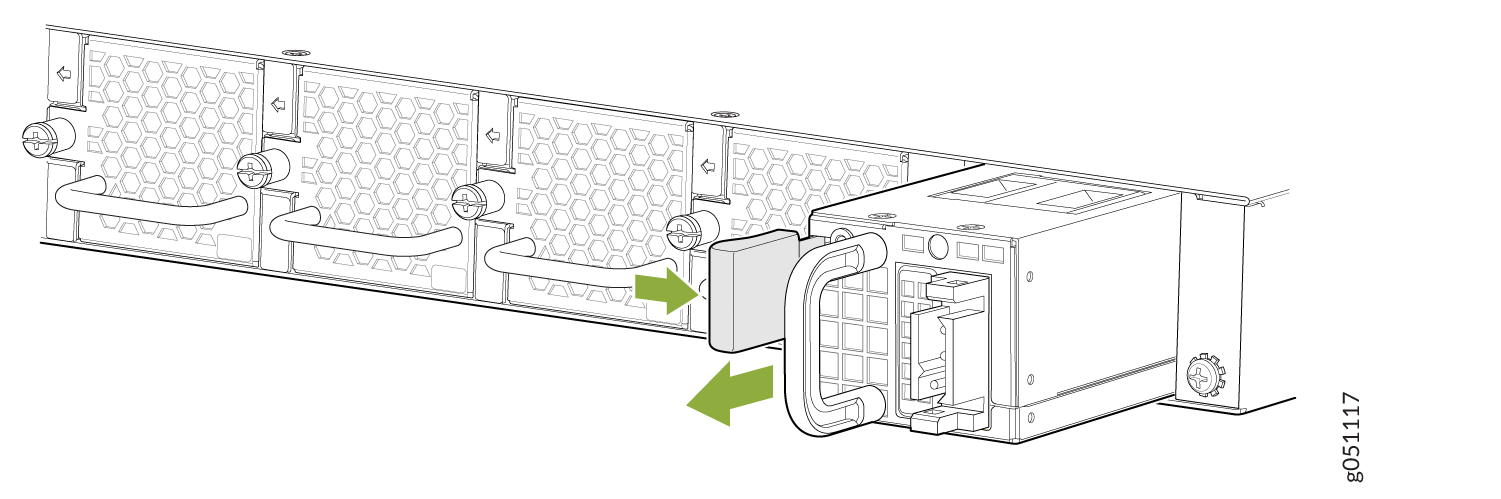 Figure 3: Remove an AC Power Supply from a QFX5120-48T or QFX5120-48Y Switch
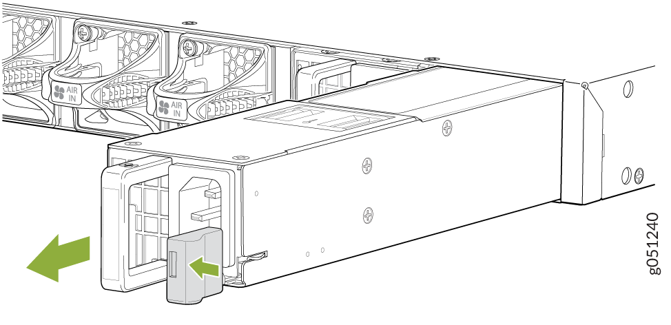 Figure 4: Remove an AC Power Supply from a QFX5120-48YM Switch
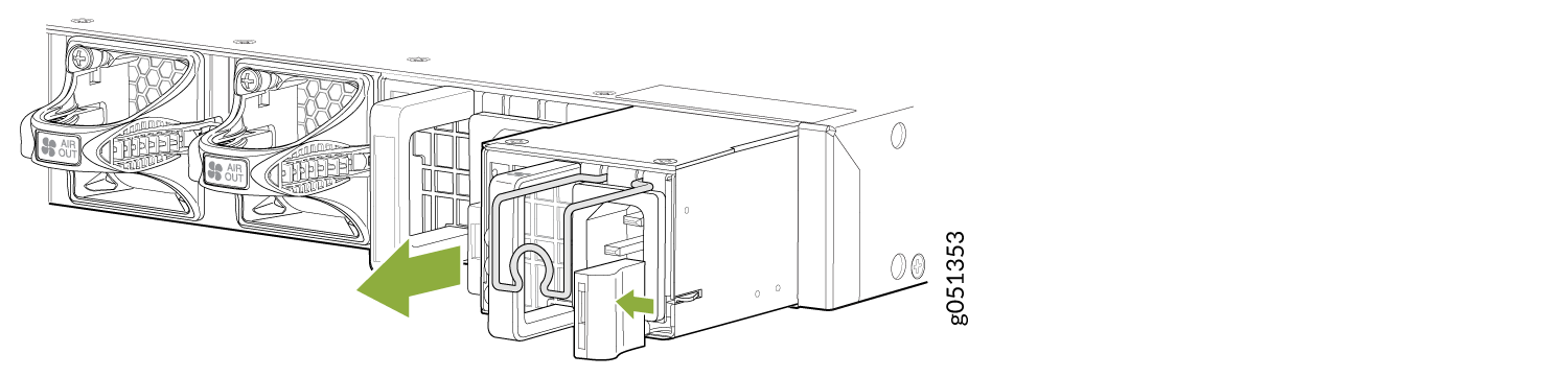 Figure 5: Remove a DC Power Supply from a QFX5120-48T, QFX5120-48Y, or QFX5120-48YM Switch
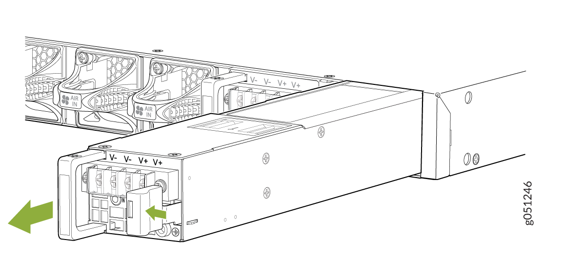
Install a Power Supply in a QFX5120 Switch
Before you install a power supply:
-
Ensure that you understand how to prevent electrostatic discharge (ESD) damage (see Prevention of Electrostatic Discharge Damage).
-
Ensure that you have the following parts and tools available:
-
ESD grounding strap—not provided
-
Number 2 Phillips (+) screwdriver—not provided
-
Each power supply is a hot-removable and hot-insertable field-replaceable unit (FRU) when the second power supply is installed and running. You can remove and replace it without powering off the switch or disrupting switch functions.
Do not mix:
-
AC and DC power supplies in the same chassis.
-
650-W and 850-W power supplies in the same QFX5120-48T chassis.
-
Power supplies with different airflow directions in the same chassis.
-
Power supplies and fan modules with different airflow directions in the same chassis.
You must connect each power supply to a dedicated power source outlet.
To install a power supply in the switch:
-
Using both hands, place the power supply in the power
supply slot on the rear panel of the switch and slide it in until
it is fully seated and the ejector lever fits into place.
Figure 6 shows how to install an AC power supply in a QFX5120-32C switch and Figure 7 shows how to install a DC power supply in a QFX5120-32C switch.
Figure 8 shows how to install an AC power supply in a QFX5120-48T or QFX5120-48Y switch. The procedure to install a high-voltage power supply is the same as the procedure to install an AC power supply in a QFX5120-48T switch. Figure 9 shows how to install an AC power supply in a QFX5120-48YM switch. Figure 10 shows how to install a DC power supply in a QFX5120-48T, QFX5120-48Y, or QFX5120-48YM switch.
Figure 6: Install an AC Power Supply in a QFX5120-32C Switch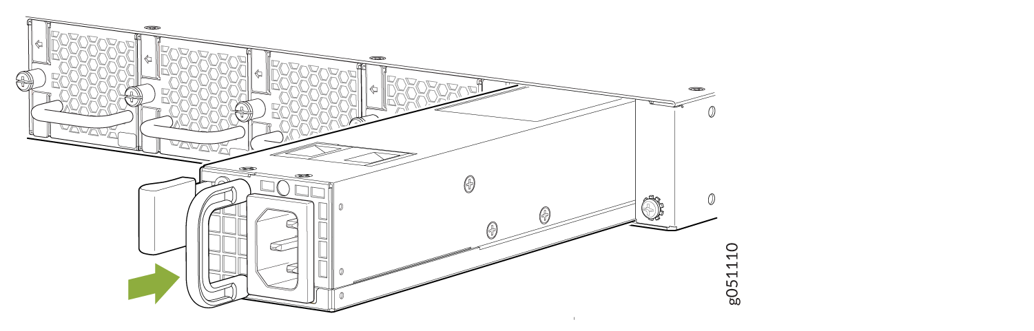 Figure 7: Install a DC Power Supply in a QFX5120-32C Switch
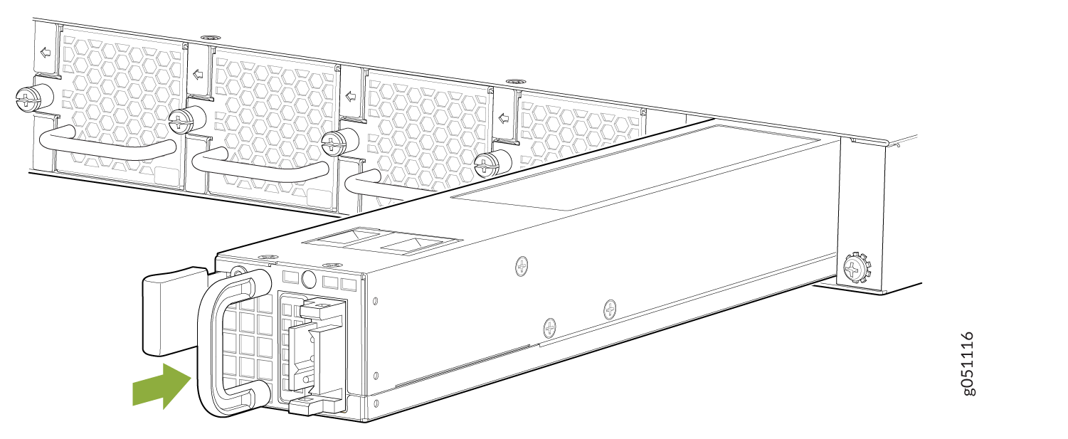 Figure 8: Install an AC Power Supply in a QFX5120-48T or QFX5120-48Y Switch
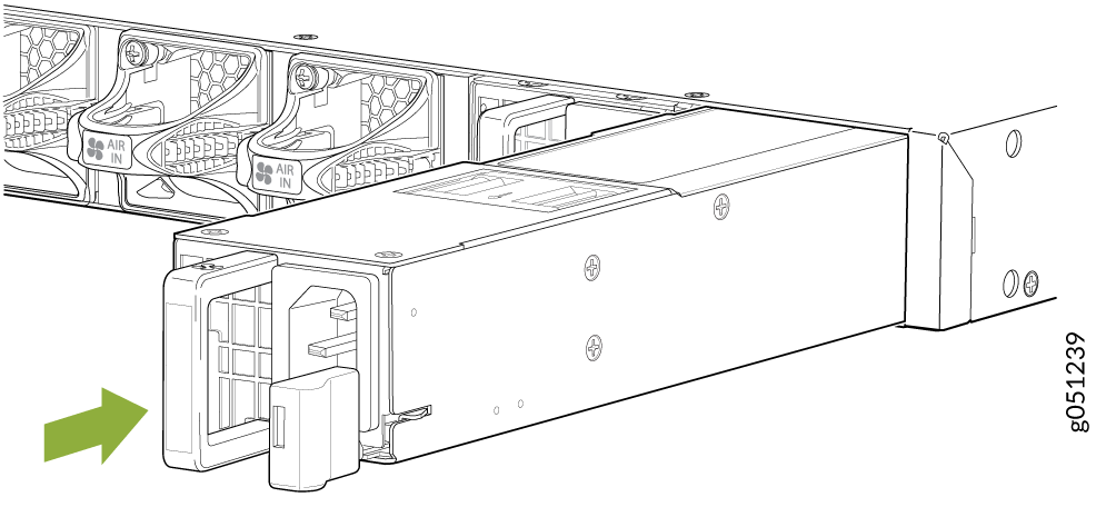 Figure 9: Install an AC Power Supply in a QFX5120-48YM Switch
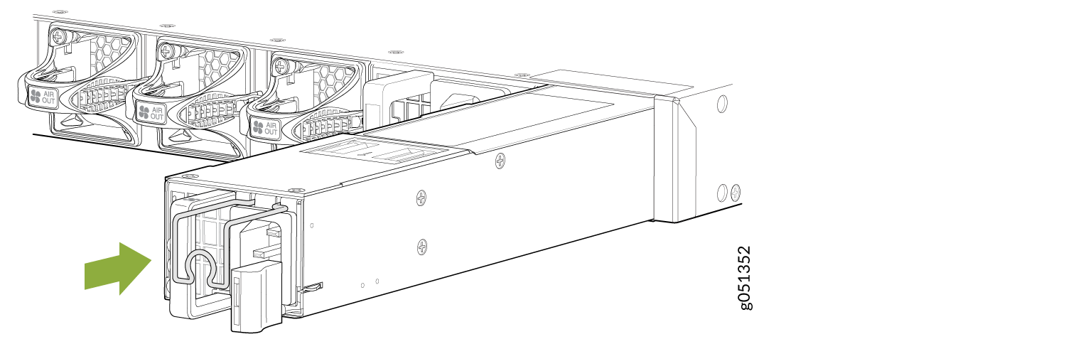 Figure 10: Install a DC Power Supply in a QFX5120-48T, QFX5120-48Y, or QFX5120-48YM Switch