Help us improve your experience.

Let us know what you think.

Do you have time for a two-minute survey?


Removing the QFX10016

Powering Off a QFX10000

Before you power off a QFX10000:

Note:

Use the following procedure to power off a QFX10000.

Ensure that you have the following parts and tools available to power off the switch:

  • An ESD grounding strap

  • An external management device such as a PC

  • An RJ-45 to DB-9 rollover cable to connect the external management device to the console port on one of the Routing and Control Board (RCBs)

To power off a QFX10000:

  1. Connect to the switch using one of the following methods:
  2. Shut down Junos OS from the external management device by issuing the request system halt operational mode CLI command. This command shuts down the switch gracefully and preserves system state information. A message appears on the console, confirming that the operating system has halted.

    You see the following output (or something similar, depending on the hardware being shut down) after entering the command:

    CAUTION:

    The final output of any version of the request system halt command is the “The operating system has halted.” Wait at least 60 seconds after first seeing this message before following the instructions in Step 4 and Step 5 to power off the switch.

  3. Attach the grounding strap to your bare wrist and to one of the two site ESD points on the chassis.
  4. Disconnect power to the switch by performing one of the following tasks:
    • AC power supply—Set the enable switch to the OFF (O) position and gently pull out the coupler for the power cord from the faceplate.

    • DC power supply—Switch the circuit breaker on the panel board that services the DC circuit to the OFF position.

  5. Remove the power source cable from the power supply faceplate:
    • AC power supply—Remove the power cord from the power supply faceplate by detaching the power cord retainer and gently pulling out the plug end of the power cord connected to the power supply faceplate.

    • DC power supply—Loosen the thumbscrews securing the DC power connector on the power source cables. Remove the power source cables from the power supply.

  6. Remove any remaining cables and optics from the switch before removing it from the rack.

Removing a QFX10016 From a 4-Post Rack Using a Mechanical Lift

Before you remove the switch using a lift:

CAUTION:

When removing more than one switch chassis from a rack, remove the switches in order from top to bottom.

Ensure that you have the following parts and tools available to remove the switch:

  • A mechanical lift rated for 1000 lbs. (453.6 kg)

  • A Phillips (+) screwdriver, number 2 or number 3, depending on the size of your rack-mounting screws

Because of the switch's size and weight, we only recommend using a mechanical lift to install the QFX10016.

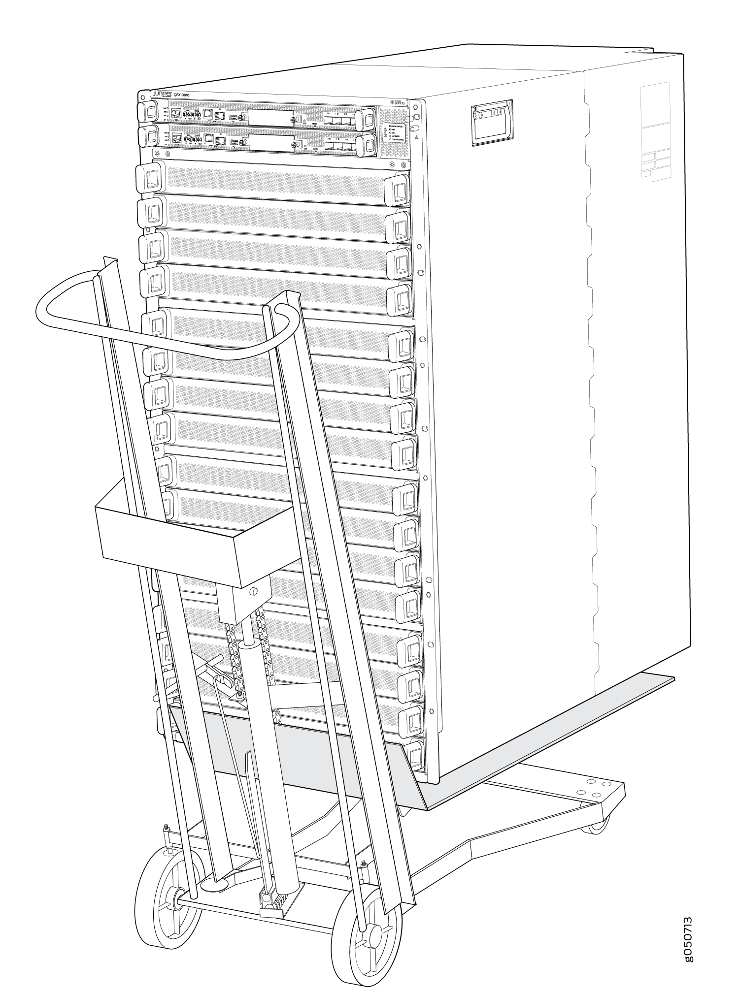
To remove the switch using a mechanical lift (see Figure 1):

  1. Use the appropriate Phillips (+) screwdriver to remove the 12 mounting screws that attach the chassis front-mounting brackets to the rack.
  2. Move the lift to the rack and position it so that its platform is centers about 0.5 in. (1.27 cm) below the bottom of the switch chassis and as close to it as possible.
  3. Carefully slide the switch from the adjustable mounting brackets attached to the rack onto the lift.
  4. Move the lift away from the rack and lower the lift.
  5. Use the lift to transport the switch to its new location.
    Figure 1: Moving the QFX10016 Using a Mechanical LiftMoving the QFX10016 Using a Mechanical Lift