QFX10000 Line Cards
QFX10000-30C Line Card
The QFX10000-30C line card consists of thirty 28-Gbps QSFP+ Pluggable Solution (QSFP28) cages that support 40-Gigabit Ethernet or 100-Gigabit Ethernet optical transceivers. The QFX10000-30C ports automatically detect the type of transceiver installed and set the configuration to the appropriate speed. The line card can support 10-Gigabit Ethernet by channelizing the 40-Gigabit ports. Channelization is supported on fiber breakout cable using standard structured cabling techniques.
The QFX10000-30C line card is supported on Junos OS Release 15.1X53-D30 and later. Support for channelizing the 40-Gigabit Ethernet ports to four independent 10-Gigabit Ethernet ports is supported in Junos OS Release 17.1R1 and later.
This topic describes:
Overview
The line cards in QFX10000 modular switches combine a Packet Forwarding Engine and Ethernet interfaces in a single assembly. Line cards are field-replaceable units (FRUs) that can be installed in the line card slots on the front of the switch chassis. The line cards are hot-insertable and hot-removable; you can remove and replace them without powering off the switch or disrupting switch functions. See Figure 1.
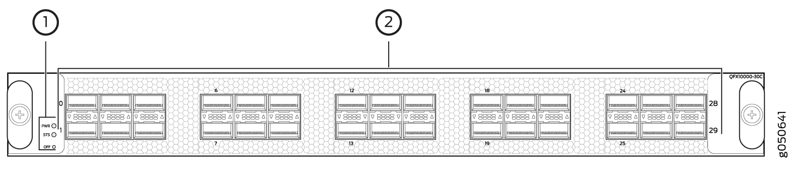
1 — Power and status LEDs | 2 — Network ports |
Channelizing 40-Gigabit Ports
Beginning with Junos OS Release 17.1R1, 40-Gigabit Ethernet ports on the QFX10000-30C line card can be channelized to 10-Gigabit Ethernet. When ports are in channelization mode, every fourth port is disabled. See Figure 2 to see which ports are disabled and see Table 1 for the maximum port configurations.

Port Speed |
Non-Channelized Mode (Mode D) |
Channelized Mode (Mode A) |
|---|---|---|
100 Gbps |
30 or |
24 or |
40 Gbps |
30 |
24 or |
10 Gbps |
0 |
96 |
Unlike the QFX10000-36C line card, the QFX10000-30C line card does not have port groups; instead, port behavior is tied to the ASIC associated with the port. You must configure each port individually, in order to channelize a 40-Gigabit Ethernet port to 4 independent 10-Gigabit Ethernet ports. The first time a port for an associated ASIC is changed from the default configuration mode (mode D) to the channelization mode (mode A), the FPC reboots. Subsequent channelization of the ports for that ASIC does not cause the FPC to reboot. However if the last channelized port is changed back to the default configuration mode, the FPC will again reboot. See Table 2 for the list of available ports and the associated ASIC and Figure 2 to locate the available and disabled ports.
Changing the channelization mode (mode D to mode A or mode A to mode D) causes the FPC to reboot. Because there can be a slight loss of data while the FPC reboots, we recommend that you only configure the changes during a maintenance window.
ASIC |
Available Ports |
Disabled Port |
|---|---|---|
PE0 |
0, 2, 4, 6, 8 |
6 |
PE1 |
1, 3, 5, 7, 9 |
7 |
PE2 |
10, 12, 14, 16, 18 |
16 |
PE3 |
11, 13, 15, 17, 19 |
17 |
PE4 |
20, 22, 24, 26, 28 |
26 |
PE5 |
21, 23, 25, 27, 29 |
27 |
To change from the default mode to 40-Gigabit Ethernet channelized mode, use the Junos OS operational command set chassis fpc slot-number pic 0 port port number channel-speed 10g.
Switch Ports
Each of the 30 QSFP28 ports supports:
100-Gigabit Ethernet using QSFP28 optical transceivers. When a QSFP28 transceiver is inserted into any of the ports, the QSFP28 port is enabled for 100-Gigabit Ethernet.
40-Gigabit Ethernet using QSFP+ optical transceivers. When a QSFP+ transceiver is inserted into any of the ports, the QSFP+ port is enabled for 40-Gigabit Ethernet.
100-Gigabit Ethernet active optic cables (AOC)
QSFP28 direct attach copper (DAC) cables
QSFP+ DAC cables
QSFP+ to SFP+ direct attach copper breakout (DACBO) cables
Access ports—You can use 40-Gigabit Ethernet QSFP+ transceivers and QSFP+ DAC cables in any downstream port. See QFX10000 Optical Transceiver and Cable Support.
Uplink ports—You can configure all the QSFP28 ports as uplinks.
On the QFX10000-30C, the ports are enabled by default, and the default configuration adds the ports to the default VLAN.
Status and Activity LEDs
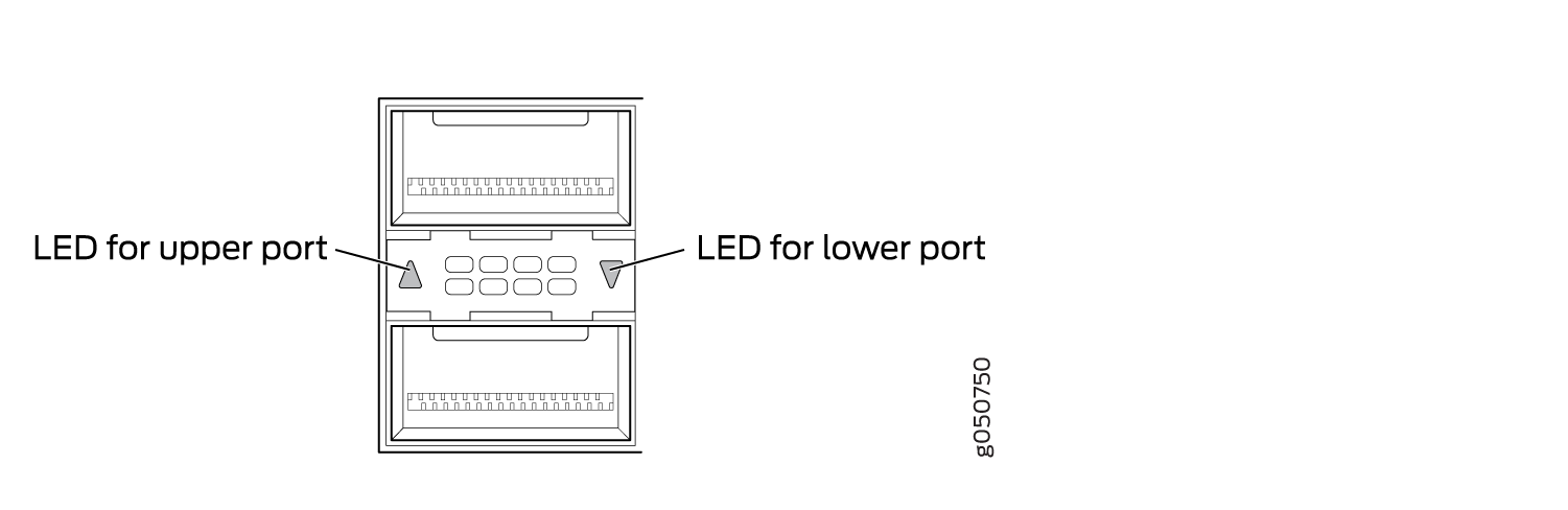
All QSFP28 ports have an up or down indicator for each port and four bi-colored LEDs that show port status and link activity based on whether or not the port is configured for channelization. See Figure 3 and Table 3.
Color |
State |
Description |
|---|---|---|
Unlit |
Off |
The port is administratively disabled, there is no power, the link is down, or a transceiver is not present. All sub-channels are disabled. |
Green |
On steadily |
A link is established. When channelized, all sub-channels are up. When not channelized, it indicates no activity. |
Blinking |
A link is up and there is activity. When not channelized, it indicates the port is up and active in either 40-Gigabit or 100-Gigabit mode. When channelized, all four channels are up and active. |
|
Yellow or Amber (channelized) |
On steadily |
At least one channel link is up, but not all channels are up. There is no activity on the channel link. |
Flashing |
At least one channel link is up, but not all channels are up. There is activity on the channel link. |
|
Slow blink, or blip |
The beacon function is enabled on one or more sub-channels. |
|
Blinking |
One or more sub-channels has a fault condition. |
|
Yellow or Amber (non-channelized) |
Blinking |
A single LED blinking indicates and interface fault. All four LEDs blink to indicate the beacon function was enabled on the port. |
See Also
QFX10000-30C-M Line Card
The QFX10000-30C-M line card is designed to provide secure Ethernet communication across high-speed links. The card consists of 30 ports of 28 Gbps QSFP+ Pluggable Solution (QSFP28) that are Media Access Control Security (MACsec) capable. The ports support speeds of 100 Gbps or 40 Gbps and can automatically detect the type of transceiver installed and set the configuration to the appropriate speed.
As part of Juniper Networks Open Cloud Interconnect, the QFX10000-30C-M line card brings secure data center interconnect (DCI), inter-data center and intra-data center connectivity using MACsec at 100 Gbps and 40 Gbps speeds. When configured for 40 Gigabit Ethernet, a QSFP28 port can breakout to 4 independent 10 small form-factor pluggable plus+ (SFP+) ports. MACsec provides point-to-point security on Ethernet links between directly connected nodes and is capable of identifying and preventing most security threats, including denial of service, intrusion, man-in-the-middle, masquerading, passive wiretapping, and playback attacks.
The QFX10000-30C-M line card is supported on Junos OS Release 17.4R1-S2 and later. Support for channelizing the 40-Gigabit Ethernet ports to four independent 10-Gigabit Ethernet ports is supported in Junos OS Release 19.2R1 and later.
This topic describes:
- Overview
- Channelizing 40-Gigabit Ports
- Network Ports
- Power and Status LEDs
- Port Status and Activity LEDs
Overview
The line cards in QFX10000 modular switches combine a Packet Forwarding Engine and Ethernet interfaces in a single assembly. Line cards are field-replaceable units (FRUs) that can be installed in the line card slots on the front of the switch chassis. The line cards are hot-insertable and hot-removable; you can remove and replace them without powering off the switch or disrupting switch functions. See Figure 4.
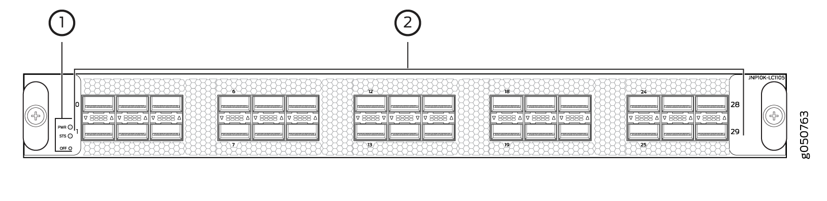
1 — Power LED, status LED, and offline button | 2 — Network ports |
Channelizing 40-Gigabit Ports
Beginning with Junos OS Release 18.2R1, 40-Gigabit Ethernet ports on the QFX10000-30C-M line card can be channelized to 10-Gigabit Ethernet. When ports are in channelization mode, every fourth port is disabled. See Figure 5 to see which ports are disabled and see Table 4 for the maximum port configurations.
Port Speed |
Non-Channelized Mode (Mode D) |
Channelized Mode (Mode A) |
|---|---|---|
100 Gbps |
30 or |
24 or |
40 Gbps |
30 |
24 or |
10 Gbps |
0 |
96 |
Unlike the QFX10000-36C line card, the QFX10000-30C-M line card does not have port groups; instead, port behavior is tied to the ASIC associated with the port. You must configure each port individually, in order to channelize a 40-Gigabit Ethernet port to 4 independent 10-Gigabit Ethernet ports. The first time a port for an associated ASIC is changed from the default configuration mode (mode D) to the channelization mode (mode A), the FPC reboots. Subsequent channelization of the ports for that ASIC does not cause the FPC to reboot. However if one of the channelized ports is changed back to the default, the FPC will again reboot. See Table 5 for the list of available ports and the associated ASIC and Figure 5 to locate the available and disabled ports.
Changing the channelization mode (mode D to mode A or mode A to mode D) causes the FPC to reboot. Because there can be a slight loss of data while the FPC reboots, we recommend that you only configure the changes during a maintenance window.
ASIC |
Available Ports |
Disabled Port |
|---|---|---|
PE0 |
0, 2, 4, 6, 8 |
6 |
PE1 |
1, 3, 5, 7, 9 |
7 |
PE2 |
10, 12, 14, 16, 18 |
16 |
PE3 |
11, 13, 15, 17, 19 |
17 |
PE4 |
20, 22, 24, 26, 28 |
26 |
PE5 |
21, 23, 25, 27, 29 |
27 |
To change from the default mode to 40-Gigabit Ethernet channelized mode, use the Junos OS operational command set chassis fpc slot-number pic 0 port port number channel-speed 10g.
Network Ports
Each of the 30 QSFP28 ports supports:
100-Gigabit Ethernet using QSFP28 optical transceivers. When a QSFP28 transceiver is inserted into any of the ports, the QSFP28 port is enabled for 100-Gigabit Ethernet.
40-Gigabit Ethernet using QSFP+ optical transceivers. When a QSFP+ transceiver is inserted into any of the ports, the QSFP+ port is enabled for 40-Gigabit Ethernet.
QSFP+ to SFP+ direct attach copper breakout (DACBO) cables
On the QFX10000-30C-M, the ports are enabled by default, and the default configuration adds the ports to the default VLAN.
Power and Status LEDs
The two LEDs to the left of the network ports indicate the power (PWR) and status (STS) for the line card. See Table 6 and Table 7.
Color |
State |
Description |
|---|---|---|
Unlit |
Off |
There is no power to the line card. |
Green |
On steadily |
The line card has power. |
Yellow or amber |
Blinking |
The line card has a power fault. |
Color |
State |
Description |
|---|---|---|
Unlit |
Off |
The line card is offline or disabled.. |
Green |
On steadily |
The line card is online. |
Yellow or amber |
On steadily |
The line card is booting. |
Blinking |
The line card has a fault condition or alarm. |
|
Slow blink or blip |
The beacon function is enabled. |
Port Status and Activity LEDs
Each QSFP28 port has a bi-colored up or down LED indicator that show port status and link activity. See Figure 6 and Table 8.
Color |
State |
Description |
|---|---|---|
Unlit |
Off |
The port is administratively disabled, there is no power, the link is down, or a transceiver is not present. All sub-channels are disabled. |
Green |
On steadily |
A link is established. When channelized, all sub-channels are up. When not channelized, it indicates no activity. |
Blinking |
A link is up and there is activity. When not channelized, it indicates the port is up and active in either 40-Gigabit or 100-Gigabit mode. When channelized, all four channels are up and active. |
|
Yellow or Amber (channelized) |
On steadily |
At least one channel link is up, but not all channels are up. There is no activity on the channel link. |
Flashing |
At least one channel link is up, but not all channels are up. There is activity on the channel link. |
|
Slow blink, or blip |
The beacon function is enabled on one or more sub-channels. |
|
Blinking |
One or more sub-channels has a fault condition. |
|
Yellow or Amber |
Blinking |
A single LED blinking indicates an interface fault. All four LEDs blink to indicate the beacon function was enabled on the port. |
See Also
QFX10000-36Q Line Card
The QFX10000-36Q line card consists of 36 quad small form-factor pluggable plus (QSFP+) ports that support 40-Gigabit Ethernet optical transceivers. Out of these 36 ports, 12 ports are QSFP28 capable. The QSFP28 capable ports are dual speed and can support either 40-Gigabit or 100-Gigabit Ethernet optical transceivers. The line card can support 10-Gigabit Ethernet by channelizing the 40-Gigabit ports. Channelization is supported on fiber breakout cable using standard structured cabling techniques.
The QFX10000-36Q line card is supported on Junos OS Release 15.1X53-D30 and later.
This topic describes:
Overview
The line cards in QFX10000 modular switches combine a Packet Forwarding Engine and Ethernet interfaces in a single assembly. Line cards are field-replaceable units (FRUs) that can be installed in the line card slots on the front of the switch chassis. The line cards are hot-insertable and hot-removable; you can remove and replace them without powering off the switch or disrupting switch functions. See Figure 7.
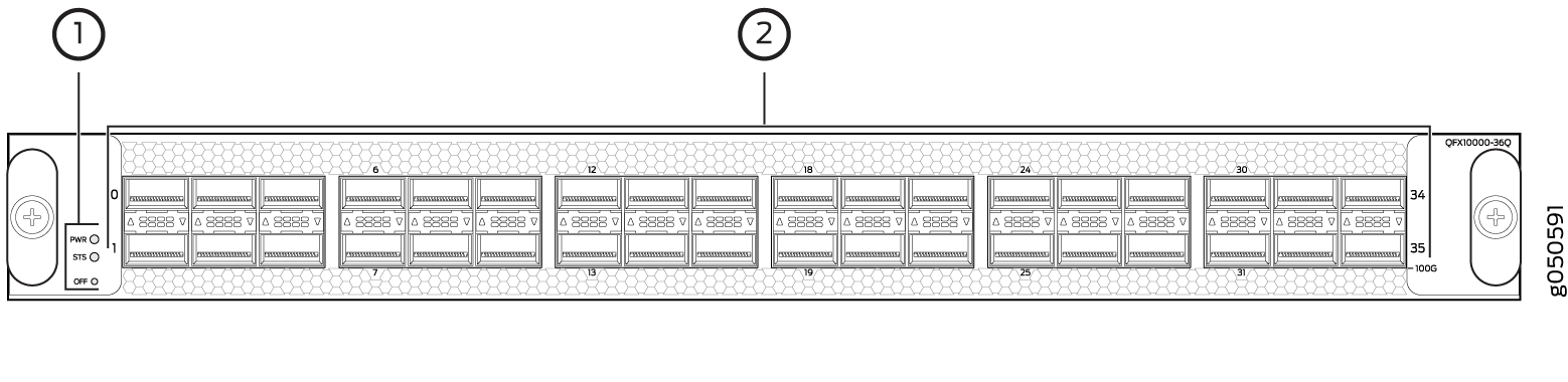
1 — Status and activity LEDs | 2 — Network ports |
Each QSFP28 socket can be configured to support:
100-Gigabit Ethernet using QSFP28 optical transceivers. When a QSFP28 transceiver is inserted into the ports marked with a fine black line underneath the socket and the port is configured for 100-Gigabit Ethernet, the two adjacent ports are disabled and the QSFP28 socket is enabled for 100-Gigabit Ethernet.
40-Gigabit Ethernet using QSFP+ optical transceivers.
10-Gigabit Ethernet using breakout cabling and attached optical transceivers. When configured for channelization, the system converts the 40-Gigabit Ethernet port into 4 independent 10-Gigabit Ethernet ports.
Any of the 36 ports 0 through 35 can be configured as either uplink or access ports.
Switch Ports
Each of the 12 QSFP28 ports supports:
100-Gigabit Ethernet QSFP28 transceivers
40-Gigabit Ethernet QSFP+ transceivers
QSFP28 direct attach copper (DAC) cables
QSFP+ DAC cables
QSFP+ to SFP+ direct attach copper breakout (DACBO) cables
Each of the 36 QSFP+ ports supports:
40-Gigabit Ethernet QSFP+ transceivers
QSFP+ DAC cables
QSFP+ to SFP+ fiber breakout and DACBO cables
Access ports
You can use 40-Gigabit Ethernet QSFP+ transceivers and QSFP+ DAC cablesin any downstream port. See QFX10000 Optical Transceiver and Cable Support.
Uplink ports
You can configure all the QSFP+ ports as uplinks.
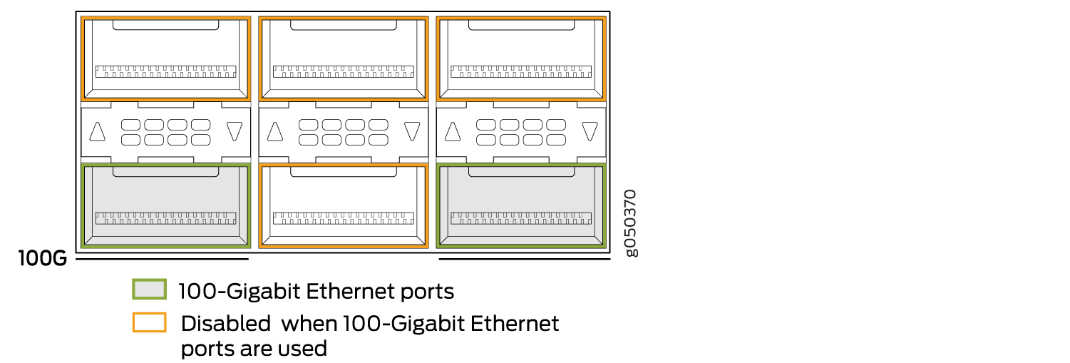
Every second and sixth port in a 6XQSFP cage on a QFX10000-36Q supports 100-Gigabit Ethernet using QSFP28 transceivers. These 100-Gigabit Ethernet ports work either as 100-Gigabit Ethernet or as 40-Gigabit Ethernet, but are recognized as 40-Gigabit Ethernet by default. See Figure 8 for a closeup view of a 6XQSFP+ cage. When a 40-Gigabit Ethernet transceiver is inserted into a 100-Gigabit Ethernet port, the port recognizes the 40-Gigabit Ethernet port speed. When a 100-Gigabit Ethernet transceiver is inserted into the port and enabled in the CLI, the port recognizes the 100-Gigabit Ethernet speed and disables two adjacent 40-Gigabit Ethernet ports. See Figure 9 and Figure 10. You can also use an 100-Gigabit Ethernet transceiver and run it at 40-Gigabit Ethernet by using the CLI to set the port speed to 40-Gigabit Ethernet.
Figure 8 shows the location of QSFP+ ports for the QFX10000-36Q.
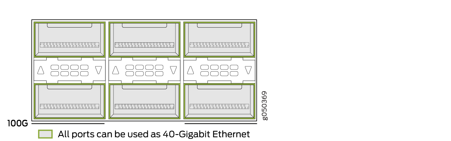
The 40-Gigabit Ethernet ports can operate independently or bundled with the next two
consecutive ports and channelized into twelve 10-Gigabit Ethernet ports as a port
range. You cannot channelize an individual port on this card. Each port is part of a
port group of 3. Only the first and fourth port in each 6XQSFP cage are available to
channelize a port range (see Figure 11). The port range must
be configured using the set chassis fpc pic port channel-speed
command. For example, to channelize the first switch port, use the set
chassis fpc 0 pic 0port
1channel-speed 10g command.
Table 9 shows the available combinations for the ports. Most 100-Gigabit Ethernet transceiver ports are used as uplinks.On the QFX10000-36Q, the ports are enabled by default, and the default configuration adds the ports to the default VLAN.
Port Number |
4X10-Gigabit Ethernet |
4X10-Gigabit Channelized Port Group |
40-Gigabit Ethernet |
100-Gigabit Ethernet |
100-Gigabit Ethernet Disables |
|---|---|---|---|---|---|
0 |
✓ |
✓ |
✓ |
– |
– |
1 |
✓ |
✓ |
✓ |
0, 2 |
|
2 |
✓ |
✓ |
– |
– |
|
3 |
✓ |
✓ |
✓ |
– |
– |
4 |
✓ |
✓ |
– |
– |
|
5 |
✓ |
✓ |
✓ |
3, 4 |
|
6 |
✓ |
✓ |
✓ |
– |
– |
7 |
✓ |
✓ |
✓ |
6, 8 |
|
8 |
✓ |
✓ |
– |
– |
|
9 |
✓ |
✓ |
✓ |
– |
– |
10 |
✓ |
✓ |
– |
– |
|
11 |
✓ |
✓ |
✓ |
9, 10 |
|
12 |
✓ |
✓ |
✓ |
– |
– |
13 |
✓ |
✓ |
✓ |
12, 14 |
|
14 |
✓ |
✓ |
– |
– |
|
15 |
✓ |
✓ |
✓ |
– |
– |
16 |
✓ |
✓ |
– |
– |
|
17 |
✓ |
✓ |
✓ |
15, 16 |
|
18 |
✓ |
✓ |
✓ |
– |
– |
19 |
✓ |
✓ |
✓ |
18, 20 |
|
20 |
✓ |
✓ |
– |
– |
|
21 |
✓ |
✓ |
✓ |
– |
– |
22 |
✓ |
✓ |
– |
– |
|
23 |
✓ |
✓ |
✓ |
21, 22 |
|
24 |
✓ |
✓ |
✓ |
– |
– |
25 |
✓ |
✓ |
✓ |
24, 26 |
|
26 |
✓ |
✓ |
– |
– |
|
27 |
✓ |
✓ |
✓ |
– |
– |
28 |
✓ |
✓ |
– |
– |
|
29 |
✓ |
✓ |
✓ |
27, 28 |
|
30 |
✓ |
✓ |
✓ |
– |
– |
31 |
✓ |
✓ |
✓ |
30, 32 |
|
32 |
✓ |
✓ |
– |
– |
|
33 |
✓ |
✓ |
✓ |
– |
– |
34 |
✓ |
✓ |
– |
– |
|
35 |
✓ |
✓ |
✓ |
33, 34 |
Status and Activity LEDs
All ports have an up or down indicator for each port and four bi-colored LEDs that show port status and link activity based on whether or not the port is configured for channelization. See Figure 12 and Table 10.
Color |
State |
Description |
|---|---|---|
Unlit |
Off |
The port is administratively disabled, there is no power, the link is down, or a transceiver is not present. All sub-channels are disabled. |
Green |
On steadily |
A link is established. When channelized, all sub-channels are up. When not channelized, it indicates no activity. |
Blinking |
A link is up and there is activity. When not channelized, it indicates the port is up and active in either 40-Gigabit or 100-Gigabit mode. When channelized, all four channels are up and active. |
|
Yellow or Amber (channelized) |
On steadily |
At least one channel link is up, but not all channels are up. There is no activity on the channel link. |
Flashing |
At least one channel link is up, but not all channels are up. There is activity on the channel link. |
|
Slow blink, or blip |
The beacon function is enabled on one or more sub-channels. |
|
Blinking |
One or more sub-channels has a fault condition. |
|
Yellow or Amber (non-channelized) |
Blinking |
A single LED blinking indicates and interface fault. All four LEDs blink to indicate the beacon function was enabled on the port. |
See Also
QFX10000-60S-6Q Line Card
The QFX10000-60S-6Q line card consists of 60 small form-factor pluggable plus (SFP+) ports,that support 10-Gbps or 1-Gbps port speeds, 2 dual-speed QSFP28 ports that support either 40-Gbps or 100-Gbps port speed, and 4 QSFP+ ports that support 40-Gbps. All of the SFP+ ports are configured to 10-Gbps by default. The QSFP28 ports are configured to 40-Gbps by default, but port 60 and port 64 are dual-speed ports and can be configured to support either 40-Gigabit Ethernet or 100-Gigabit Ethernet optical transceivers. See the Hardware Compatibility Tool for details of supported optical transceivers.
The QFX10000-60S-6Q line card is supported on Junos OS Release 17.1R1 and later.
Junos OS Release 17.1R1 does not support 1-Gigabit Ethernet on the 10-Gigabit Ethernet SFP+ ports. Junos OS Release 17.2R1 supports 1-Gigabit Ethernet on the 10-Gigabit Ethernet SFP+ ports.
This topic describes:
- Hardware Features
- Port Groups
- Channelization of 40-Gigabit Ethernet Ports
- Using Copper and Fiber SFP Transceivers
- SFP+ Status and Activity LEDs
- QSFP+ and QSFP28 Status and Activity LEDs
Hardware Features
The line cards in QFX10000 modular switches combine a Packet Forwarding Engine and Ethernet interfaces in a single assembly. Line cards are field-replaceable units (FRUs) that can be installed in the line card slots on the front of the switch chassis. The line cards are hot-insertable and hot-removable; you can remove and replace them without powering off the switch or disrupting switch functions. See Figure 13.
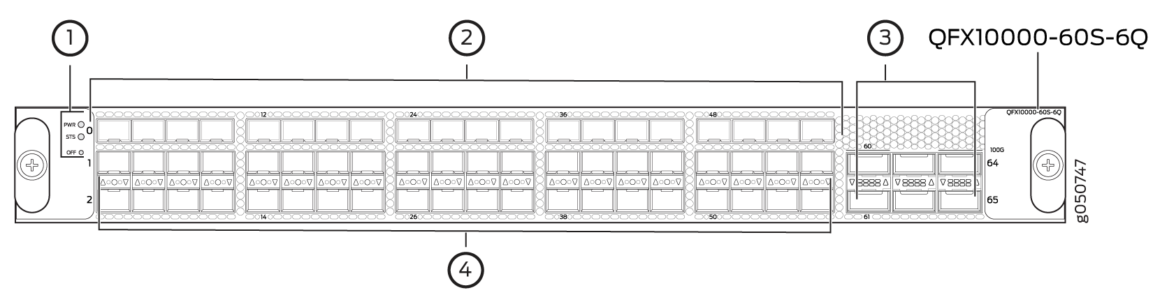
1 — Power LED, status LED, and offline button | 3 — QSFP28 ports, QSFP+ ports, and port groups |
2 — SFP+ ports |
Each QSFP28 port (60 and 64) controls a port group and can be configured to support:
100-Gigabit Ethernet using QSFP28 optical transceivers. The interface speeds are configured by port group. When a QSFP28 transceiver is inserted into the one of the QSFP28 ports marked with a fine black line above the port (60 or 64) and the port is configured for 100-Gigabit Ethernet, the two adjacent ports are disabled and the QSFP28 port is enabled for 100-Gigabit Ethernet. When port 60 is configured for 100-Gbps, ports 61 and 62 are disabled; when port 64 is configured for 100-Gbps, ports 63 and 65 are disabled.
40-Gigabit Ethernet using QSFP+ optical transceivers. The default speed is 40 Gbps.
10-Gigabit Ethernet using breakout cabling and attached optical transceivers. When configured for channelization, the system converts the 40-Gigabit Ethernet port into 4 independent 10-Gigabit Ethernet ports. Use the
set chassis fpc slot-number port port-number channel-speed speedcommand to change the port speed.
Each QSFP+ port (61, 62, 63, and 65 is part of a port group and is controlled either by the associated QSFP28 port (60 or 64). A QSFP28 port operating at 40-Gpbs speeds, the QSFP+ ports can be configured to support:
40-Gigabit Ethernet using QSFP+ optical transceivers. The default speed is 40 Gbps.
10-Gigabit Ethernet using breakout cables with attached optical transceivers. When configured for channelization, the system converts the 40-Gigabit Ethernet port into 4 independent 10-Gigabit Ethernet ports. Use the
set chassis fpc slot-number port port-number channel-speed speedcommand to change the port speed.
Each SFP+ port (0 through 59) can be configured to support:
10-Gigabit Ethernet using SFP+ optical transceivers. The default speed is 10 Gbps.
1-Gigabit Ethernet using SFP optical or SFP-T copper transceivers. See Using Copper and Fiber SFP Transceivers.
Any of the 66 ports 0 through 65 can be configured as either uplink or access ports. The ports are enabled by default, and the default configuration adds the ports to the default VLAN.
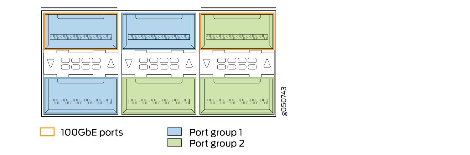
Port Groups
The six combination ports of QSFP28 and QSFP+ can operate either as six independent 40-Gigabit Ethernet ports or as two port groups. The first port group is controlled by QSFP28 port 60 and administratively bundled with QSFP+ ports 61 and 62. The second port group is controlled by QSFP28 port 64 and administratively bundled with QSFP+ ports 63 and 65. To enable the port group, insert a 100-Gigabit Ethernet transceiver into the QSFP28 port and configure a port for 100-Gbps. Junos OS enables the QSFP28 port at 100-Gbps speed and disables the two QSFP+ ports bundled in the port group. Figure 14 shows the location of QSFP28 ports and port groups for the QFX10000-60S-6Q. Table 11 shows the available combinations for the ports.
Port Number |
4X10-Gigabit Ethernet |
4X10-Gigabit Channelized Port Group |
40-Gigabit Ethernet |
100-Gigabit Ethernet |
100-Gigabit Ethernet Disables |
|---|---|---|---|---|---|
60 |
✓ |
✓ |
✓ |
✓ |
61, 62 |
61 |
✓ |
✓ |
– |
– |
|
62 |
✓ |
✓ |
– |
– |
|
63 |
✓ |
✓ |
✓ |
– |
– |
64 |
✓ |
✓ |
✓ |
63, 65 |
|
65 |
✓ |
✓ |
– |
– |
Channelization of 40-Gigabit Ethernet Ports
Channelization from a 40-Gigabit Ethernet port into 4 independent 10-Gigabit Ethernet ports is supported on the QSFP28 and QSFP+ ports. Channelization to 50-Gbps or 25-Gbps speed is not supported on the 100-Gigabit Ethernet QSFP28 port. All ports in the port group are channelized when port 60 or port 64 are channelized. Ports cannot be channelized individually.
To channelize a 40-Gbps port to 4 independent 10-Gbps ports,
use the set chassis fpc slot-number pic pic-number port port-number channel-speed speed command. For example, to channelize ports 60 through 62 for a line card in
slot 6:
[edit chassis fpc 6 pic 1]
user@switch# set port 60 channel-speed 10g
Review your configuration and issue the commit command.
If you want to return the port to the default, delete the speed statement from the configuration at the [chassis
fpc 6 pic 1 port port-number] hierarchy
level and commit the configuration. The network port is reset to the
default 40-Gigabit Ethernet interface.
[edit chassis fpc 6 pic 1]
user@switch# delete port 60 channel-speed 10g
Using Copper and Fiber SFP Transceivers
When you configure the 10-Gigabit Ethernet ports 0 to 59 as 1-Gigabit Ethernet ports, you can use optical fiber SFP transceivers in any of the ports. However, copper SFP transceivers are restricted to the lower two rows. See Figure 15.
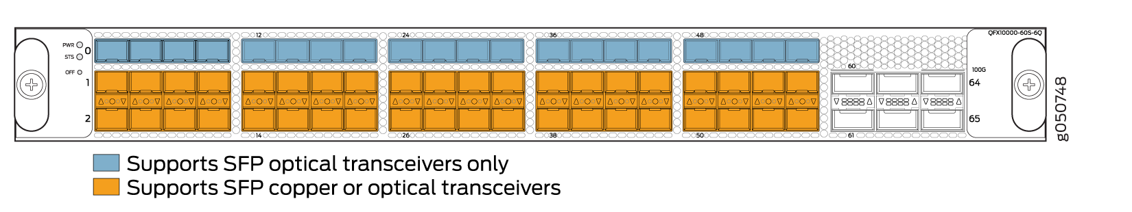
When you use the latest OEM part number FCLF8521P2BTL (printed on the transceiver label), you can install 1GbE transceivers (such as QFX-SFP-1GE-T) in any port with no restrictions. The same applies for devices that support 10GbE copper transceivers. However, if you are using the older OEM part number SP7041-M1-JN (not shipped in last 3+ years) instead, do not install 1GbE copper transceivers (such as QFX-SFP-1GE-T) directly above or below another 1GbE copper transceiver. Use only the top row or bottom row to avoid damage to the device caused when the transceivers are installed above or below each other.
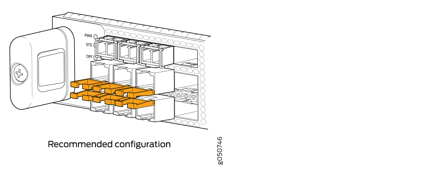
Because 1 Gbps copper SFP transceivers are physically larger than optical SFP transceivers, there is insufficient room for 3 copper SFP transceivers to be stacked. Use the top row only for optical SFP transceivers. You can stack copper transceivers in the bottom two rows. Ports are arranged belly-to-belly. Stacking three SFP transceivers in a column can damage the line card. For the recommended configuration, see Figure 16.
SFP+ Status and Activity LEDs
All status and activity LEDs for the SFP+ ports are located between the second and third rows of SFP+. The up arrow, circle, and down arrow indicate the row of the status. A bi-color LED indicates the status and activity. See Figure 17 and Table 12.
An up arrow indicates the first row.
A circle indicates the second row.
A down arrow indicates the third row.
Color |
State |
Description |
|---|---|---|
Unlit |
Off |
The port is administratively disabled, there is no power, the link is down, or a transceiver is not present. |
Green |
On steadily |
A link is established. |
Yellow or Amber |
Slow blink, or blip |
The beacon function is enabled on one or more sub-channels. |
Blinking |
The interface has a fault condition. |
QSFP+ and QSFP28 Status and Activity LEDs
All QSFP+ and QSFP28 ports have an up or down indicator for each port and four bi-colored LEDs that show port status and link activity based on whether or not the port is configured for channelization. See Table 13.
Color |
State |
Description |
|---|---|---|
Unlit |
Off |
The port is administratively disabled, there is no power, the link is down, or a transceiver is not present. All sub-channels are disabled. |
Green |
On steadily |
A link is established. When channelized, all sub-channels are up. When not channelized, it indicates no activity. |
Yellow or Amber |
On steadily |
At least one channel link is up, but not all channels are up. |
Slow blink, or blip |
The beacon function is enabled on one or more sub-channels. |
|
Blinking |
One or more sub-channels has a fault condition. |
See Also
QFX10K-12C-DWDM Coherent Line Card
The QFX10K-12C-DWDM line card is the combination of Juniper Networks Junos OS for QFX10000 modular chassis software running on Juniper Networks JNP10K-LC1104 hardware. The QFX10000-12C-DWDM line card provides up to 1.2 Tbps packet forwarding for cloud providers, service providers, and enterprises that need coherent dense wavelength-division multiplexing (DWDM) with MACsec security features. The 6 port line card, with built-in optics, supports flexible rate modulation at 100 Gbps, 150 Gbps, and 200 Gbps speeds.
The QFX10K-12C-DWDM line card is supported on Junos OS Release 17.2R1 and later.
This topic includes:
- Hardware Features
- Compatibility
- Optical Transmit Specifications
- Optical Receive Specifications
- Status and Activity LEDs
Hardware Features
The line cards in QFX10000 modular switches combine a Packet Forwarding Engine and Ethernet interfaces in a single assembly. Line cards are field-replaceable units (FRUs) that can be installed in the line card slots on the front of the switch chassis. The line cards are hot-insertable and hot-removable; you can remove and replace them without powering off the switch or disrupting switch functions. See Figure 19.
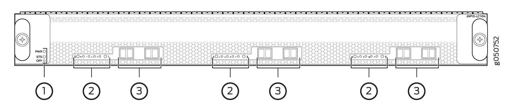
1 — Power and status LEDs | 3 — Ports with embedded optics |
2 — Network link and Ethernet link LEDs |
Each QFX10K-12C-DWDM has 6 physical interfaces (OT) that connect to one of three built-in flexible rate optical transponders. Each transponder connects four 100-Gigabit Ethernet logical interfaces (ET) to one of three forwarding ASICs. The ASICs through a MACsec to PHY to MACsec encryption is optionally supported on each 100-Gigabit Ethernet interface. See Figure 20.
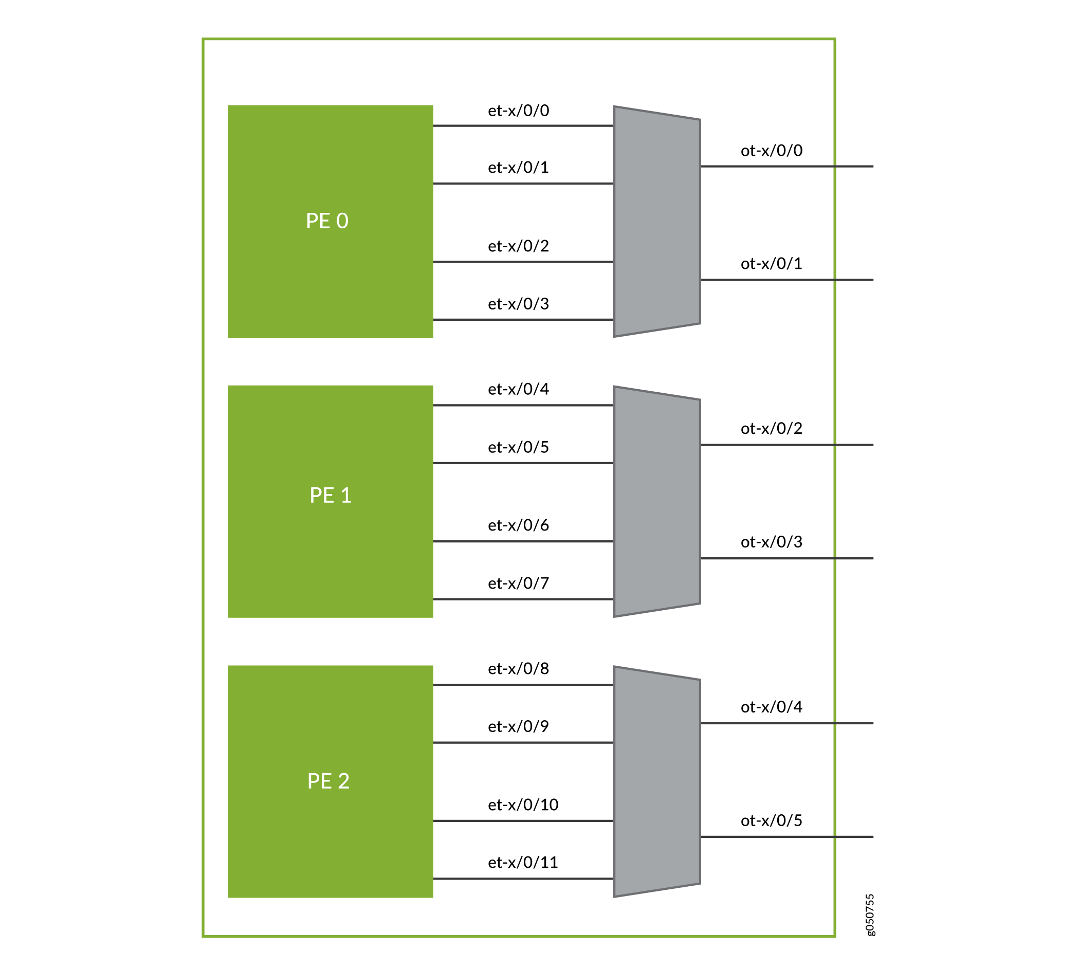
All optical properties are configured under the OT interface. Use the set interfaces ot-x/x/x optics-options CLI command to set these options.
Each of the six network ports can operate in one of three modulation formats, see Table 14.
Speed |
Modulation |
Distance |
|---|---|---|
100 Gbps |
DP-PSK |
long haul–2485.49 miles (4000 km) |
150 Gbps |
DP-8QAM |
regional or metro–1242.74 miles (2000 km) |
200 Gbps |
DP-16QAM |
metro DCI–621.37 miles (1000 km) |
Compatibility
The Juniper Networks Open Cloud Interconnect solution includes integrated 100 GbE coherent optics on Juniper Networks QFX Series switches; MX Series 5G Universal Routing Platforms and PTX Series Packet Transport Routers; and BTI Packet Optical Platforms optimized for DCI. As part of the Open Cloud Interconnect solution, the QFX10K-12C-DWDM coherent line card is compatible with many third-party optical products as well as Juniper Networks optical solutions and offerings. The QFX10K-12C-DWDM coherent line card is interoperable with the BTI Series Packet Optical Transport UFM6 in 100 Gbps, 150 Gbps, and 200 Gbps modes. It is also compatible with the MX Series MICs and PTX Series PICs in 100 Gbps mode using SDFEC or SDFEC25 FEC. See Table 15.
Platform |
Cards |
Model Information |
|---|---|---|
MX Series |
MIC3-100G-DWDM |
See the Hardware Compatibility Tool, MIC3-100G-DWDM. |
PTX Series |
PTX-5-100-WDM P1-PTX-2-100G-WDM |
See the Hardware Compatibility Tool, PTX-5-100-WDM. See the Hardware Compatibility Tool, P1-PTX-2-100G-WDM. |
Optical Transmit Specifications
The line card is connected using single-mode fiber (SMF) and LC connectors. See Table 16 and Table 17 for the optical transponder specifications.
Specification |
Value |
|---|---|
Standards compliance |
IEEE 802.3 IEC 60825-1 Class 1 |
Modulation format |
DP-QPSK, DP-8QAM, DP-16QAM |
Line rate |
DP-QPSK = 136.66 Gbps DP-8QAM = 205 Gbps DP-16QAM= 273.33 Gbps |
FEC types |
SDFEC and SDFEC25 (default) |
Channel-plan wavelength range |
Extended C-band, 1528.77 nm to 1568.36 nm |
Channel-plan frequency range |
196.1 THz to 191.35 THz |
Channel spacing |
0.125 THz |
Channel tunability |
128 channels. See 1.2-Terabyte Per Second DWDM OTN Module Wavelengths. |
Optical transmitter output power (on) |
-12 to 1.5 dBm, 0.1 dB steps, +/- 1 dB accuracy |
Optical transmitter output power (off) |
≤ -40 dBM |
Optical transmitter wavelength accuracy |
+/- 1.8 GHz |
Optical transmitter channel tuning time |
≤ 90 seconds across C-band |
TX output power OSNR |
≥ 36 dB |
Optical Receive Specifications
Specification |
100G DP-PSK |
150G DP-8QAM |
200G DP-16QAM |
|---|---|---|---|
Optical receiver input power range (low Rx OSNR) |
-18 dBm to 0 dBm |
-18 dBm to 0 dBm |
-18 dBm to 0 dBm |
Optical receiver input power range (unamplified /dark fiber applications) |
-32 dBm to 0 dBm |
-27 dBm to 0 dBm |
-25 dBm to 0 dBm |
Optical receiver damage input power threshold |
+17 dBm |
+17 dBm |
+17 dBm |
Optical receiver minimum OSNR (back-to-back), typical |
10.5 dB |
15.0 dB |
17 dB |
Optical receiver minimum OSNR (back-to-back), worst-case, EOL |
11.5 dB |
16.0 dB |
19.0 dB |
Optical receiver chromatic dispersion tolerance |
+/- 70,000 ps/nm |
+/- 45,000 ps/nm |
+/- 30,000 ps/nm |
Optical receiver PMD tolerance |
30 ps mean DGD |
20 ps mean DGD |
15 ps mean DGD |
Optical receiver polarization tracking |
100 krad/s |
50 krad/s |
50 krad/s |
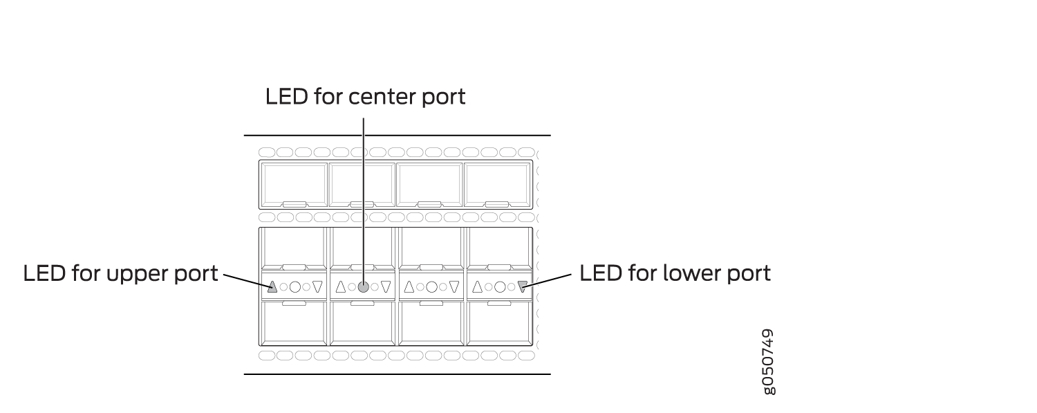
Status and Activity LEDs
There are two kinds of LEDs for the network ports: port LEDs and Ethernet link LEDs. The LEDs for the six physical ports indicate the link state of an OT interface. There are four LEDs in between each port pair that indicate the link state of the associated ET interfaces, see Figure 21. To determine the link state of the OT interface, see Table 18.
1 — Port LEDs (OT interfaces) | 2 — Ethenet LEDs (ET interfaces) |
Color |
Description |
|---|---|
Unlit |
The port is not configured. |
Solid Green |
A link is established on the OT interface. |
Solid Amber |
The optical module associated with the port has a fault condition, or the port is configured but the link is down. |
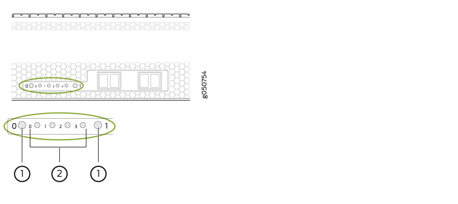
You can also determine the configuration of the ET interfaces by examining the pattern of the 4 Ethernet LEDs. See Table 19. To determine the link status and of those ET interfaces see Table 20.
Modulation Format |
Aggregate Data Rate |
OT Interface Data Rate |
ET Interface |
Configuration |
|
|---|---|---|---|---|---|
Ports 0, 2, |
1, 3, 5 |
||||
16-QAM (x2) |
4 x 100 Gigabit Ethernet |
200 Gbps |
200 Gbps |
0, 1, 2, 3 |
2 independent 200 Gbps 16-QAM |
QPSK and 16-QAM |
3 x 100 Gigabit Ethernet |
100 Gbps |
200 Gbps |
0, 2, 3 |
Independent QPSK and 16-QAM |
16-QAM and QPSK |
3 x 100 Gigabit Ethernet |
200 Gbps |
100 Gbps |
0, 1, 2 |
Independent QPSK and 16-QAM |
8-QAM |
3 x 100 Gigabit Ethernet |
150 Gbps |
150 Gbps |
0, 1, 2 |
2 Coupled 150 Gbps 8-QAM |
QPSK and QPSK |
2 x 100 Gigabit Ethernet |
100 Gbps |
100 Gbps |
0,2 |
Independent 100G QPSK |
Color |
Description |
|---|---|
Unlit |
The ET interface is down. |
Solid Green |
The ET interface is up but there is no activity. |
Blinking Green |
The link is up on the ET interface and there is activity. |
1.2-Terabyte Per Second DWDM OTN Module Wavelengths
The PTX10K-LC1104 coherent line card and the QFX10000-12C-DWDM line card provide six 200-Gbps coherent MACsec ports with built-in long-reach optics. DWDM channel frequency offsets are 0.02 THz. The QFX10000-12C-DWDM line card is available for the QFX10008 and QFX10016 switch chassis running Junos OS Release 17.3R1 and later. The PTX10K-LC1104 coherent line card is available for the PTX10008 and PTX10016 routers. See Table 21 for the available channel frequencies and wavelengths.
Frequency (THz) |
Wavelength (nm) |
Offset (GHz) |
|---|---|---|
191.35 |
1566.72 |
12.5/50 |
191.36 |
1566.62 |
12.5 |
191.38 |
1566.52 |
12.5 |
191.39 |
1566.42 |
12.5 |
191.4 |
1566.31 |
12.5/50/100 |
191.41 |
1566.21 |
12.5 |
191.43 |
1566.11 |
12.5 |
191.44 |
1566.01 |
12.5 |
191.45 |
1565.91 |
12.5/50 |
191.46 |
1565.8 |
12.5 |
191.48 |
1565.7 |
12.5 |
191.49 |
1565.6 |
12.5 |
191.5 |
1565.5 |
12.5/50/100 |
191.51 |
1565.39 |
12.5 |
191.53 |
1565.29 |
12.5 |
191.54 |
1565.19 |
12.5 |
191.55 |
1565.09 |
12.5/50 |
191.56 |
1564.99 |
12.5 |
191.58 |
1564.88 |
12.5 |
191.59 |
1564.78 |
12.5 |
191.6 |
1564.68 |
12.5/50/100 |
191.61 |
1564.58 |
12.5 |
191.63 |
1564.48 |
12.5 |
191.64 |
1564.37 |
12.5 |
191.65 |
1564.27 |
12.5/50 |
191.66 |
1564.17 |
12.5 |
191.68 |
1564.07 |
12.5 |
191.69 |
1563.97 |
12.5 |
191.7 |
1563.86 |
12.5/50/100 |
191.71 |
1563.76 |
12.5 |
191.73 |
1563.66 |
12.5 |
191.74 |
1563.56 |
12.5 |
191.75 |
1563.46 |
12.5/50 |
191.76 |
1563.35 |
12.5 |
191.78 |
1563.25 |
12.5 |
191.79 |
1563.15 |
12.5 |
191.8 |
1563.05 |
12.5/50/100 |
191.81 |
1562.95 |
12.5 |
191.83 |
1562.84 |
12.5 |
191.84 |
1562.74 |
12.5 |
191.85 |
1562.64 |
12.5/50 |
191.86 |
1562.54 |
12.5 |
191.88 |
1562.44 |
12.5 |
191.89 |
1562.33 |
12.5 |
191.9 |
1562.23 |
12.5/50/100 |
191.91 |
1562.13 |
12.5 |
191.93 |
1562.03 |
12.5 |
191.94 |
1561.93 |
12.5 |
191.95 |
1561.83 |
12.5/50 |
191.96 |
1561.72 |
12.5 |
191.98 |
1561.62 |
12.5 |
191.99 |
1561.52 |
12.5 |
192 |
1561.42 |
12.5/50/100 |
192.01 |
1561.32 |
12.5 |
192.03 |
1561.22 |
12.5 |
192.04 |
1561.11 |
12.5 |
192.05 |
1561.01 |
12.5/50 |
192.06 |
1560.91 |
12.5 |
192.08 |
1560.81 |
12.5 |
192.09 |
1560.71 |
12.5 |
192.1 |
1560.61 |
12.5/50/100 |
192.11 |
1560.51 |
12.5 |
192.13 |
1560.4 |
12.5 |
192.14 |
1560.3 |
12.5 |
192.15 |
1560.2 |
12.5/50 |
192.16 |
1560.1 |
12.5 |
192.18 |
1560 |
12.5 |
192.188 |
1559.9 |
12.5 |
192.2 |
1559.79 |
12.5/50/100 |
192.21 |
1559.69 |
12.5 |
192.23 |
1559.59 |
12.5 |
192.24 |
1559.49 |
12.5 |
192.25 |
1559.39 |
12.5/50 |
192.26 |
1559.29 |
12.5 |
192.28 |
1559.19 |
12.5 |
192.29 |
1559.08 |
12.5 |
192.3 |
1558.98 |
12.5/50/100 |
192.31 |
1558.88 |
12.5 |
192.33 |
1558.78 |
12.5 |
192.34 |
1558.68 |
12.5 |
192.35 |
1558.58 |
12.5/50 |
192.36 |
1558.48 |
12.5 |
192.38 |
1558.38 |
12.5 |
192.39 |
1558.27 |
12.5 |
192.4 |
1558.17 |
12.5/50/100 |
192.41 |
1558.07 |
12.5 |
192.43 |
1557.97 |
12.5 |
192.44 |
1557.87 |
12.5 |
192.45 |
1557.77 |
12.5/50 |
192.46 |
1557.67 |
12.5 |
192.48 |
1557.57 |
12.5 |
192.49 |
1557.47 |
12.5 |
192.5 |
1557.36 |
12.5/50/100 |
192.51 |
1557.26 |
12.5 |
192.53 |
1557.16 |
12.5 |
192.54 |
1557.06 |
12.5 |
192.55 |
1556.96 |
12.5/50 |
192.56 |
1556.86 |
12.5 |
192.58 |
1556.76 |
12.5 |
192.59 |
1556.66 |
12.5 |
192.6 |
1556.56 |
12.5/50/100 |
192.61 |
1556.45 |
12.5 |
192.63 |
1556.35 |
12.5 |
192.64 |
1556.25 |
12.5 |
192.65 |
1556.15 |
12.5/50 |
192.66 |
1556.05 |
12.5 |
192.68 |
1555.95 |
12.5 |
192.69 |
1555.85 |
12.5 |
192.7 |
1555.75 |
12.5/50/100 |
192.71 |
1555.65 |
12.5 |
192.73 |
1555.55 |
12.5 |
192.74 |
1555.44 |
12.5 |
192.75 |
1555.34 |
12.5/50 |
192.76 |
1555.24 |
12.5 |
192.78 |
1555.14 |
12.5 |
192.79 |
1555.04 |
12.5 |
192.8 |
1554.94 |
12.5/50/100 |
192.81 |
1554.84 |
12.5 |
192.83 |
1554.74 |
12.5 |
192.84 |
1554.64 |
12.5 |
192.85 |
1554.54 |
12.5/50 |
192.86 |
1554.44 |
12.5 |
192.88 |
1554.34 |
12.5 |
192.89 |
1554.24 |
12.5 |
192.9 |
1554.13 |
1554.134 |
192.91 |
1554.03 |
12.5 |
192.93 |
1553.93 |
12.5 |
192.94 |
1553.83 |
12.5 |
192.95 |
1553.73 |
12.5/50 |
192.96 |
1553.63 |
12.5 |
192.98 |
1553.53 |
12.5 |
192.99 |
1553.43 |
12.5 |
193 |
1553.33 |
12.5/50/100 |
193.01 |
1553.23 |
12.5 |
193.03 |
1553.13 |
12.5 |
193.04 |
1553.03 |
12.5 |
193.05 |
1552.93 |
12.5/50 |
193.06 |
1552.83 |
12.5 |
193.08 |
1552.73 |
12.5 |
193.09 |
1552.63 |
12.5 |
193.1 |
1552.52 |
12.5/50/100 |
193.11 |
1552.42 |
12.5 |
193.13 |
1552.32 |
12.5 |
193.14 |
1552.22 |
12.5 |
193.15 |
1552.12 |
12.5/50 |
193.16 |
1552.02 |
12.5 |
193.18 |
1551.92 |
12.5 |
193.19 |
1551.82 |
12.5 |
193.2 |
1551.72 |
12.5/50/100 |
193.21 |
1551.62 |
12.5 |
193.23 |
1551.52 |
12.5 |
193.24 |
1551.42 |
12.5 |
193.25 |
1551.32 |
12.5/50 |
193.26 |
1551.22 |
12.5 |
193.28 |
1551.12 |
12.5 |
193.29 |
1551.02 |
12.5 |
193.3 |
1550.92 |
12.5/50/100 |
193.31 |
1550.82 |
12.5 |
193.33 |
1550.72 |
12.5 |
193.34 |
1550.62 |
12.5 |
193.35 |
1550.52 |
12.5/50 |
193.36 |
1550.42 |
12.5 |
193.38 |
1550.32 |
12.5 |
193.39 |
1550.22 |
12.5 |
193.4 |
1550.12 |
12.5/50/100 |
193.41 |
1550.02 |
12.5 |
193.43 |
1549.92 |
12.5 |
193.44 |
1549.82 |
12.5 |
193.45 |
1549.72 |
12.5/50 |
193.46 |
1549.62 |
12.5 |
193.48 |
1549.52 |
12.5 |
193.49 |
1549.42 |
12.5 |
193.5 |
1549.32 |
12.5/50/100 |
193.51 |
1549.22 |
12.5 |
193.53 |
1549.12 |
12.5 |
193.54 |
1549.02 |
12.5 |
193.55 |
1548.92 |
12.5/50 |
193.56 |
1548.82 |
12.5 |
193.58 |
1548.72 |
12.5 |
193.59 |
1548.62 |
12.5 |
193.6 |
1548.52 |
12.5/50/100 |
193.61 |
1548.42 |
12.5 |
193.63 |
1548.32 |
12.5 |
193.64 |
1548.22 |
12.5 |
193.65 |
1548.12 |
12.5/50 |
193.66 |
1548.02 |
12.5 |
193.68 |
1547.92 |
12.5 |
193.69 |
1547.82 |
12.5 |
193.7 |
1547.72 |
12.5/50/100 |
193.71 |
1547.62 |
12.5 |
193.73 |
1547.52 |
12.5 |
193.74 |
1547.42 |
12.5 |
193.75 |
1547.32 |
12.5/50 |
193.76 |
1547.22 |
12.5 |
193.78 |
1547.12 |
12.5 |
193.79 |
1547.02 |
12.5 |
193.8 |
1546.92 |
12.5/50/100 |
193.81 |
1546.82 |
12.5 |
193.83 |
1546.72 |
12.5 |
193.84 |
1546.62 |
12.5 |
193.85 |
1546.52 |
12.5/50 |
193.86 |
1546.42 |
12.5 |
193.88 |
1546.32 |
12.5 |
193.89 |
1546.22 |
12.5 |
193.9 |
1546.12 |
12.5/50/100 |
193.91 |
1546.02 |
12.5 |
193.93 |
1545.92 |
12.5 |
193.94 |
1545.82 |
12.5 |
193.95 |
1545.72 |
12.5/50 |
193.96 |
1545.62 |
12.5 |
193.98 |
1545.52 |
12.5 |
193.99 |
1545.42 |
12.5 |
194 |
1545.32 |
12.5/50/100 |
194.01 |
1545.22 |
12.5 |
194.03 |
1545.12 |
12.5 |
194.04 |
1545.02 |
12.5 |
194.05 |
1544.92 |
12.5/50 |
194.06 |
1544.82 |
12.5 |
194.08 |
1544.73 |
12.5 |
194.09 |
1544.63 |
12.5 |
194.1 |
1544.53 |
12.5/50/100 |
194.11 |
1544.43 |
12.5 |
194.13 |
1544.33 |
12.5 |
194.14 |
1544.23 |
12.5 |
194.15 |
1544.13 |
12.5/50 |
194.16 |
1544.03 |
12.5 |
194.18 |
1543.93 |
12.5 |
194.19 |
1543.83 |
12.5 |
194.2 |
1543.73 |
12.5/50/100 |
194.21 |
1543.63 |
12.5 |
194.23 |
1543.53 |
12.5 |
194.24 |
1543.43 |
12.5 |
194.25 |
1543.33 |
12.5/50 |
194.26 |
1543.23 |
12.5 |
194.28 |
1543.14 |
12.5 |
194.29 |
1543.04 |
12.5 |
194.3 |
1542.94 |
12.5/50/100 |
194.31 |
1542.84 |
12.5 |
194.33 |
1542.74 |
12.5 |
194.34 |
1542.64 |
12.5 |
194.35 |
1542.54 |
12.5/50 |
194.36 |
1542.44 |
12.5 |
194.38 |
1542.34 |
12.5 |
194.39 |
1542.24 |
12.5 |
194.4 |
1542.14 |
12.5/50/100 |
194.41 |
1542.04 |
12.5 |
194.43 |
1541.94 |
12.5 |
194.44 |
1541.85 |
12.5 |
194.45 |
1541.75 |
12.5/50 |
194.46 |
1541.65 |
12.5 |
194.48 |
1541.55 |
12.5 |
194.49 |
1541.45 |
12.5 |
194.5 |
1541.35 |
12.5/50/100 |
194.51 |
1541.25 |
12.5 |
194.53 |
1541.15 |
12.5 |
194.54 |
1541.05 |
12.5 |
194.55 |
1540.95 |
12.5/50 |
194.56 |
1540.85 |
12.5 |
194.58 |
1540.76 |
12.5 |
194.59 |
1540.66 |
12.5 |
194.6 |
1540.56 |
12.5/50/100 |
194.61 |
1540.46 |
12.5 |
194.63 |
1540.36 |
12.5 |
194.64 |
1540.26 |
12.5 |
194.65 |
1540.16 |
12.5/50 |
194.66 |
1540.06 |
12.5 |
194.68 |
1539.96 |
12.5 |
194.69 |
1539.87 |
12.5 |
194.7 |
1539.77 |
12.5/50/100 |
194.71 |
1539.67 |
12.5 |
194.73 |
1539.57 |
12.5 |
194.74 |
1539.47 |
12.5 |
194.75 |
1539.37 |
12.5/50 |
194.76 |
1539.27 |
12.5 |
194.78 |
1539.17 |
12.5 |
194.79 |
1539.07 |
12.5 |
194.8 |
1538.98 |
12.5/50/100 |
194.81 |
1538.88 |
12.5 |
194.83 |
1538.78 |
12.5 |
194.84 |
1538.68 |
12.5 |
194.85 |
1538.58 |
12.5/50 |
194.86 |
1538.48 |
12.5 |
194.88 |
1538.38 |
12.5 |
194.89 |
1538.29 |
12.5 |
194.9 |
1538.19 |
12.5/50/100 |
194.91 |
1538.09 |
12.5 |
194.93 |
1537.99 |
12.5 |
194.94 |
1537.89 |
12.5 |
194.95 |
1537.79 |
12.5/50 |
194.96 |
1537.69 |
12.5 |
194.98 |
1537.59 |
12.5 |
194.99 |
1537.5 |
12.5 |
195 |
1537.4 |
12.5/50/100 |
195.01 |
1537.3 |
12.5 |
195.03 |
1537.2 |
12.5 |
195.04 |
1537.1 |
12.5 |
195.05 |
1537 |
12.5/50 |
195.06 |
1536.9 |
12.5 |
195.08 |
1536.8 |
12.5 |
195.09 |
1536.7 |
12.5 |
195.1 |
1536.6 |
12.5/50/100 |
195.11 |
1536.51 |
12.5 |
195.13 |
1536.41 |
12.5 |
195.14 |
1536.31 |
12.5 |
195.15 |
1536.22 |
12.5/50 |
195.16 |
1536.12 |
12.5 |
195.18 |
1536.02 |
12.5 |
195.19 |
1535.92 |
12.5 |
195.2 |
1535.82 |
12.5/50/100 |
195.21 |
1535.72 |
12.5 |
195.23 |
1535.63 |
12.5 |
195.24 |
1535.53 |
12.5 |
195.25 |
1535.43 |
12.5/50 |
195.26 |
1535.33 |
12.5 |
195.28 |
1535.23 |
12.5 |
195.29 |
1535.13 |
12.5 |
195.3 |
1535.03 |
12.5/50/100 |
195.31 |
1534.94 |
12.5 |
195.33 |
1534.84 |
12.5 |
195.34 |
1534.74 |
12.5 |
195.35 |
1564.64 |
12.5/50 |
195.36 |
1534.55 |
12.5 |
195.38 |
1534.45 |
12.5 |
195.39 |
1534.35 |
12.5 |
195.4 |
1534.25 |
12.5/50/100 |
195.41 |
1534.15 |
12.5 |
195.43 |
1534.05 |
12.5 |
195.44 |
1533.96 |
12.5 |
195.45 |
1533.86 |
12.5/50 |
195.46 |
1533.76 |
12.5 |
195.48 |
1533.66 |
12.5 |
195.49 |
1533.56 |
12.5 |
195.5 |
1533.47 |
12.5/50/100 |
195.51 |
1533.37 |
12.5 |
195.53 |
1533.27 |
12.5 |
195.54 |
1533.17 |
12.5 |
195.55 |
1533.07 |
12.5/50 |
195.56 |
1532.98 |
12.5 |
195.58 |
1532.88 |
12.5 |
195.59 |
1532.78 |
12.5 |
195.6 |
1532.68 |
12.5/50/100 |
195.61 |
1532.58 |
12.5 |
195.63 |
1532.49 |
12.5 |
195.64 |
1532.39 |
12.5 |
195.65 |
1532.29 |
12.5/50 |
195.66 |
1532.19 |
12.5 |
195.68 |
1532.09 |
12.5 |
195.69 |
1532 |
12.5 |
195.7 |
1531.9 |
12.5/50/100 |
195.71 |
1531.8 |
12.5 |
195.73 |
1531.7 |
12.5 |
195.74 |
1531.61 |
12.5 |
185.75 |
1531.51 |
12.5/50 |
185.76 |
1531.41 |
12.5 |
195.78 |
1531.31 |
12.5 |
195.79 |
1531.21 |
12.5 |
195.8 |
1531.12 |
12.5/50/100 |
195.81 |
1531.02 |
12.5 |
195.83 |
1530.92 |
12.5 |
195.84 |
1530.82 |
12.5 |
195.85 |
1530.73 |
12.5/50 |
195.86 |
1530.63 |
12.5 |
195.88 |
1530.53 |
12.5 |
195.89 |
1530.43 |
12.5 |
195.9 |
1530.33 |
12.5/50/100 |
195.91 |
1530.34 |
12.5 |
195.93 |
1530.24 |
12.5 |
195.94 |
1530.04 |
12.5 |
195.95 |
1529.94 |
12.5/50 |
195.96 |
1529.85 |
12.5 |
195.98 |
1529.75 |
12.5 |
195.99 |
1529.65 |
12.5 |
196 |
1529.55 |
12.5/50/100 |
196.01 |
1529.46 |
12.5 |
196.03 |
1529.36 |
12.5 |
196.04 |
1529.26 |
12.5 |
196.05 |
1529.16 |
12.5/50 |
196.06 |
1529.07 |
12.5 |
196.08 |
1528.97 |
12.5 |
196.09 |
1528.87 |
12.5 |
196.1 |
1528.77 |
12.5/50/100 |
QFX10000 Line Card LEDs
All QFX10000 line cards have three bi-colored LEDs (see Figure 22).
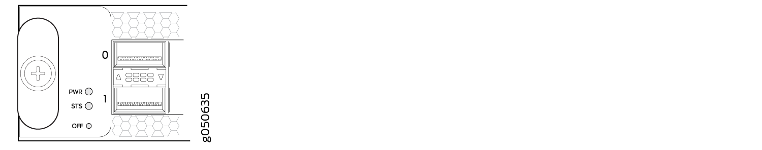
Table 22 describes the functions of the line card LEDs.
Label |
Color |
State |
Description |
|---|---|---|---|
PWR |
Green |
On steadily |
The line card is receiving power. |
Yellow |
Blinking |
The line card has a power error, such as insufficient power. |
|
Unlit |
Off |
The line card is not receiving power. |
|
STS |
Green |
On steadily |
The line card is online and functioning normally. |
Green |
Blinking |
The beacon feature is enabled on the line card. |
|
Yellow |
On steadily |
The line card is booting. |
|
Yellow |
Blinking |
The line card is detecting an error. |
|
Unlit |
Off |
The line card is offline. |
|
OFF |
Green |
On steadily |
The line card is offline. |
Offline Button
The offline/online button is recessed below the faceplate directly below the status (STS) LED. You can take any QFX10000 offline or online by using either of these two methods:
Press the OFF button with a non-conductive pin tool, such as a toothpick, until the STS LED goes out (about 5 seconds).
Issue the CLI command:
user@host> request chassis pic fpc-slot fpc-slot pic-slot pic-slot offline