Returning the QFX10000 Chassis or Component
How to Return a Hardware Component to Juniper Networks, Inc.
If a hardware component fails, you need to contact Juniper Networks, Inc. to obtain a Return Material Authorization (RMA) number. This number is used to track the returned material at the factory and to return repaired or new components to the customer as needed.
Do not return any component to Juniper Networks, Inc. unless you have first obtained an RMA number. Juniper Networks, Inc. reserves the right to refuse shipments that do not have an RMA. Refused shipments are returned to the customer by collect freight.
For more information about return and repair policies, see the customer support webpage at https://support.juniper.net/support/.
For product problems or technical support issues, contact the Juniper Networks Technical Assistance Center (JTAC) by using the Service Request Manager link at https://support.juniper.net/support/ or at 1-888-314-JTAC (within the United States) or 1-408-745-9500 (from outside the United States).
To return a defective hardware component:
Locating the Serial Number on a QFX10000 Switch or Component
If you are returning a switch or component to Juniper Networks for repair or replacement, you must locate the serial number of the switch or component. You must provide the serial number to the Juniper Networks Technical Assistance Center (JTAC) when you contact them to obtain a Return Materials Authorization (RMA). See Contact Customer Support to Obtain Return Material Authorization.
If the switch is operational and you can access the command-line interface (CLI), you can list serial numbers for the switch and for some components with a CLI command. If you do not have access to the CLI or if the serial number for the component does not appear in the command output, you can locate the serial number ID label on the switch or component.
If you want to find the serial number ID label on a component, you need to remove the component from the switch chassis, for which you must have the required parts and tools available.
- Listing the Chassis and Component Details Using the CLI
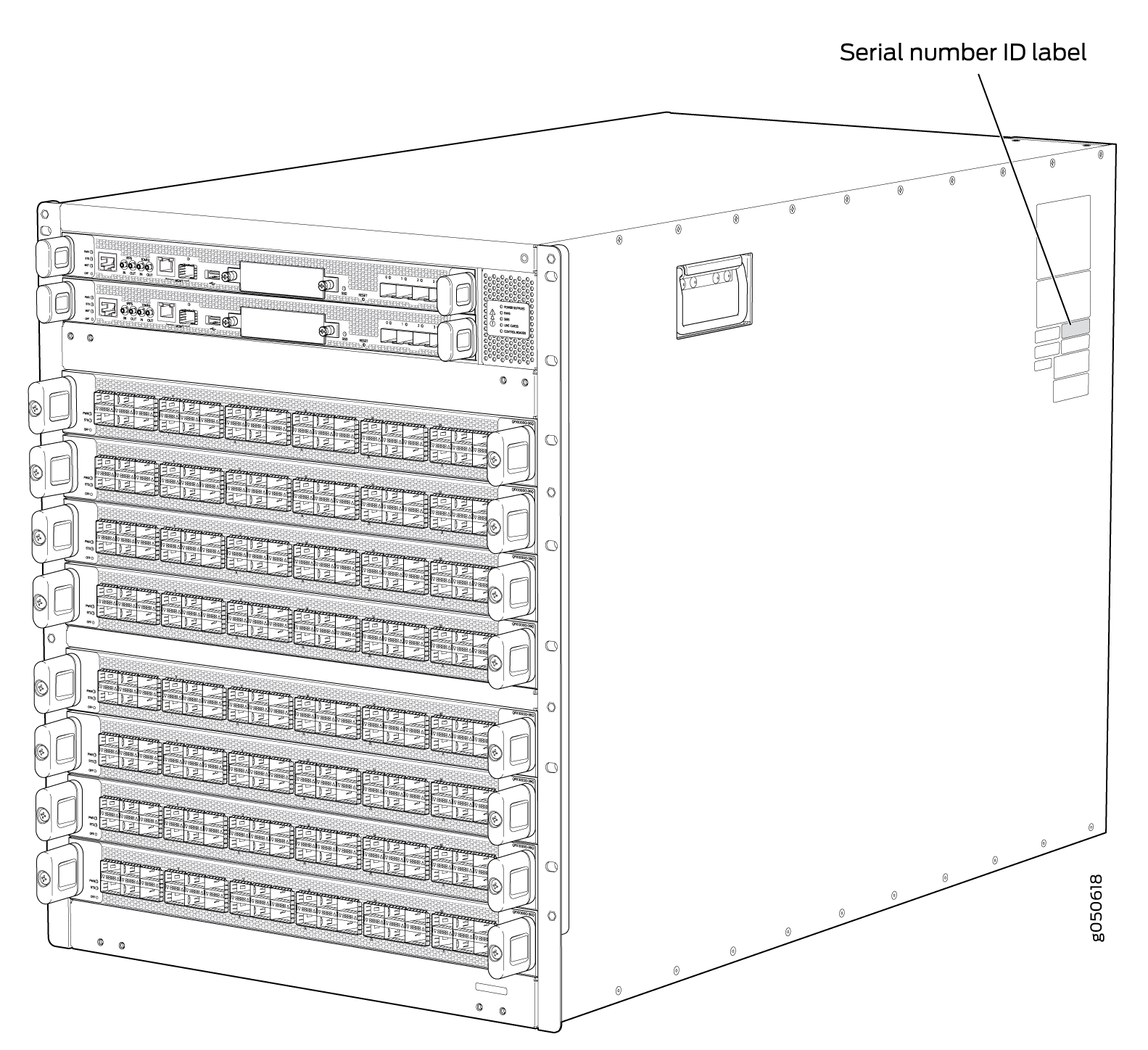
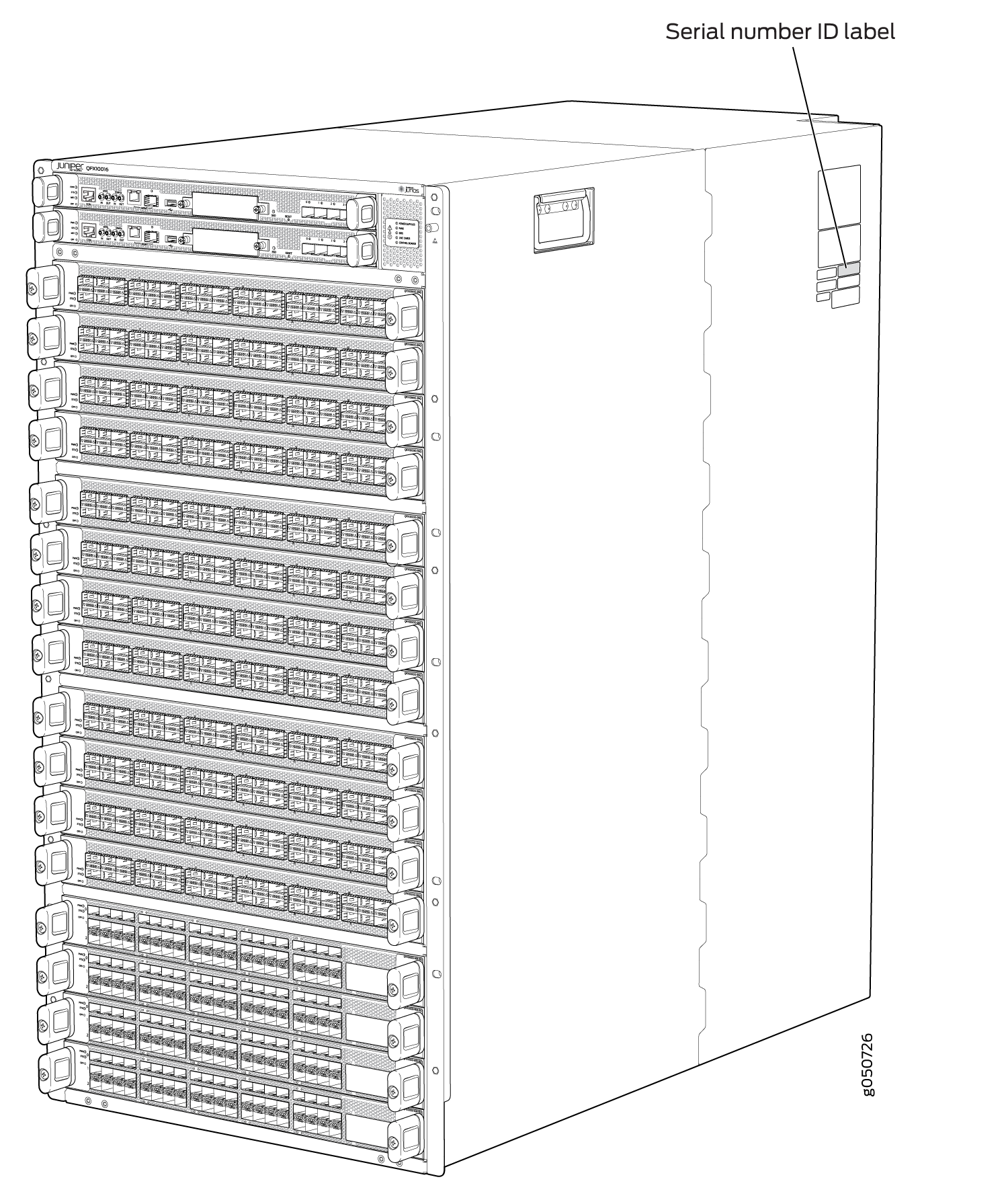
- Locating the Chassis Serial Number ID Label on a QFX10008 or QFX10016
- Locating the Serial Number ID Labels on QFX10000 Power Supplies
- Locating the Serial Number ID Labels on QFX10000 Fan Trays and Fan Tray Controllers
- Locating the Serial Number ID Labels on QFX10000 Routing Control Boards
- Locating the Serial Number ID Labels on a QFX10000 Line Card
- Locating the Serial Number ID Labels on a QFX10000 Switch Interface Board (SIB)
- Locating the Serial Number ID Label on a QFX10000 SATA SSD
Listing the Chassis and Component Details Using the CLI
To list the QFX10008 or QFX10016 chassis and the components
and their serial numbers, use the show chassis hardware CLI operational mode command.
user@device> show chassis hardware
 Hardware inventory:
Item             Version  Part number  Serial number     Description
Chassis                                BLANK             QFX10008
Midplane         REV 03   750-054097   ACAM4920          QFX10008 Midplane
Routing Engine 0          BUILTIN      BUILTIN           Routing Engine
Routing Engine 1          BUILTIN      BUILTIN           Routing Engine
CB 0             REV 18   750-052688   ACAM7712          Control Board
CB 1             REV 18   750-052688   ACAM7720          Control Board
FPC 0            REV 16   750-051354   ACAM8331          ULC-36Q-12Q28
  CPU                     BUILTIN      BUILTIN           FPC CPU
  PIC 0                   BUILTIN      BUILTIN           36X40G
    Xcvr 0       REV 01   740-032986   QC260842          QSFP+40G-SR4
    Xcvr 1       REV 01   740-032986   QE147578          QSFP+40G-SR4
    Xcvr 2       REV 01   740-032986   QE119008          QSFP+40G-SR4
    Xcvr 3       REV 01   740-032986   QD503969          QSFP+40G-SR4
    Xcvr 4       REV 01   740-032986   QA470217          QSFP+40G-SR4
    Xcvr 5       REV 01   740-032986   QC320521          QSFP+40G-SR4
    Xcvr 6       REV 01   740-046565   QC470283          QSFP+40G-SR4
    Xcvr 7       REV 01   740-032986   QC320611          QSFP+40G-SR4
    Xcvr 11      REV      740-038624   APF14260038R37    QSFP+40G-CU3M
    Xcvr 12      REV      740-038624   APF14260030135    QSFP+40G-CU3M
    Xcvr 13      REV 01   740-032986   QB130489          QSFP+40G-SR4
    Xcvr 14      REV 01   740-032986   QD503964          QSFP+40G-SR4
 Xcvr 16      REV 01   740-032986   QA470031          QSFP+40G-SR4
    Xcvr 17      REV 01   740-032986   QE118996          QSFP+40G-SR4
    Xcvr 19      REV 01   740-032986   QE141901          QSFP+40G-SR4
    Xcvr 22      REV 01   740-032986   QA390341          QSFP+40G-SR4
    Xcvr 23      REV 01   740-032986   QD503968          QSFP+40G-SR4
    Xcvr 28      REV      740-038624   APF15230034PKT    QSFP+40G-CU3M
    Xcvr 29      REV 01   740-032986   QD503958          QSFP+40G-SR4
    Xcvr 31      REV 01   740-032986   QE118997          QSFP+40G-SR4
    Xcvr 33      REV 01   740-032986   QD503965          QSFP+40G-SR4
FPC 4            REV 16   750-051354   ACAM8342          ULC-36Q-12Q28
  CPU                     BUILTIN      BUILTIN           FPC CPU
  PIC 0                   BUILTIN      BUILTIN           36X40G
    Xcvr 1       REV 01   740-032986   QC320517          QSFP+40G-SR4
    Xcvr 2       REV 01   740-032986   QD475008          QSFP+40G-SR4
    Xcvr 3       REV      740-038624   APF14260038R44    QSFP+40G-CU3M
    Xcvr 4       REV 01   740-032986   QD372520          QSFP+40G-SR4
    Xcvr 6       REV 01   740-032986   QE119029          QSFP+40G-SR4
    Xcvr 13      REV 01   740-032986   QC320507          QSFP+40G-SR4
    Xcvr 14      REV 01   740-032986   QD420798          QSFP+40G-SR4
    Xcvr 22      REV 01   740-032986   QD512208          QSFP+40G-SR4
    Xcvr 23      REV 01   740-032986   QC320520          QSFP+40G-SR4
    Xcvr 27      REV 01   740-032986   QD472868          QSFP+40G-SR4
    Xcvr 30      REV 01   740-032986   QD503966          QSFP+40G-SR4
    Xcvr 34      REV 01   740-032986   QD420760          QSFP+40G-SR4
FPC 6            REV 16   750-051357   ACAM7581          ULC-30Q28
 CPU                     BUILTIN      BUILTIN           FPC CPU
  PIC 0                   BUILTIN      BUILTIN           30X100G
    Xcvr 0       REV 01   740-061405   1ACQ103602H       100GBASE-SR4
    Xcvr 1       REV 01   740-061405   1ACQ103601M       100GBASE-SR4
    Xcvr 4       REV01    740-061001   LEO1528003N       QSFP28-100G-CU3M
    Xcvr 7       REV01    740-061001   LEO15280045       QSFP28-100G-CU3M
    Xcvr 15      REV01    740-061001   LEO1528004J       QSFP28-100G-CU3M
    Xcvr 23      REV01    740-061001   LEO15280053       QSFP28-100G-CU3M
FPD Board
Power Supply 0   REV 01   740-049388   1EDL44300CY       AC 12V Power Supply
Power Supply 1   REV 01   740-049388   1EDL44300BW       AC 12V Power Supply
Power Supply 2   REV 01   740-049388   1EDL44300CC       AC 12V Power Supply
FTC 0
FTC 1            REV 08   750-050108   ACAM9108          QFX10000 FTC
Fan Tray 0       REV 03   760-054372   ACAM3620          QFX10008 FHB
Fan Tray 1       REV 03   760-054372   ACAM3613          QFX10008 FHB
SIB 0            REV 10   750-050058   ACAM8348          QFX10008 SIB
SIB 1            REV 05   750-050058   ACAM3938          QFX10008 SIB
SIB 2            REV 05   750-050058   ACAM3940          QFX10008 SIB
SIB 3            REV 05   750-050058   ACAM3967          QFX10008 SIB
SIB 4            REV 05   750-050058   ACAM3927          QFX10008 SIB
SIB 5            REV 05   750-050058   ACAM3953          QFX10008 SIB

user@device>
Locating the Chassis Serial Number ID Label on a QFX10008 or QFX10016
Locating the Serial Number ID Labels on QFX10000 Power Supplies
The power supplies installed in a QFX10000 are field-replaceable units (FRUs). For each FRU, you must remove the FRU from the switch chassis to see the FRU serial number ID label.
QFX10000-PWR-AC power supply—The serial number ID label is on the right side of the power supply. See Figure 3.
Figure 3: QFX10000 PWR-AC Power Supply Serial Number Location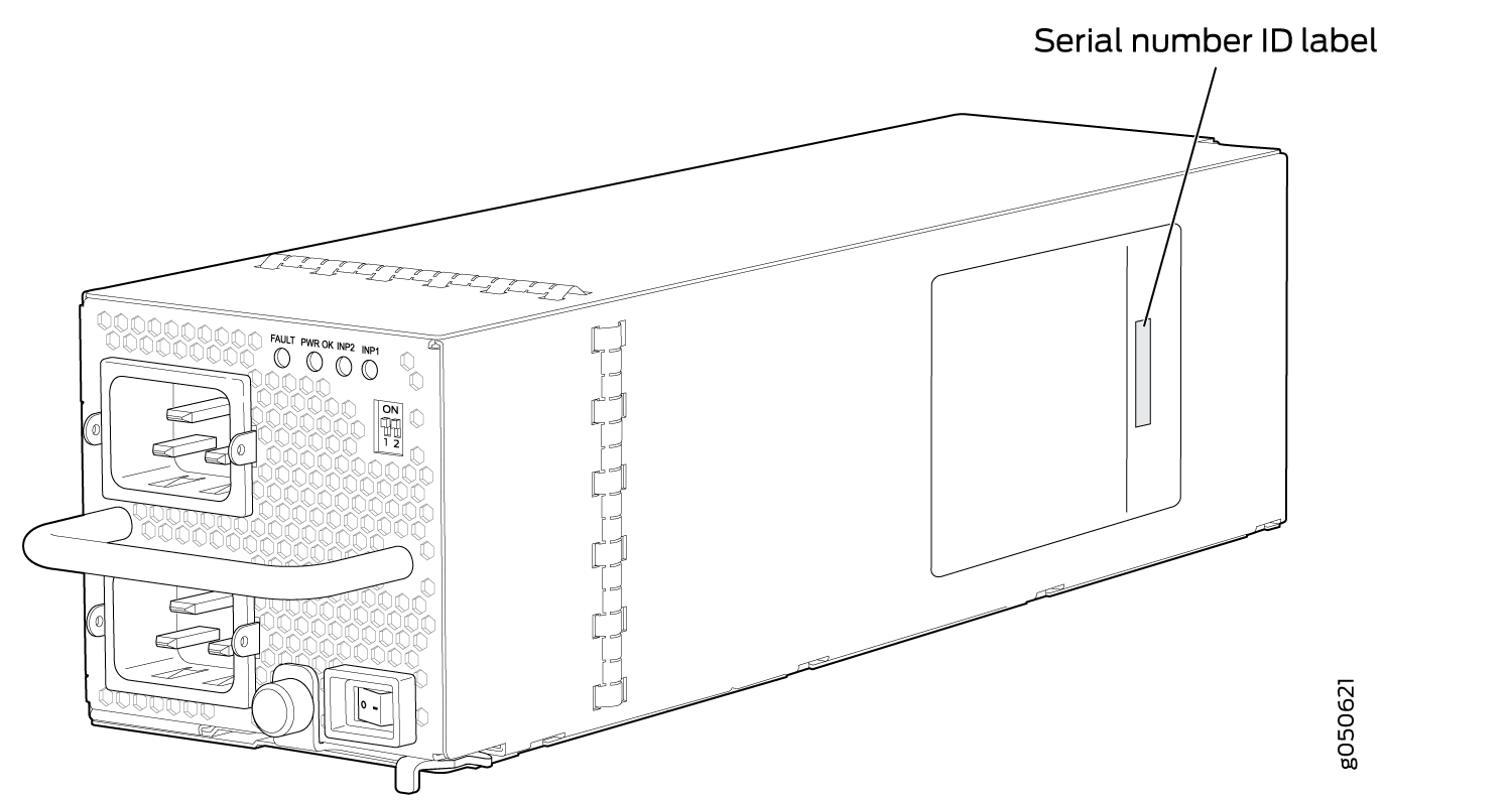
JNP10K-PWR-AC2 power supply—The serial ID label is on the right side of the power supply. See Figure 4.
Figure 4: JNP10K-PWR-AC2 Power Supply Serial Number Location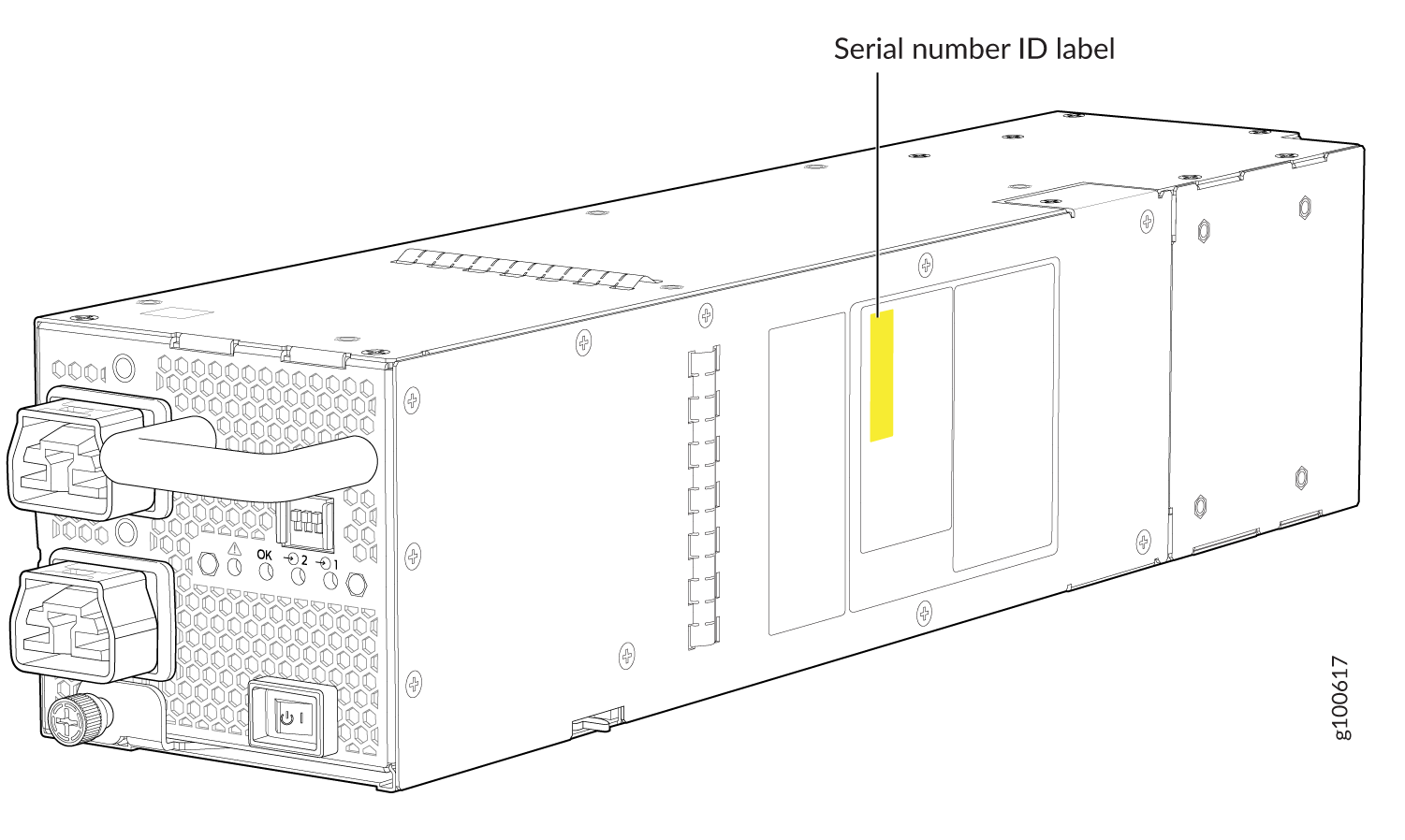
QFX10000-PWR-DC power supply—The serial number ID label is on the left side of the power supply. See Figure 5.
Figure 5: QFX10000 PWR-DC Power Supply Serial Number Location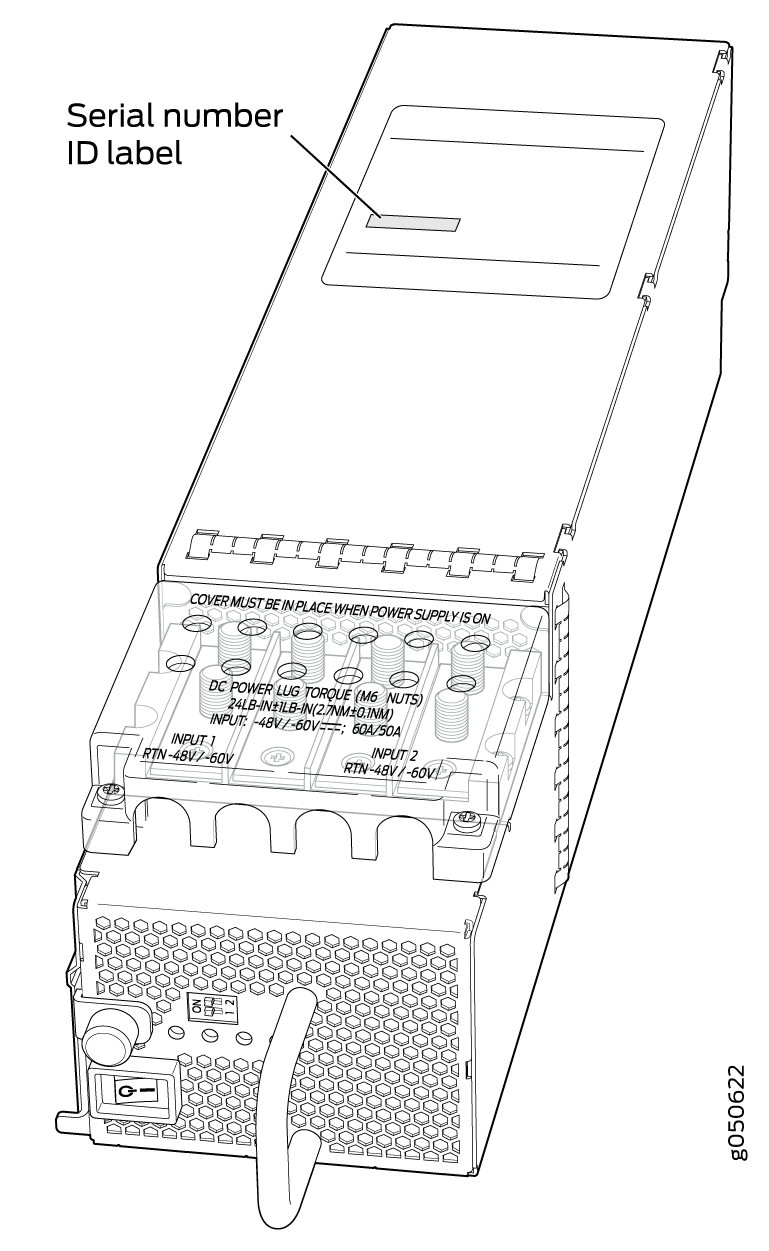
JNP10K-PWR-DC2 power supply—The serial number ID label is on the left side of the power supply. See Figure 6.
Figure 6: JNP10K-PWR-DC2 Power Supply Serial Number Location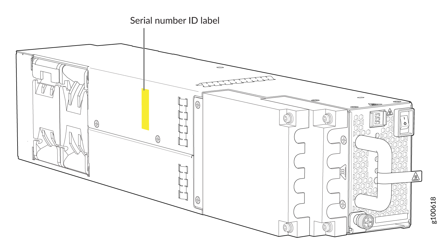
Locating the Serial Number ID Labels on QFX10000 Fan Trays and Fan Tray Controllers
The two fan trays and their associated fan tray controllers installed in a QFX10000 are field-replaceable units (FRUs). For each FRU, you must remove the FRU from the switch chassis to see the FRU serial number ID label.
Fan tray–The serial number ID label is located on the inside of the fan tray at the base of the fan tray Control Board. See Figure 7.
Figure 7: QFX10000 Fan Tray Serial Number Location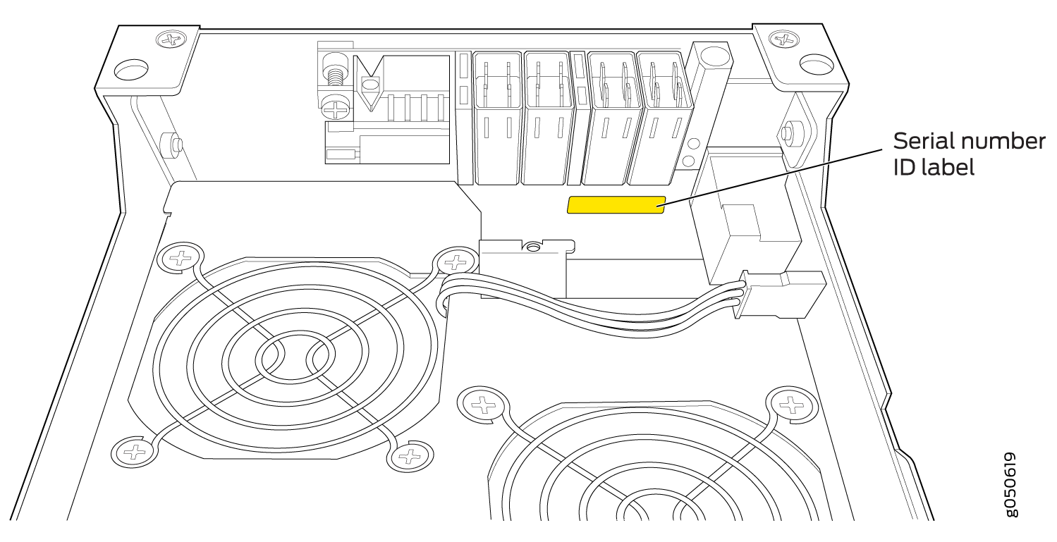
Fan tray controller–The serial number ID label is located on the top of the fan tray controller. See Figure 8.
Figure 8: QFX10000 Fan Tray Controller Serial Number Location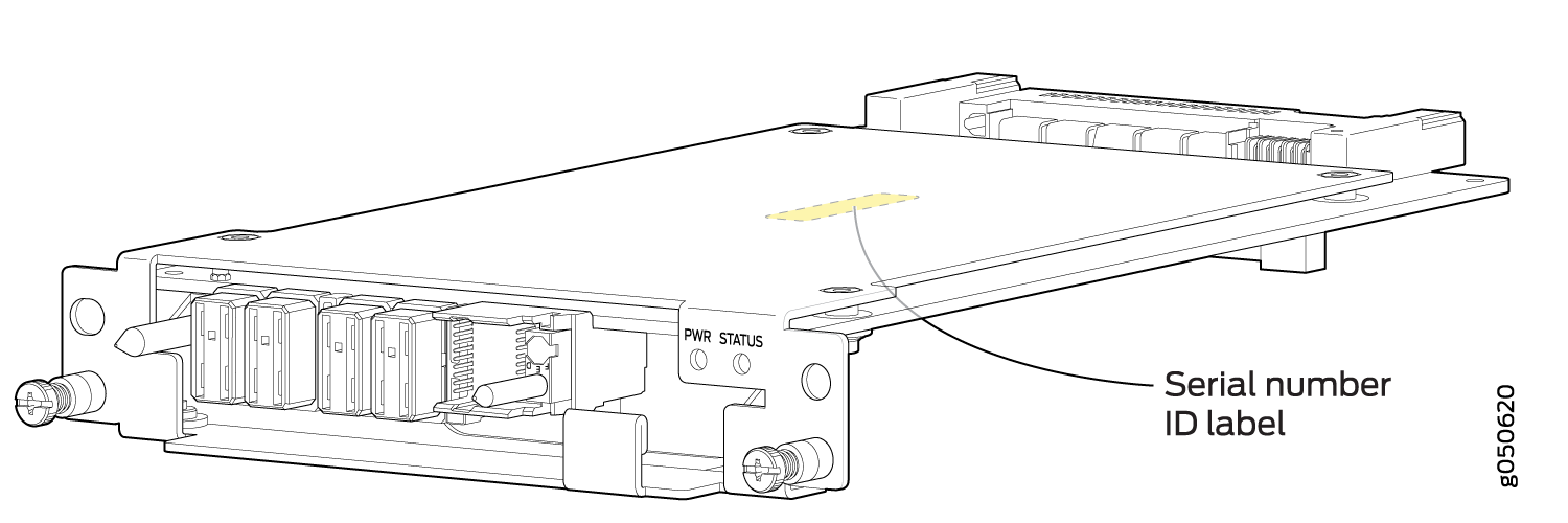
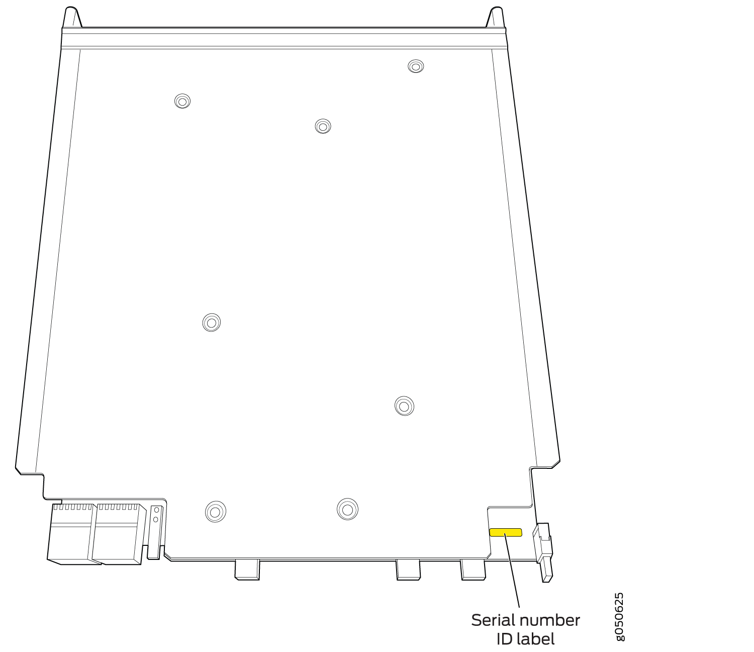
Locating the Serial Number ID Labels on QFX10000 Routing Control Boards
The serial number ID label for a Routing Control Board is located on the connector end of the unit. See Figure 9.
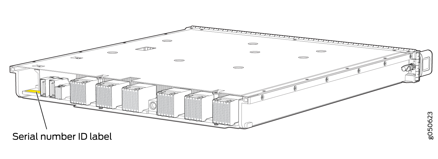
Locating the Serial Number ID Labels on a QFX10000 Line Card
The serial number ID label for a line card is located on the connector end of the card. See Figure 10.
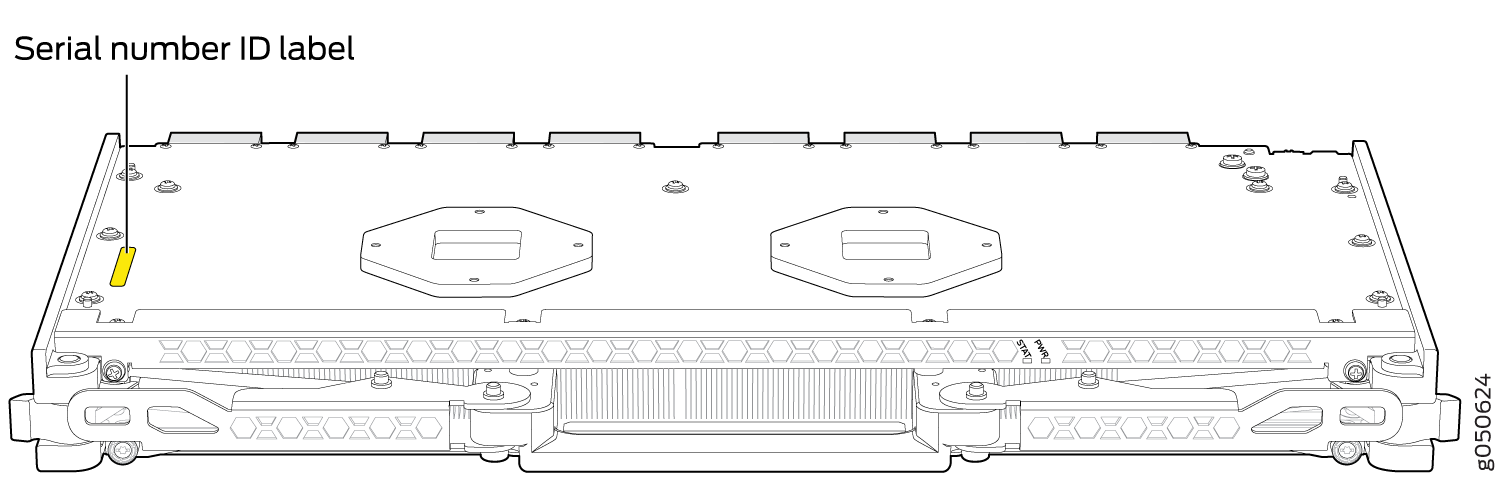
Locating the Serial Number ID Labels on a QFX10000 Switch Interface Board (SIB)
The serial number ID label for a SIB is located on the PC board. See Figure 11.
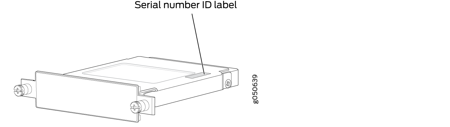
Locating the Serial Number ID Label on a QFX10000 SATA SSD
The serial number for a SATA SSD is located on top of the drive. See Figure 12.
Packing a QFX10000 or Component for Shipping
Follow this procedure if you are returning a QFX10000 chassis or component to Juniper Networks for repair or replacement.
Before you pack a QFX10000 or component:
Ensure that you have taken the necessary precautions to prevent electrostatic discharge (ESD) damage. See Prevention of Electrostatic Discharge Damage.
Pack your chassis or component using one of these materials:
Use the packing material from the replacement chassis or component
Retrieve the original shipping carton and packing materials
Contact your JTAC representative if you do not have these materials, to learn about approved packing materials. See Contact Customer Support to Obtain Return Material Authorization.
Ensure that you have the following parts and tools available:
ESD grounding strap.
Electrostatic bag, one for each component.
If you are returning the chassis:
A 13/32-in. or 10-mm open-end or socket wrench to install the bracket bolts on the chassis and shipping pallet
An appropriate screwdriver for the mounting screws used on your rack.
This topic covers:
Packing a QFX10000 Switch Chassis for Shipping
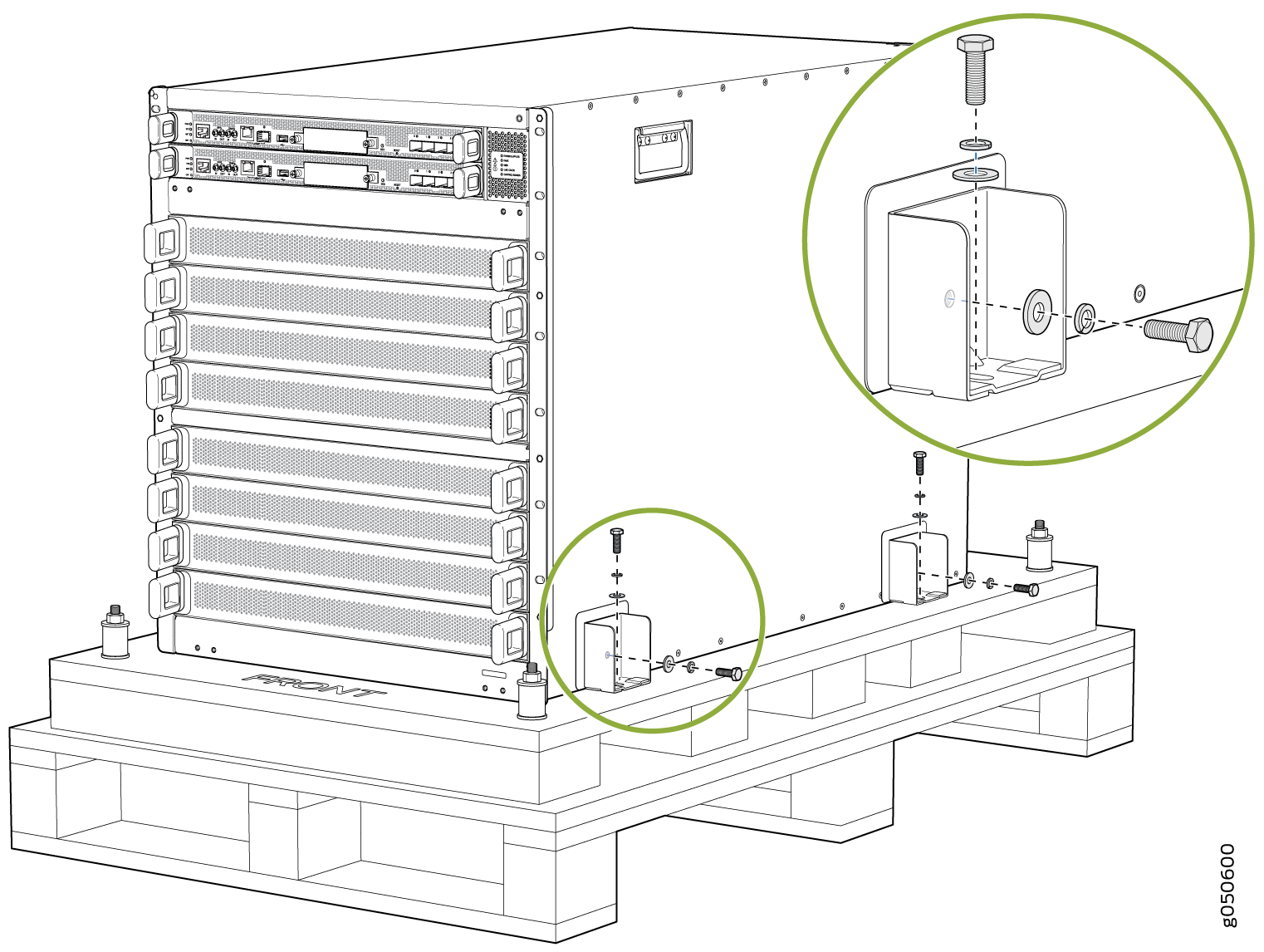
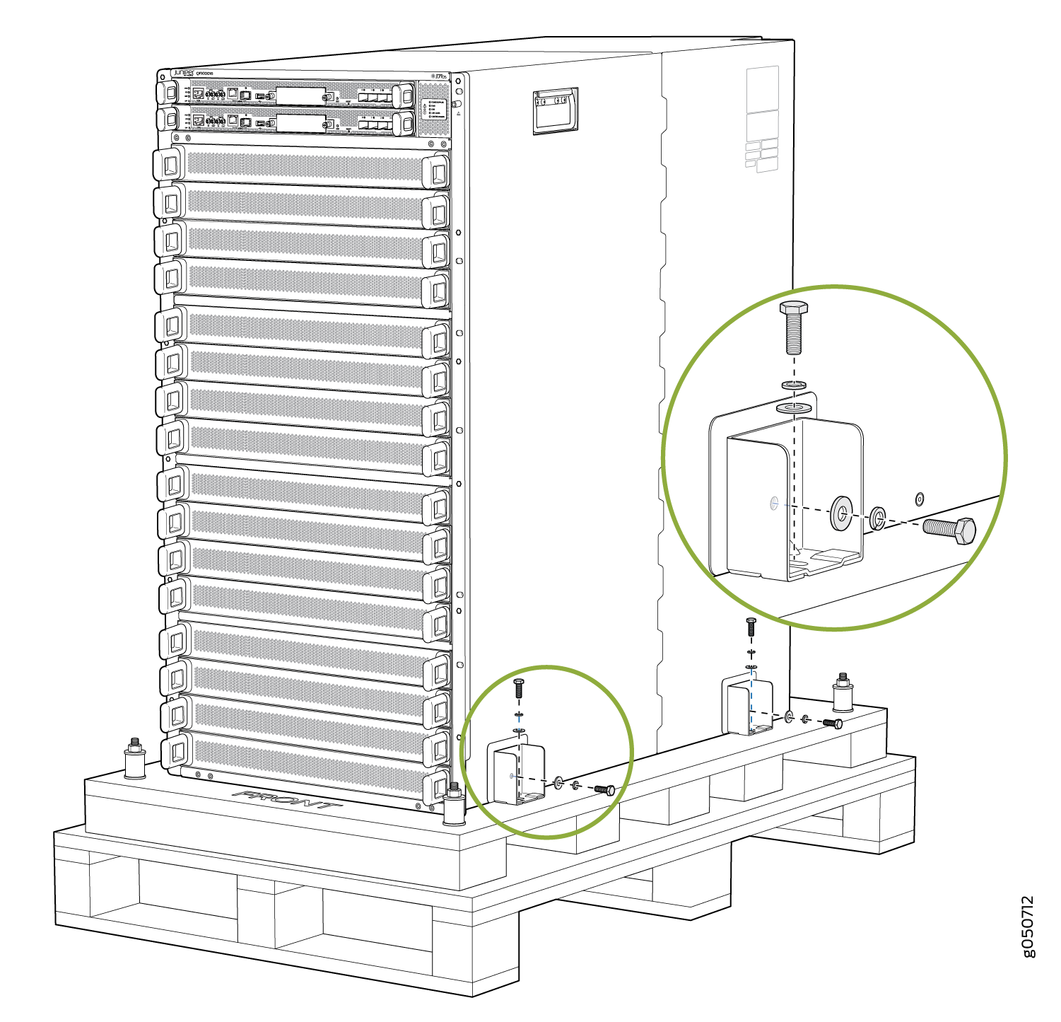
The QFX10000 is shipped in a cardboard box that has a two-layer wooden pallet base with foam cushioning between the layers. The switch chassis is bolted to the pallet base with four pallet fasteners, two on each side of the chassis. See Figure 13 for the stacking configuration of the QFX10008 and Figure 14 for the QFX10016.
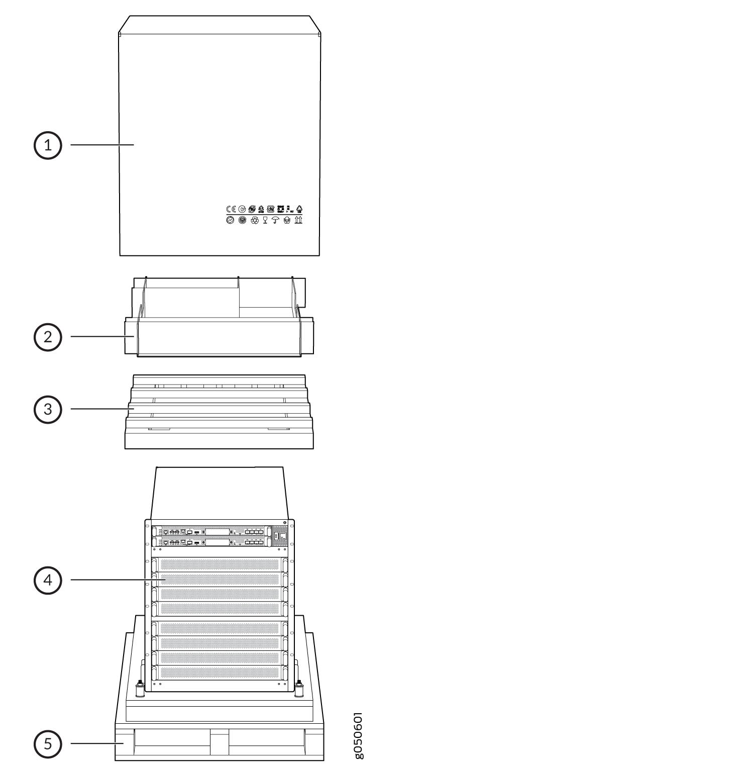
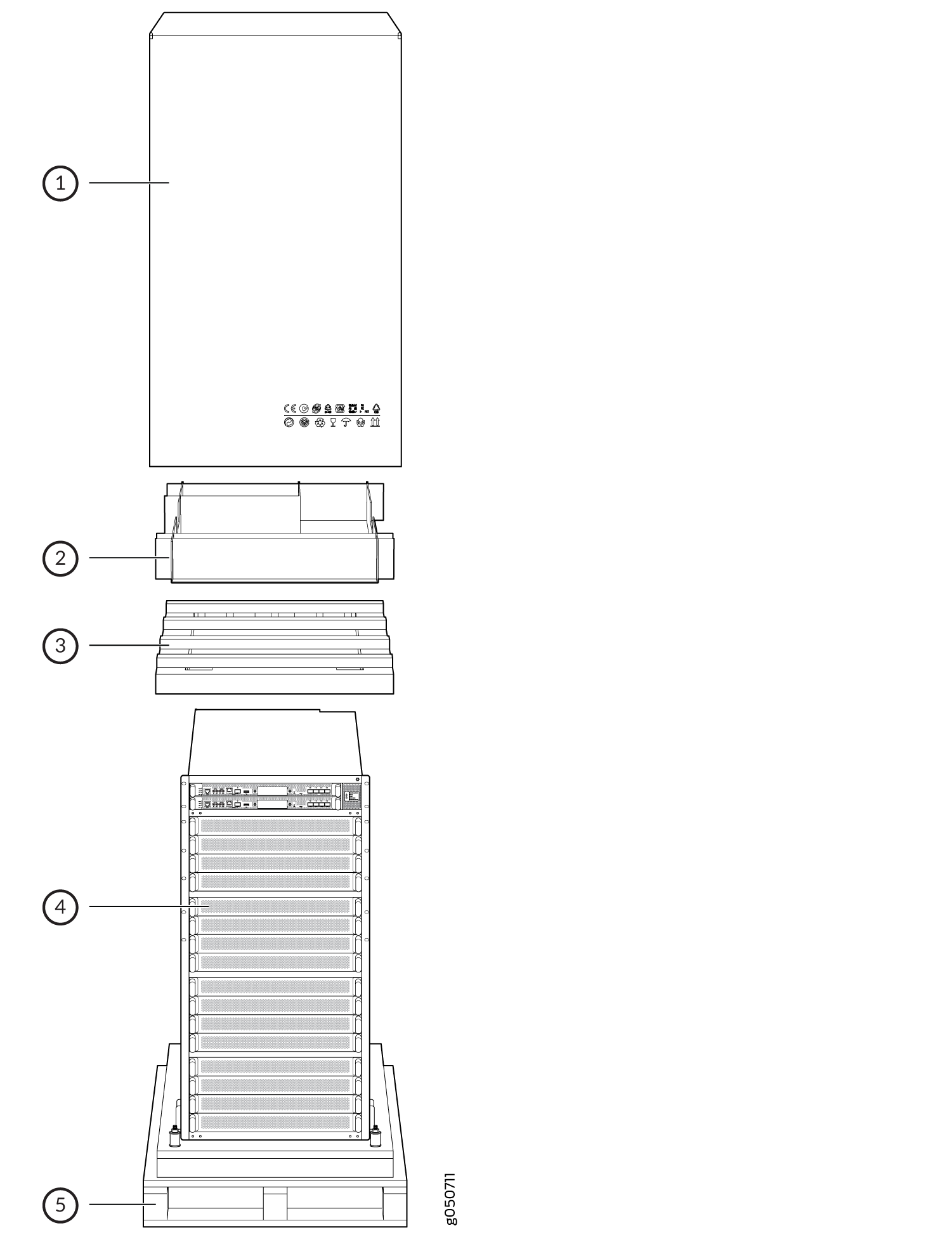
To pack a QFX10000 for shipping:
Packing QFX10000 Switch Components for Shipping
Before you begin packing a switch component, ensure that you have the following parts and tools available:
Antistatic bag, one for each component
Electrostatic discharge (ESD) grounding strap
Do not stack switch components. Return individual components in separate boxes if they do not fit together on one level in the shipping box.
To pack and ship QFX10000 components:
- Place individual FRUs in antistatic bags.
- Use the original packing materials if they are available. If the original packing materials are not available, ensure the component is adequately packed to prevent damage during transit. The packing material you use must be able to support the weight of the component.
- Ensure that the components are adequately protected with packing materials and packed so that the pieces are prevented from moving around inside the carton.
- Close the top of the cardboard shipping box and seal it with packing tape.
- Write the RMA number on the exterior of the box to ensure proper tracking.