PTX5000 Host Subsystem
PTX5000 Host Subsystem Description
The PTX5000 host subsystem is comprised of a Routing Engine and Control Board working together as a unit. The host subsystem provides the routing and system management functions of the PTX5000. You can install one or two host subsystems. To operate, each host subsystem functions as a unit; the Routing Engine requires the corresponding Control Board, and vice versa.
We recommend that you install two host subsystems for redundant protection.
Each host subsystem has three LEDs, located on the upper left of the craft interface, which display the status of the host subsystem. In addition, there are LEDs on each Routing Engine and Control Board.
See Also
PTX5000 Routing Engine Description
- Routing Engine Slots
- Routing Engine Functions
- RE-DUO-C2600-16G Routing Engine Components
- RE-PTX-X8-64G Routing Engine Components
- RE-PTX-X8-128G Routing Engine Components
- Routing Engine Boot Sequence
Routing Engine Slots
You can install one or two Routing Engines in the PTX5000. The Routing Engines install into the Control Boards labeled CB0 and CB1. If two Routing Engines are installed, one functions as the primary and the other acts as the backup. If the primary Routing Engine fails or is removed and the backup is configured appropriately, the backup restarts and becomes the primary.
Routing Engine Functions
The Routing Engine handles all routing protocol processes, as well as the software processes that control the PTX5000 router's interfaces, the chassis components, system management, and user access to the PTX5000. The routing and software processes run on top of a kernel that interacts with the Packet Forwarding Engine.
The Routing Engine constructs and maintains one or more routing tables. From the routing tables, the Routing Engine derives a table of active routes, called the forwarding table, which is then copied into the Packet Forwarding Engine. The design of the ASICs allows the forwarding table in the Packet Forwarding Engine to be updated without interrupting forwarding performance.
The Routing Engine includes the following functions and features:
Processing of routing protocol packets—The Routing Engine handles all packets that concern routing protocols, freeing the Packet Forwarding Engine to handle only packets that represent Internet traffic.
Software modularity—Because each software process is devoted to a different function and uses a separate process space, the failure of one process has little or no effect on the others.
In-depth Internet functionality—Each routing protocol is implemented with a complete set of Internet features and provides full flexibility for advertising, filtering, and modifying routes. Routing policies are set according to route parameters (for example, prefix, prefix lengths, and BGP attributes).
Scalability—Junos OS routing tables have been designed to hold all the routes in current networks with ample capacity for expansion. Additionally, Junos OS can efficiently support large numbers of interfaces and virtual circuits.
Management interface—Different levels of system management tools are provided, including the Junos OS command-line interface (CLI), the Junos XML management protocol, the craft interface, and SNMP.
Storage and change management—Configuration files, system images, and microcode can be held and maintained in primary and secondary storage systems, permitting local or remote upgrades.
Monitoring efficiency and flexibility—The PTX5000 supports functions such as alarm handling and packet counting on every port, without degrading packet-forwarding performance.
RE-DUO-C2600-16G Routing Engine Components
Each Routing Engine (shown in Figure 1) consists of the following components:
CPU—Runs Junos OS to maintain the routing tables and routing protocols.
DRAM—Provides storage for the routing and forwarding tables and for other Routing Engine processes.
EEPROM—Stores the serial number of the Routing Engine.
Interfaces for management access—Provide information about Routing Engine status to the external management devices (console, laptop, or terminal server) connected to the management ports on the Control Board.
1 — Extractor clips | 5 — USB LED |
2 — SSD and CompactFlash card slot cover | 6 — Offline button |
3 — LEDs—DISK1, DISK2, and CF | 7 — Online LED |
4 — USB port | 8 — Reset button |
The faceplate of the Routing Engine contains the following:
USB port USB—Provides a removable media interface through which you can install Junos OS manually. Junos OS supports USB versions 2.0 and 1.1.
CompactFlash card slot —Provides primary storage for software images, configuration files, and microcode.
Two solid-state disk slots Disk 1 and Disk 2—Provide secondary storage for log files, memory dumps, and rebooting the system if the CompactFlash card fails.
Note:Disk 2 is not currently supported.
Reset button—Reboots the Routing Engine when pressed.
Offline button—Takes the Routing Engine offline when pressed.
Extractor clips—Control the locking system that secures the Routing Engine.
LEDs—PTX5000 Routing Engine LEDs describes the functions of these LEDs.
For specific information about Routing Engine components (for
example, the amount of DRAM), issue the show chassis routing-engine command.
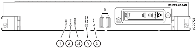
RE-PTX-X8-64G Routing Engine Components
1 — Extractor clips | 4 — RESET button |
2 — LEDs—DISK1, DISK2, and ONLINE | 5 — USB0 and USB1 ports |
3 — ONLINE/OFFLINE button | 6 — SSD card slot cover |
Each Routing Engine (shown in Figure 2) consists of the following components:
CPU—Runs Junos OS to maintain the routing tables and routing protocols. The CPU is an eight-core CPU with core frequency of 2.3 GHz.
DRAM—Provides storage for the routing and forwarding tables and for other Routing Engine processes.
EEPROM—Stores the serial number of the Routing Engine.
The faceplate of the Routing Engine contains the following:
Two USB ports USB0 and USB1—Provide a removable media interface through which you can install Junos OS manually. Junos OS supports USB versions 3.0, 2.0, and 1.1.
Two solid-state drive slots for the primary SSD SSD1 and the secondary SSD SSD2—Provide storage for software images, configuration files, microcode, log files, and memory dumps. The Routing Engine reboots the system from SSD2 when booting from SSD1 fails.
RESET button—Reboots the Routing Engine when pressed.
ONLINE/OFFLINE button—Takes the Routing Engine offline or brings it online when pressed.
Note:The ONLINE/OFFLINE button must be pressed for a minimum of 4 seconds for the power off or power on to occur.
Extractor clips—Control the locking system that secures the Routing Engine.
LEDs—PTX5000 Routing Engine LEDs describes the functions of these LEDs.
For specific information about Routing Engine components (for
example, the amount of DRAM), issue the show chassis routing-engine command.
RE-PTX-X8-128G Routing Engine Components
The RE-PTX-X8-128G Routing Engine has increased memory and storage to support virtualization. The Routing Engine is equipped with an 8 Core 2.3 GHz processor, 128GB Memory, and two 200GB SSDs. It also supports Secure Boot for enhanced boot security.
1 — Extractor clips | 4 — RESET button |
2 — LEDs—DISK1, DISK2, and ONLINE | 5 — USB0 and USB1 ports |
3 — ONLINE/OFFLINE button | 6 — SSD card slot cover |
Each Routing Engine (shown in Figure 3) consists of the following components:
CPU—Runs Junos OS to maintain the routing tables and routing protocols. The CPU is an eight-core CPU with core frequency of 2.3 GHz.
DRAM—Provides storage for the routing and forwarding tables and for other Routing Engine processes.
EEPROM—Stores the serial number of the Routing Engine.
The faceplate of the Routing Engine contains the following:
Two USB ports USB0 and USB1—Provide a removable media interface through which you can install Junos OS manually. Junos OS supports USB versions 3.0, 2.0, and 1.1.
Two solid-state drive slots for the primary SSD SSD1 and the secondary SSD SSD2—Provide storage for software images, configuration files, microcode, log files, and memory dumps. The Routing Engine reboots the system from SSD2 when booting from SSD1 fails.
RESET button—Reboots the Routing Engine when pressed.
ONLINE/OFFLINE button—Takes the Routing Engine offline or brings it online when pressed.
Note:The ONLINE/OFFLINE button must be pressed for a minimum of 4 seconds for the power off or power on to occur.
Extractor clips—Control the locking system that secures the Routing Engine.
LEDs—PTX5000 Routing Engine LEDs describes the functions of these LEDs.
For specific information about Routing Engine components (for
example, the amount of DRAM), issue the show chassis routing-engine command.
Routing Engine Boot Sequence
The Routing Engine boots from the storage media in this order: the USB device (if present), the CompactFlash card CF (if present), the disk (if present) in slot 1 Disk1, and then the LAN.
Disk2 is not currently supported on RE-DUO-C2600-16G but is supported on RE-PTX-X8-64G.
There is no support for the CompactFlash card in RE-PTX-X8-64G and RE-PTX-X8-128G.
Booting in an RE-PTX-X8-64G and RE-PTX-X8-128G Routing Engines follows this sequence—the USB device, SSD1, SSD2, and LAN. SSD1 is the primary boot device. The boot sequence is tried twice for SSD1 and SSD2.
PTX5000 Routing Engine LEDs
Routing Engine LEDs (RE-DUO-C2600-16G)
Three LEDs—Online, CF, and Disk1—indicate the status of the Routing Engine (see Figure 4).
1 — CF and Disk1 LEDs. Disk 2 is not used. | 3 — Online LED |
2 — USB LED |
The LEDs on the Routing Engine do not necessarily indicate routing-related activity.
Label |
Color |
State |
Description |
|---|---|---|---|
Online |
Green |
On steadily |
Routing Engine is functioning normally. |
Red |
On steadily |
Routing Engine is not functioning normally. |
|
– |
Off |
Routing Engine is not online or not functioning normally. |
|
Disk1 |
Green |
On steadily |
An SSD is installed in the Disk1 slot in the Routing Engine. |
Blinking |
Indicates disk activity. |
||
– |
Off |
There is no disk activity. |
|
Disk2 |
– |
Off |
Note:
This LED is not used. |
CF |
Green |
On steadily |
A CompactFlash card is installed in the Routing Engine. |
Blinking |
Indicates activity for the CompactFlash card. |
||
– |
Off |
There is no activity for the CompactFlash card. |
|
USB |
Yellow |
On steadily |
A USB device connected to the Routing Engine. |
– |
Off |
There is no USB device connected to the Routing Engine. |
Routing Engine LEDs (RE-PTX-X8-64G and RE-PTX-X8-128G)
1 — DISK1 LED | 4 — ONLINE/OFFLINE button |
2 — DISK2 LED | 5 — RESET button |
3 — ONLINE LED |
Label |
Color |
State |
Description |
|---|---|---|---|
ONLINE |
Green |
On steadily |
Routing Engine is functioning normally. |
Green |
Blinking slowly |
Routing Engine is in the process of booting BIOS and the host OS. |
|
Blinking rapidly |
Routing Engine is in the process of booting Junos OS. |
||
_ |
Off |
Routing Engine is not online or not functioning normally |
|
DISK1 |
Green |
Blinking |
Indicates the presence of disk activity. |
_ |
Off |
There is no disk activity. |
|
DISK2 |
Green |
Blinking |
Indicates the presence of disk activity. |
_ |
Off |
There is no disk activity. |
Routing Engines Supported on PTX Series Routers
The following tables list the Routing Engines that each PTX Series router supports and the Routing Engine specifications.
- PTX1000 Routing Engines
- PTX3000 Routing Engines
- PTX5000 Routing Engines
- PTX10008 and PTX10016 Routing Engines
- PTX Series Routing Engine Specifications
PTX1000 Routing Engines
Table 3 lists the Routing Engine supported on the PTX1000.
The PTX1000 supports 64-bit Junos OS only.
Model Number |
Name in CLI Output |
First Supported Junos OS Release |
Management Ethernet Interface |
Internal Ethernet Interface |
|---|---|---|---|---|
Built-in Routing Engine |
|
|
em0 |
bme0 em1 |
PTX3000 Routing Engines
Table 4 lists the Routing Engines supported on the PTX3000.
The PTX3000 supports 64-bit Junos OS only.
Model Number |
Name in CLI Output |
First Supported Junos OS Release |
Management Ethernet Interface |
Internal Ethernet Interface |
|---|---|---|---|---|
RE-DUO-C2600-16G |
|
13.2R2 |
em0 |
ixgbe0 ixgbe1 |
RCB-PTX-X6-32G |
|
16.1R4 17.1R1 This Routing Engine does not support Junos OS Release 16.2. |
em0 |
ixlv0 ixlv1 |
PTX5000 Routing Engines
Table 5 lists the Routing Engines supported on the PTX5000.
PTX5000 supports 64-bit Junos OS only.
The PTX5000 router supports two midplanes. The midplane identified as
Midplane-8Sin the CLI output is supported in Junos OS releases, 12.1X48, 12.3, and 13.2. The enhanced midplane, identified asMidplane-8SePis supported from Junos OS release 14.1 onwards.The RE-DUO-2600 routing engine with Junos OS 13.2 or earlier is not supported on the PTX5000BASE2 midplane.
Model Number |
Name in CLI Output |
First Supported Junos OS Release |
Management Ethernet Interface |
Internal Ethernet Interface |
|---|---|---|---|---|
RE-DUO-C2600-16G |
|
12.1X48 12.3 13.2 Note:
The PTX5000 does not support Junos OS Releases 12.1, 12.2, or 13.1. |
em0 |
ixgbe0 ixgbe1 |
RE-PTX-X8-64G |
|
15.1F4 16.1R1 |
em0 |
ixlv0 ixlv1 em1 |
RE-PTX-X8-128G |
|
18.1R1 |
em0 |
ixlv0 ixlv1 em1 |
PTX10008 and PTX10016 Routing Engines
Table 6 lists the Routing Engines supported on the PTX10008 and PTX10016 routers.
Model Number |
Name in CLI Output |
First Supported Junos OS Release |
Management Ethernet Interface |
Internal Ethernet Interface |
|---|---|---|---|---|
JNP10K-RE0 |
|
17.2R1 |
em0, em1 |
bme0 bme1 |
JNP10K-RE1 JNP10K-RE1-LT |
|
18.2R1 |
em0, em1 |
bme0 bme1 |
JNP10K-RE1-128 |
|
18.3R1 |
em0, em1 |
bme0 bme1 |
PTX Series Routing Engine Specifications
Table 7 lists the current specifications for Routing Engines supported on the PTX Series.
The memory listed in Table 7 indicates
the amount of total memory. To determine the amount of available memory,
issue the show chassis routing-engine CLI command.
Model Number |
Processor |
Memory |
Connection to Packet Forwarding Engines |
Disk |
Media |
|---|---|---|---|---|---|
RE-DUO-C2600-16G |
2.6 GHz |
16 GB |
Gigabit Ethernet |
SSD |
4-GB CompactFlash card |
RE-PTX-X8-64G (PTX5000 only) |
2.3 GHz |
64 GB |
10-Gigabit Ethernet |
Dual SSD |
– |
RE-PTX-X8-128G (PTX5000 only) |
2.3 GHz |
128 GB |
10-Gigabit Ethernet |
Dual SSD |
– |
RCB-PTX-X6-32G (PTX3000 only) |
2.0 GHz |
32 GB |
10-Gigabit Ethernet Note:
Each link can operate at 10-Gbps or 1-Gbps depending on the capability of the FPC. Some FPCs operate only at 1-Gbps. When there is a mix of RE-DUO-C2600-16G and RCB-PTX-X6-32G the links operate at 1- Gbps. |
Dual SSD |
– |
PTX1000 built-in Routing Engine |
2.5 GHz |
16 GB |
10-Gigabit Ethernet |
Dual SSD |
– |
JNP10K-RE0 |
2.5 GHz |
32 GB |
10-Gigabit Ethernet |
Dual SSD |
– |
JNP10K-RE1 JNP10K-RE1-LT |
2.3 GHz |
64 GB |
10-Gigabit Ethernet |
Dual SSD |
– |
JNP10K-RE1-128G |
2.3 GHz |
128 GB |
10-Gigabit Ethernet |
Dual SSD |
– |
See Also
PTX5000 Control Board Description
- Control Board Slots
- Control Board Function
- Control Board CB-PTX Components
- Control Board CB2-PTX Components
Control Board Slots
You can install up to two Control Boards in the PTX5000. Control Boards install into the rear of the chassis in the slots labeled CB0 and CB1. A Routing Engine installs directly into a slot on each Control Board. The Control Boards cannot function if a Routing Engine is not present.
If the PTX5000 contains a redundant host subsystem, one host subsystem functions as the primary and the other as its backup. If the primary fails or is removed, the backup becomes the primary. The backup becomes the primary automatically only if graceful Routing Engine switchover (GRES) is enabled. Otherwise, manual intervention is required for a host subsystem to acquire primary role.
Control Board Function
Each Control Board works with the Routing Engine to provide the following control and monitoring functions for the PTX5000:
Determining Routing Engine primary role
Controlling power and reset for the other PTX5000 components
Monitoring and controlling fan speed
Monitoring system status
Control Board CB-PTX Components
Each Control Board consists of the following components :
Ethernet switch used for intermodule communication
PCI bus to the Routing Engines
Switch Processor Mezzanine Board (SPMB)
Figure 6 shows the Control Board faceplate.
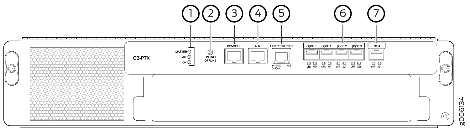
1 — MASTER, FAIL, and OK status LEDs | 5 — HOST/ETHERNET port |
2 — ONLINE/OFFLINE button | 6 — 10-Gigabit Ethernet ports labeled (X)GE 0 (X)GE 3 |
3 — CONSOLE port | 7 — Gigabit Ethernet port labeled GE 4 |
4 — AUX port |
The following components are located on the Control Board faceplate:
A slot for installation of the Routing Engine.
Three status LEDs—MASTER, FAIL, and OK—indicate the status of the Control Board.
ONLINE/OFFLINE button, located to the right of the status LEDs.
Three RJ-45 management ports for connecting the Routing Engine to external management devices. The management ports on each Control Board connect to the Routing Engine installed into that Control Board. From these management devices, you can use the CLI to configure and manage the PTX5000. Each Control Board includes the following ports:
HOST/ETHERNET—10/100/1000-Mbps Ethernet port for connecting to a management network. This port connects the Routing Engine through a copper 10/100/1000BASE-T Ethernet connection to a management LAN (or any other device that plugs into an Ethernet connection) for management of the PTX5000. The port uses an autosensing RJ-45 connector to support 10-Mbps, 100-Mbps, or 1-Gbps connections. Two small LEDs on the bottom edge of the port indicate the port speed and traffic on the port. The left LED is labeled Y=10/100 G=1000, and the right LED is labeled ACT.
CONSOLE—One copper 9600 baud port for connecting the Routing Engine to a system console through a copper cable with RJ-45 connectors.
AUX— One copper 9600 baud port for connecting the Routing Engine to a laptop, modem, or other auxiliary device through a copper cable with RJ-45 connectors.
Note:If a PTX5000 contains two host subsystems, connect both Control Boards to your external management network.
Four 10-Gigabit Ethernet SFP+ fiber-optic ports— labeled (X)GE0 through (X)GE3—located to the right of the management ports.
Two port LEDs—labeled LINK and ACT—located below the 10-Gigabit Ethernet ports port indicate the port speed and activity.
Note:These ports are reserved for future use.
Gigabit Ethernet SFP fiber-optic or copper port— labeled GE4—located to the right of the 10-Gigabit Ethernet ports.
Note:This port is reserved for future use.
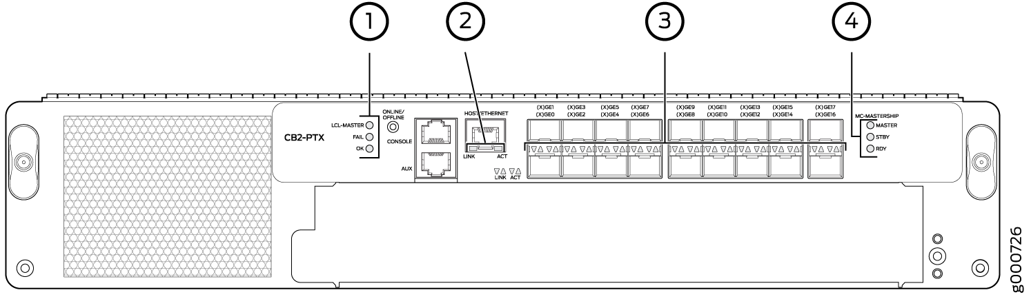
Control Board CB2-PTX Components
Each Control Board consists of the following components:
Ethernet switch used for intermodule communication
PCI Express switch to connect to the SIBs
Switch Processor Mezzanine Board (SPMB)
Figure 7 shows the Control Board faceplate.
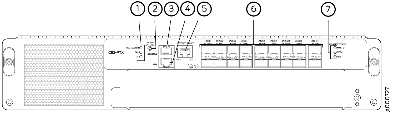
1 — LCL-MASTER, FAIL, and OK status LEDs | 5 — HOST/ETHERNET port |
2 — ONLINE/OFFLINE button | 6 — Gigabit Ethernet ports labeled (X)GE 0 through (X)GE 17 |
3 — CONSOLE port | 7 — MASTER, STBY, and RDY status LEDs |
4 — AUX port |
The following components are located on the Control Board faceplate:
A slot for installation of the Routing Engine.
Three status LEDs—LCL-MASTER, FAIL, and OK—indicate the status of the Control Board.
ONLINE/OFFLINE button, located to the right of the status LEDs.
Three RJ-45 management ports for connecting the Routing Engine to external management devices. The management ports on each Control Board connect to the Routing Engine installed into that Control Board. From the external management devices, you can use the CLI to configure and manage the PTX5000. Each Control Board includes the following ports:
HOST/ETHERNET—10/100/1000-Mbps Ethernet port for connecting to a management network. This port connects the Routing Engine through a copper 10/100/1000BASE-T Ethernet connection to a management LAN (or any other device that plugs into an Ethernet connection) for management of the PTX5000. The port uses an autosensing RJ-45 connector to support 10-Mbps, 100-Mbps, or 1-Gbps connections. Two small LEDs on the bottom edge of the port indicate the port speed and traffic on the port. The left LED is labeled LINK, and the right LED is labeled ACT to indicate port speed and activity.
CONSOLE—One 9600-baud-rate console port for connecting the Routing Engine to a system console through a copper cable with RJ-45 connectors.
AUX— One 9600-baud-rate console port for connecting the Routing Engine to a laptop, modem, or other auxiliary device through a copper cable with RJ-45 connectors.
Note:If a PTX5000 contains two host subsystems, connect both Control Boards to your external management network.
Eighteen 10-Gigabit Ethernet SFP+ fiber-optic ports—labeled (X)GE0 through (X)GE17—located to the right of the management ports. These ports are reserved for future use. However, (X)GE14 and (X)GE15 are configured as 1-Gigabit Ethernet ports.
MASTER, STBY, and RDY LEDs—For multichassis applications. These LEDs are reserved for future use.
PTX5000 Control Board LEDs
Three LEDs located to the left of the online/offline button indicate the status of the Control Board. Table 8 and Table 10 describes the functions of the Control Board LEDs.
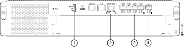
1 — MASTER, FAIL, and OK status LEDs | 3 — LINK and ACT LEDs for the 10-Gigabit Ethernet ports labeled (X)GE 0 (X)GE 3 |
2 — Y=10/100 G=1000 and ACT LEDs for the HOST/ETHERNET port | 4 — LINK and ACT LEDs for the Gigabit Ethernet port labeled GE 4 |
Label |
Color |
State |
Description |
|---|---|---|---|
MASTER |
Blue |
On steadily |
Control Board is functioning as the primary. |
– |
Off |
Control Board is functioning as the backup. |
|
FAIL |
Yellow |
On steadily |
Control Board has failed. |
– |
Off |
No faults have been detected on the Control Board. |
|
OK |
Green |
On steadily |
Control Board is online and is functioning normally. |
– |
Off |
Control Board is offline. |
Port |
Label |
Color |
State |
Description |
|---|---|---|---|---|
HOST/ETHERNET |
Y=10/100 G=1000 |
Green |
On steadily |
1-Gbps connection. |
Yellow |
On steadily |
10/100-Mbps connection. |
||
– |
Off |
Control Board is offline. |
||
ACT |
Green |
On steadily |
Traffic is passing through the port. |
|
– |
Off |
No traffic is passing through the port. |
||
(X)GE0 through (X)GE3 |
LINK |
Green |
– |
Note:
These ports are reserved for future use. |
ACT |
Green |
– |
Note:
These ports are reserved for future use. |
|
GE4 |
LINK |
Green |
– |
Note:
This port is reserved for future use. |
ACT |
Green |
– |
Note:
This port is reserved for future use. |
1 — LCL-MASTER, FAIL, and OK status LEDs | 3 — Link and activity LEDs for the Gigabit Ethernet ports labeled (X)GE 0 through (X)GE 17 |
2 — LINK and ACT LEDs for the HOST/ETHERNET port | 4 — MASTER, STBY, and RDY status LEDs. These LEDs are reserved for future use for multichassis applications. |
Label |
Color |
State |
Description |
|---|---|---|---|
LCL-MASTER |
Blue |
On steadily |
Control Board is functioning as the primary. |
– |
Off |
Control Board is functioning as the backup. |
|
FAIL |
Yellow |
On steadily |
Control Board has failed. |
– |
Off |
No faults are detected on the Control Board. |
|
OK |
Green |
On steadily |
Control Board is online and is functioning normally. |
– |
Off |
Control Board is offline. |
|
MC-MASTERSHIP LEDs |
|||
MASTER |
Off |
These LEDs are reserved for future use for multichassis applications. |
|
STBY |
Off |
||
RDY |
Off |
||
Port |
Label |
Color |
State |
Description |
|---|---|---|---|---|
HOST/ETHERNET |
LINK |
Green |
On steadily |
1-Gbps connection. |
Yellow |
On steadily |
100-Mbps connection. |
||
– |
Off |
10-Mbps connection (If theACT LED is blinking green) |
||
– |
Off |
Offline |
||
ACT |
Green |
Blinking |
Indicates activity. 1-Gbps connection. |
|
Green |
Off |
Indicates no activity. |
||
(X)GE0 through (X)GE17 |
LINK |
Green |
On steadily |
Note:
These ports are reserved for future use. (X)GE14 and (X)GE15 are configured as 1-Gigabit Ethernet ports. |
ACT |
Green |
Blinking |
Note:
These ports are reserved for future use. (X)GE14 and (X)GE15 are configured as 1-Gigabit Ethernet ports. |