Maintaining the PTX5000 Host Subsystem
Maintaining the PTX5000 Host Subsystem
Purpose
For optimum PTX5000 performance, verify the condition of the host subsystem. Each host subsystem comprises a Routing Engine and an adjacent Control Board functioning together.
Action
On a regular basis:
Check the host subsystem LEDs OK and Fail on the craft interface for (HOST0 and HOST1. For more information about the LEDs on the craft interface, see PTX5000 Craft Interface LEDs.
During normal operations:
The green host subsystem OK LED on the craft interface is lit.
The red host subsystem FAIL LED on the craft interface is not lit.
Understanding the Effect of Taking the PTX5000 Host Subsystem Offline
- Taking a Nonredundant Host Subsystem Offline
- Taking a Backup Host Subsystem Offline
- Taking a Primary Host Subsystem Offline
Taking a Nonredundant Host Subsystem Offline
Taking a nonredundant host subsystem offline shuts down the PTX5000.
Taking a Backup Host Subsystem Offline
Taking a backup host subsystem offline does not interrupt the functioning of the PTX5000. The backup host subsystem is hot-removable and hot-insertable.
Taking a Primary Host Subsystem Offline
Removal or failure of the primary Routing Engine affects forwarding and routing based on the high availability configuration.
For information about configuring high availability features such as graceful Routing Engine switchover (GRES) and nonstop active routing (NSR), see the High Availability User Guide.
Both Routing Engines should be running the same Junos OS release.
If the backup Routing Engine's configuration differs from the former primary's configuration, router performance might change. For the most predictable performance, configure the two Routing Engines identically, except for parameters unique to each Routing Engine.
To configure Routing Engine-specific parameters and still use
the same configuration on both Routing Engines, include the appropriate
configuration statements under the re0 and re1 statements at the [edit groups] hierarchy level and use
the apply-groups statement. For instructions, see the Junos OS Administration Library.
When a primary host subsystem is taken offline or during a primary role switch, the backup host subsystem becomes the primary, and the backup Routing Engine assumes Routing Engine functions. The primary host subsystem is hot-pluggable. During the switchover to the backup Routing Engine:
Dual Routing Engines without any high availability features enabled—Traffic is interrupted while the Packet Forwarding Engine is reinitialized. Packet forwarding halts while the standby Routing Engine becomes the primary and the Packet Forwarding Engine components reset and connect to the new primary Routing Engine. All kernel and forwarding processes are restarted. When the switchover to the new primary Routing Engine is complete, routing convergence takes place and traffic is resumed.
GRES is supported on Junos OS Release 12.1X48 and later.
GRES is enabled—Graceful Routing Engine switchover preserves interface and kernel information. Traffic is not interrupted. The backup Routing Engine immediately assumes Routing Engine functions and there is no interruption to packet forwarding. However, graceful Routing Engine switchover does not preserve the control plane. Neighboring routers detect that the PTX5000 has restarted and react to the event in a manner prescribed by individual routing protocol specifications. To preserve routing without interruption during a switchover, graceful Routing Engine switchover must be combined with nonstop active routing.
Nonstop active routing is supported on Junos OS Release 12.1X48R3 and later.
Nonstop active routing is enabled (graceful Routing Engine switchover must be configured for nonstop active routing to be enabled)—Nonstop active routing supports Routing Engine switchover without alerting peer nodes that a change has occurred. Nonstop active routing uses the same infrastructure as graceful Routing Engine switchover to preserve interface and kernel information. However, nonstop active routing also preserves routing information and protocol sessions by running the routing protocol process (rpd) on both Routing Engines. In addition, nonstop active routing preserves TCP connections maintained in the kernel.
Graceful restart is configured—Graceful restart provides extensions to routing protocols so that neighboring helper routers restore routing information to a restarting router. These extensions signal neighboring routers about the graceful restart and prevent the neighbors from reacting to the router restart and from propagating the change in state to the network during the graceful restart period. Neighbors provide the routing information that enables the restarting router to stop and restart routing protocols without causing network reconvergence. Neighbors are required to support graceful restart. The routing protocol process (rpd) restarts. A graceful restart interval is required. For certain protocols, a significant change in the network can cause graceful restart to stop.
See Also
Maintaining the PTX5000 Routing Engines
Purpose
For optimum performance, verify the condition of the Routing Engines.
Action
On a regular basis:
Check the host subsystem LEDs on the craft interface. During normal operations, the OK LED is lit green, and the FAIL LED is not lit. See PTX5000 Craft Interface LEDs.
Check the LEDs on the Routing Engine. During normal operation, the ONLINE LED on each Routing Engine is lit green, indicating that the Routing Engine is functional. See PTX5000 Routing Engine LEDs.
Look at the LCD display on the craft interface to view information about the status of the Routing Engines.
Issue the
show chassis routing-enginecommand to verify that the Routing Engines are operating properly.
Replacing a PTX5000 RE-DUO-C2600 Routing Engine
- Taking the PTX5000 Host Subsystem Offline
- Removing a PTX5000 Routing Engine
- Installing a PTX5000 Routing Engine
Taking the PTX5000 Host Subsystem Offline
Before you replace a Routing Engine, you must take the host subsystem offline. The host subsystem is taken offline and brought online as a unit. Be aware of the effect of taking a host subsystem offline on traffic, forwarding, and routing. See Understanding the Effect of Taking the PTX5000 Host Subsystem Offline.
To take a host subsystem offline:
Removing a PTX5000 Routing Engine
The PTX5000 can have one or two Routing Engines. They are located in a slot inside the Control Board below the SIBs in the rear of the chassis. Each Routing Engine can weigh up to 2.8 lb (1.3 kg).
To remove a Routing Engine (see Figure 1):
- Place an electrostatic bag or antistatic mat on a flat, stable surface.
- Attach an electrostatic discharge (ESD) grounding strap to your bare wrist, and connect the strap to one of the ESD points on the chassis.
- Take the host subsystem offline.
- Press the red tabs on the ejector handles on both sides of the Routing Engine faceplate.
- Flip the ejector handles outward to unseat the Routing Engine.
- Grasp the Routing Engine by the ejector handles and slide it about halfway out of the chassis.
- Place one of your hands underneath the Routing Engine to support it and slide it completely out of the chassis.
- Place the Routing Engine on the antistatic mat.
Installing a PTX5000 Routing Engine
Replacing a CompactFlash Card in a PTX5000 Routing Engine
- Removing a CompactFlash Card from a PTX5000 Routing Engine
- Installing a CompactFlash Card in a PTX5000 Routing Engine
- Copying the Junos OS to the CompactFlash Card in a PTX5000 Routing Engine
Removing a CompactFlash Card from a PTX5000 Routing Engine
The CompactFlash card is located in the slot labeled CompactFlash on the Routing Engine faceplate. To remove the CompactFlash card (see Figure 3):
Installing a CompactFlash Card in a PTX5000 Routing Engine
To install a CompactFlash card (see Figure 4):
Copying the Junos OS to the CompactFlash Card in a PTX5000 Routing Engine
After installing the CompactFlash card for the first time, you must copy the software from the Routing Engine's solid-state disk (SSD) to the CompactFlash card.
To copy software to the CompactFlash card:
- On the console or other management device connected to
the Routing Engine, enter CLI operational mode, and copy the currently
running and active file system partitions on the router to standby
partitions on the CompactFlash card. Issue the
request system snapshot partitioncommand. - Wait until a message appears on the console confirming that the snapshot partition procedure is complete.
- Issue the
request system rebootcommand to reboot the router's software. - Issue the
show system boot-messagescommand to verify that the CompactFlash card is listed as the primary boot device. The output lists the devices mounted. The CompactFlash card is located atad0.
Replacing an SSD Drive on a RE-DUO-C2600-16G
- Removing an SSD Drive From a RE-DUO-C2600-16G
- Installing an SSD Drive in a RE-DUO-C2600-16G
- Copying the Junos OS to the Solid-State Disk in a PTX5000 Routing Engine
Removing an SSD Drive From a RE-DUO-C2600-16G
The solid-state disk (SSD) drive is located in the slot labeled Disk1 on the Routing Engine faceplate.
The Disk 2 slot is not currently supported.
To remove an SSD drive from a Routing Engine (see Figure 5):
Installing an SSD Drive in a RE-DUO-C2600-16G
To install an SSD drive in a Routing Engine (see Figure 6):
Copying the Junos OS to the Solid-State Disk in a PTX5000 Routing Engine
After installing a solid-state disk (SSD) for the first time, you must copy the software from the Routing Engine's CompactFlash card to the SSD drive.
To copy software to the SSD drive:
- On the console or other management device connected to the Routing Engine, enter CLI operational mode.
- Partition the SSD drive. Issue the
request system partition hard-diskcommand. - Wait until a message appears on the console confirming that the partition procedure is complete.
- Reboot the router's software. Issue the
request system rebootcommand. - Back up the currently running and active file system partitions
on the router to standby partitions that are not running. Issue the
request system snapshotcommand.issue therequest system snapshotcommand. - Wait until a message appears on the console confirming that the snapshot procedure is complete.
- Reboot the router's software again. Issue the
request system rebootcommand. - Verify that the SSD drive is listed as the secondary boot
device. The output lists the devices mounted. The SSD drive is located
at
ad1. issue theshow system boot-messagescommand.
Replacing a PTX5000 RE-PTX-X8-64G Routing Engine
To replace the RE-PTX-X8-64G Routing Engine, perform the following procedures:
- Taking the Host Subsystem Offline
- Removing the Routing Engine
- Installing the Routing Engine RE-PTX-X8-64G
Taking the Host Subsystem Offline
Before you replace a Routing Engine, you must take the host subsystem offline. The host subsystem is taken offline and brought online as a unit. Be aware of the effect of taking a host subsystem offline on traffic, forwarding, and routing. See Understanding the Effect of Taking the PTX5000 Host Subsystem Offline.
To take a host subsystem offline:
Determine whether the Routing Engine to be replaced is currently functioning as the primary or as the backup, using one of the following methods:
Check the HOST 0 and HOST 1 LEDs on the craft interface. If the green MASTER LED is lit, the corresponding host subsystem is functioning as the primary.
Check the MASTER LED on the Control Board. If the blue MASTER LED is lit, the host subsystem is functioning as the primary.
Issue the
show chassis routing-enginecommand. The primary Routing Engine is designatedMasterin theCurrent statefield.user@host> show chassis routing-engine user@host> show chassis routing-engine Routing Engine status: Slot 0: Current state Master Election priority Master (default) ...
If the Routing Engine to be replaced is currently functioning as the primary, switch it to backup by using the CLI command:
user@host> request chassis routing-engine master switch
warning: Traffic will be interrupted while the PFE is re-initialized
Toggle mastership between Routing Engines ? [yes,no] (no) yes

Resolving mastership...
Complete. The other Routing Engine becomes the master.
Halt the host subsystem.
user@host> request vmhost halt

*** FINAL System shutdown message from user@host ***
System going down IMMEDIATELY
Terminated
...
syncing disks... 11 8 done
The operating system has halted.
Please press any key to reboot.
Note:The
request vmhost haltcommand halts the Routing Engine on the control plane from which it was issued. The command shuts down the Routing Engine cleanly, so its state information is preserved. The SIBs might continue forwarding traffic for approximately 5 minutes after therequest vmhost haltcommand has been issued. To reboot a Routing Engine that has been halted, you must connect through the console.On the console or other management device connected to the other Routing Engine, enter CLI operational mode and issue the following command.
user@host> request chassis cb offline slot n
n is 0 or 1 for the slot number of the host subsystem being taken offline.
Verify that the Control Board is offline:
user@host> show chassis environment cb
Removing the Routing Engine
The PTX5000 can have one or two Routing Engines. They are located in a slot inside the Control Board below the SIBs in the rear of the chassis. Each Routing Engine can weigh up to 2.6 lb (1.2 kg).
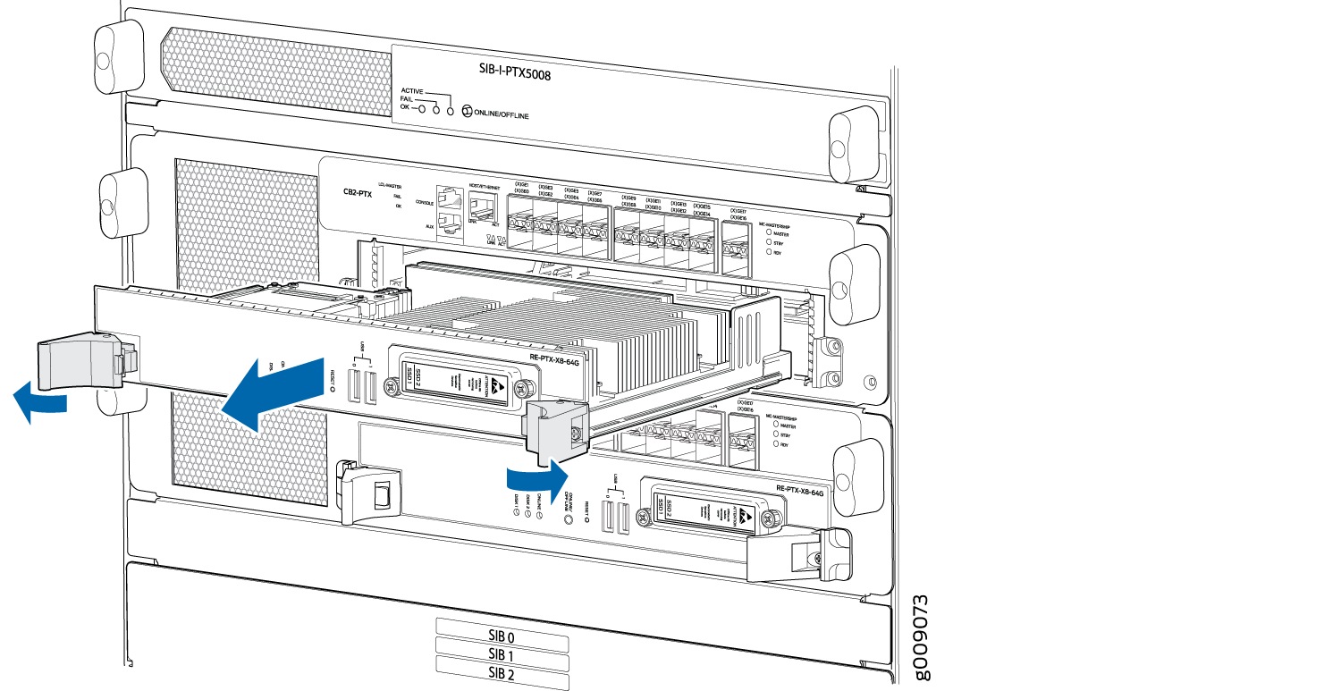
Remove the Routing Engine from the chassis:
- Power off the Routing engine gracefully.
- Place an electrostatic bag or antistatic mat on a flat, stable surface. Attach an electrostatic discharge (ESD) grounding strap to your bare wrist and connect the strap to one of the ESD points on the chassis.
- Verify that the Routing Engine LEDs are off. Loosen the captive screws on the top and bottom of the Routing Engine.
- Grasp the Routing Engine by the ejector handles, and slide it about halfway out of the chassis.
- Place one hand underneath the Routing Engine to support it, and slide it completely out of the chassis. Place the Routing Engine on an antistatic mat.
Installing the Routing Engine RE-PTX-X8-64G
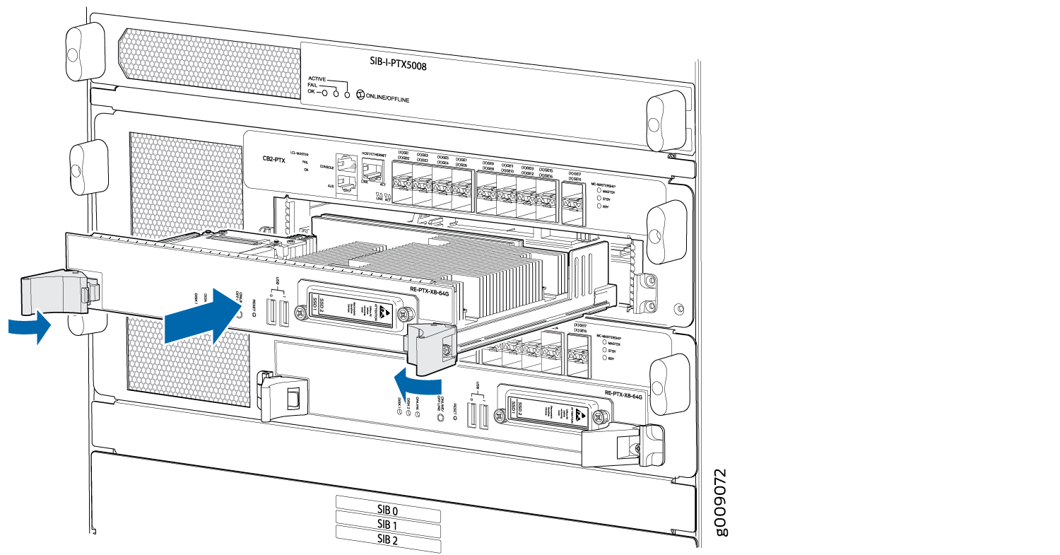
While installing, ensure that you install the Routing Engine RE-PTX-X8-64G into the Control Board CB2-PTX only.
To install a Routing Engine (see Figure 8):
Attach an ESD grounding strap to your bare wrist, and connect the strap to one of the ESD points on the chassis.
Ensure that the ejector handles are not in the locked position. If necessary, press the red tabs and flip the ejector handles outward.
Place one hand underneath the Routing Engine to support it. With the other hand, grasp one of the ejector handles on the faceplate.
Carefully align the sides of the Routing Engine with the guides inside the opening on the Control Board.
Slide the Routing Engine into the chassis until you feel resistance, and then press the Routing Engine's faceplate until it engages the connectors.
Press both the ejector handles inward to seat the Routing Engine.
Reconnect the cables and verify that the Routing Engine is installed correctly and functioning properly:
Verify that the green ONLINE LED lights steadily.
Verify the status of the Routing Engine using the
show chassis routing-enginecommand.
The Routing Engine might require several minutes to boot. If the PTX5000 is powered on and the Routing Engine's corresponding Control Board is functioning normally, the Routing Engine comes online automatically.
Replacing an SSD Drive on a RE-PTX-X8-64G
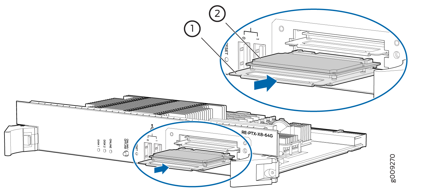
Each RE-PTX-X8-64G Routing Engine supports two solid-state disk (SSD) drives specified by Juniper Networks. The RE-PTX-X8-64G ships with two SSD drives installed in the slot labeled DISK1 and DISK2. Figure 9 shows the arrangement of storage drive slots on a RE-PTX-X8-64G Routing Engine.
64GB slim SATA SSD drive has been verified to work in the RE-PTX-X8-64G Routing Engine.
To replace a SSD drive:
- Remove the SSD drive.Figure 10: Removing the SSD Drive From a RE-PTX-X8-64G
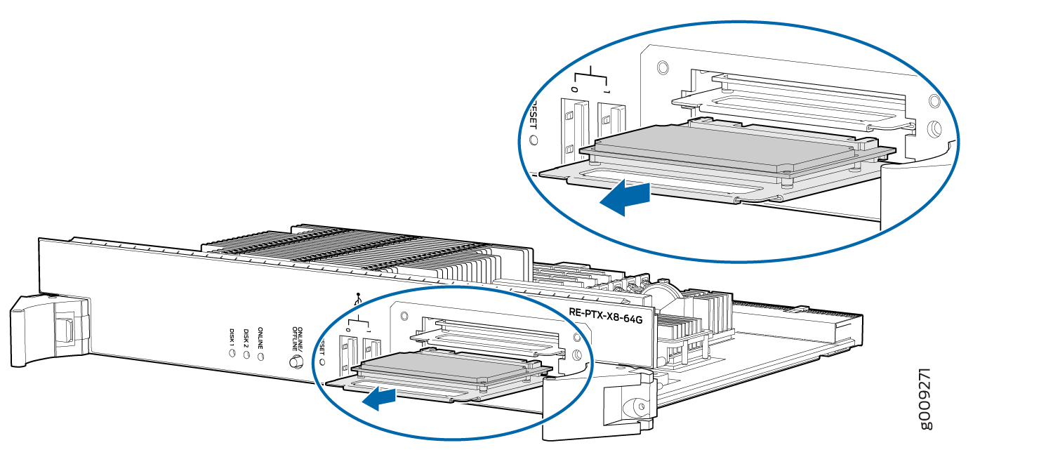
1 — Carrier | 2 — SSD drive |
Maintaining the PTX5000 Control Boards
Purpose
For optimum performance, verify the condition of the Control Boards.
Action
On a regular basis:
Check the host subsystem LEDs on the craft interface. See PTX5000 Craft Interface LEDs.
During normal operations:
The green host subsystem OK LED on the craft interface is lit.
The red host subsystem FAIL LED on the craft interface is not lit.
Look at the LEDs on the Control Board faceplates to see information about the Control Boards.
During normal operations:
The green OK LED on the Control Board faceplate is lit.
The yellow FAIL LED on the Control Board faceplate is not lit.
Issue the
show chassis environment cbcommand to verify that the Control Boards are operating properly.
Replacing a PTX5000 Control Board
- Taking the PTX5000 Host Subsystem Offline
- Removing a PTX5000 Control Board
- Installing a PTX5000 Control Board
Taking the PTX5000 Host Subsystem Offline
Before you replace a Control Board, you must take the host subsystem offline. The host subsystem is taken offline and brought online as a unit. Be aware of the effect of taking a host subsystem offline on traffic, forwarding, and routing. See Understanding the Effect of Taking the PTX5000 Host Subsystem Offline.
To take a host subsystem offline:
Removing a PTX5000 Control Board
To remove a Control Board (see Figure 13):
Installing a PTX5000 Control Board
To install a Control Board (see Figure 14):
Ensure that you Install the Routing Engine RE-DUO-C2600-16G into the Control Board CB-PTX and the Routing Engine RE-PTX-X8-64G into the Control Board CB2-PTX only.
Replacing a PTX5000 Management Console or Auxiliary Port Cable
- Removing a Management Console or Auxiliary Port Cable
- Installing a Management Console or Auxiliary Port Cable
Removing a Management Console or Auxiliary Port Cable
To remove a cable from the console or auxiliary port (see Figure 16):
- Attach an electrostatic discharge (ESD) grounding strap to your bare wrist, and connect the strap to one of the ESD points on the chassis.
- Turn off the power to the console or auxiliary device.
- Pull the cable connector straight out of the port.
- Disconnect the cable from the console or auxiliary device.
1 — Console port | 2 — Auxiliary port |
Installing a Management Console or Auxiliary Port Cable
To install a management console or auxiliary device cable:
- Attach an electrostatic discharge (ESD) grounding strap to your bare wrist, and connect the strap to one of the ESD points on the chassis.
- If necessary, turn off the power to the console or auxiliary device.
- Plug one end of a copper cable with RJ-45 connectors into the CONSOLE or AUXILIARY port on the Control Board in slot CB0. This port connects to the Routing Engine installed into the Control Board in slot CB0.
- Attach the other end of the cable to the console or auxiliary device.
- Plug one end of another copper cable with RJ-45 connectors into the CONSOLE or AUXILIARY port on CB1. This port connects to the Routing Engine installed into the control in slot CB1.
- Attach the other end of the cable to the console or auxiliary device.
Replacing a PTX5000 Management Ethernet Cable
Removing a PTX5000 Management Ethernet Cable
To remove a management Ethernet cable:
- Attach an electrostatic discharge (ESD) grounding strap to your bare wrist, and connect the strap to one of the ESD points on the chassis.
- Press the tab on the connector and pull the connector straight out of the HOST/ETHERNET port (see Figure 18). Figure 17 shows the connector.
- Disconnect the cable from the network device.
1 — Host/Ethernet port |
Installing a PTX5000 Management Ethernet Cable
To install a Management Ethernet cable: