Remove the PTX10016 Router from the Rack
To power off and remove the PTX10016 router, read the following sections.
Power Off the PTX10016 Router
Before you power off the PTX10016 router:
Ensure that you have taken the necessary precautions to prevent electrostatic discharge (ESD) damage. See Prevention of Electrostatic Discharge Damage.
Ensure that you need not forward traffic through the router.
Ensure that you have the following parts and tools available:
An ESD grounding strap (provided in the accessory kit)
An external management device such as a PC
An RJ-45 to DB-9 rollover cable to connect the external management device to the console port on one of the RCBs
To power off the PTX10016 router:
-
Wrap and fasten one end of the ESD grounding strap around your bare wrist
and connect the other end of the strap to one of the ESD points on the
chassis. An ESD point is located next to the protective grounding terminal
and below PSU 9 on the rear of the PTX10016 chassis
(see Figure 1). An
ESD point is located above the status LED panel on the front of the PTX10016
chassis (see Figure 2).
Figure 1: ESD Point on the Rear of the PTX10016 Chassis
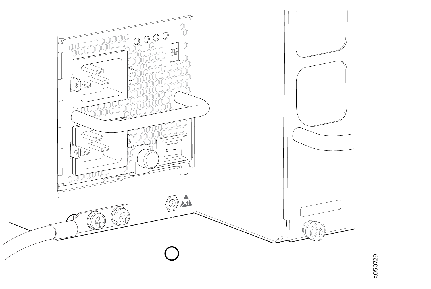 1—
1—ESD point
Figure 2: ESD Point on the Front of the PTX10016 Chassis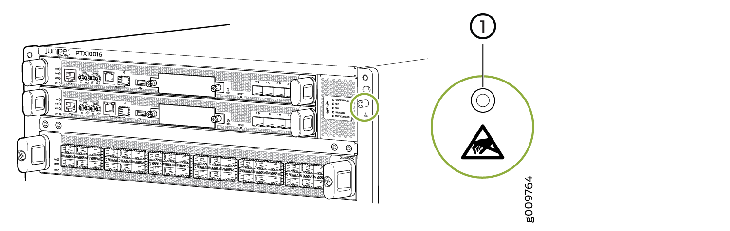 1—
1—ESD point
See Also
Remove the PTX10016 Router from a Four-Post Rack Using a Mechanical Lift
Before you remove the router using a lift:
-
Ensure that the rack is stable and secured to the building.
-
Ensure there is enough space to place the removed router in its new location and along the path to the new location. See PTX10016 Clearance Requirements for Airflow and Hardware Maintenance.
-
Review the chassis lifting guidelines described in PTX10016 Chassis Lifting Guidelines.
-
Ensure that the router is safely powered off (see Power Off the PTX10016 Router and Connect AC Power to the PTX10016 Router).
When removing more than one router chassis from a rack, remove the routers in order from top to bottom.
-
Ensure that you have the following parts and tools available to remove the router:
-
A mechanical lift rated for 1000 lb (453.6 kg)
-
A Phillips (+) screwdriver, number 2 or number 3, depending on the size of your rack mount screws
-
Because of the router's size and weight, we only recommend that you use a mechanical lift to remove the PTX10016.
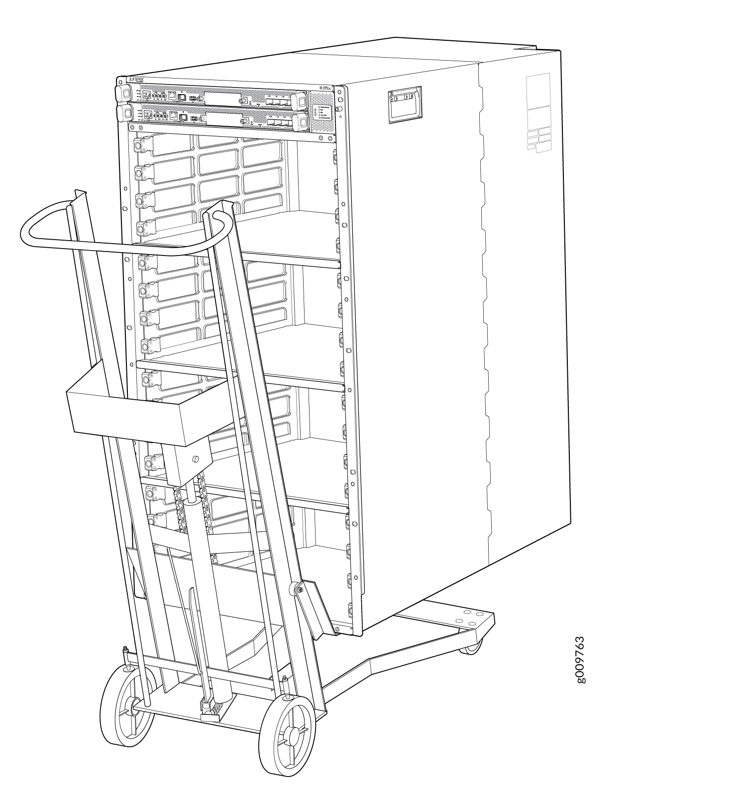
To remove the router using a mechanical lift (see Figure 3):
-
Use the lift to transport the router to its new location.
After moving the router to its new location, install the components in the chassis or store the components in antistatic bags.
Figure 3: Move the PTX10016 Router by Using a Mechanical Lift