Install and Remove PTX10004 Switch Fabric Components
Each PTX10004 router contains a minimum of three and a maximum of six Switch Interface Boards (SIBs) that are installed vertically, mid-chassis, between the line cards and the Routing and Control Boards (RCBs) in the front and the fan trays in the rear. To install or remove the switch interface boards in a the router, read the following sections.
How to Handle and Store PTX10004 SIBs
The PTX10004 SIBs have fragile components. To avoid damage to the SIBs, be sure you follow safe handling practices.
How to Hold a SIB
SIBs are installed vertically and should be held vertically until they are clear of the router before rotating them 90 degrees and placing them on an antistatic mat or placing them in an antistatic bag for storage. See Figure 1.
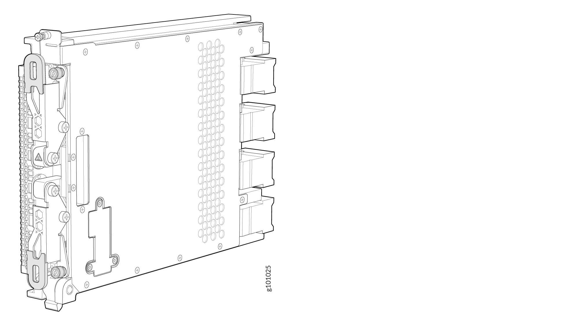
The proper method of holding a SIB is to:
How to Store a Switch Interface Board
You must store SIBs either in the chassis or in a spare shipping container, horizontally and sheet-metal side down. Do not stack these units on top of one another or on top of any other component. Place each unit separately in an antistatic bag or on an antistatic mat placed on a flat, stable surface.
Because these units are heavy and because antistatic bags are fragile, inserting the line card into the bag is best done by two people.
To insert a SIB into an antistatic bag:
- Hold the unit horizontally with the faceplate toward you.
- Slide the opening of the bag over the connector edge.
If you must insert the SIB into a bag by yourself:
-
Lay the unit horizontally on an antistatic mat that is on a flat, stable surface with the sheet-metal side down.
-
Orient the unit with the faceplate toward you.
-
Carefully insert the connector edge into the opening of the bag and pull the bag toward you to cover the unit.
Install a PTX10004 Switch Interface Board
A PTX10004 router has up to six SIBs that are located in the middle of the chassis behind the fan trays. SIB 0 through SIB 2 are located behind the left fan tray, and SIB 3 through SIB 5 are located behind the right fan tray. You must remove the appropriate fan tray to install a SIB. See Remove a PTX10004 Fan Tray.
Ensure that you have the following equipment with you before you install a SIB:
-
Antistatic bag or antistatic mat
-
Electrostatic discharge (ESD) grounding strap
-
Phillips (+) number 2 screwdriver (optional)
To install a SIB:
-
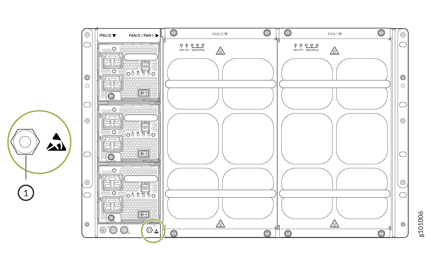
Wrap and fasten one end of the ESD grounding strap around
your bare wrist and connect the other end of the strap to an ESD point
on the chassis. There is an ESD point located next to the protective
earthing terminal and below the bottom power supply on the rear of
the PTX10004 (see Figure 2).
Figure 2: ESD Point on the Rear of the PTX10004
 1—
1—ESD point
-
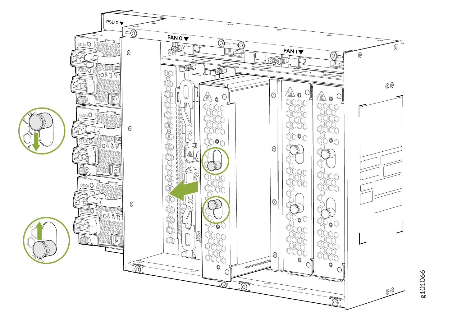
Either remove the failing SIB (see Remove a PTX10004 Switch Interface Board) or remove the cover by grasping each
side of the plate and pulling straight out (see Figure 3).
Figure 3: Remove a SIB Cover on a PTX10004
-
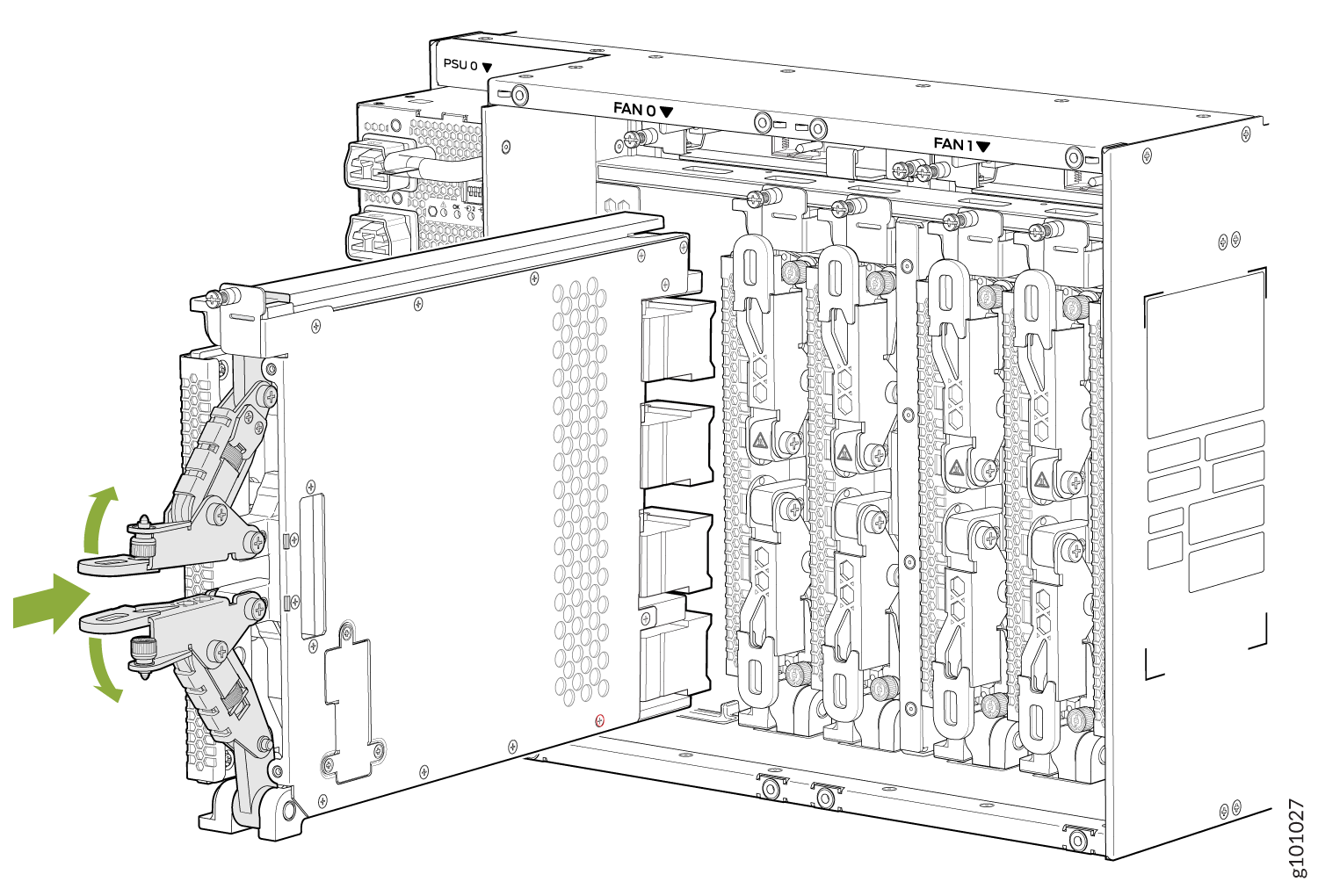
Grasp the two ejector handles and fold them inward until
they latch to seat the SIB (see Figure 4).
Figure 4: Install a PTX10004 Switch Interface Board
Remove a PTX10004 Switch Interface Board
A PTX10004 router has up to six Switch Interface Boards (SIBs) that are located in the middle of the chassis behind the fan trays. SIB 0 through SIB 2 are located behind the left fan tray and SIB 3 through SIB 5 are located behind the right fan tray. You must remove the appropriate fan tray to access the failing SIB. See Remove a PTX10004 Fan Tray.
Ensure you have the following equipment on hand before replacing a SIB:
-
Antistatic bag or antistatic mat
-
Electrostatic discharge (ESD) grounding strap
-
Phillips (+) number 2 screwdriver (optional)
To remove a SIB:
-
Wrap and fasten one end of the ESD grounding strap around
your bare wrist and connect the other end of the strap to an ESD points
on the chassis. There is an ESD point located next to the protective
earthing terminal and below the bottom power supply on the rear of
the PTX10004, (see Figure 5).
Figure 5: ESD Point on the Rear of the PTX10004
1—
ESD point
-
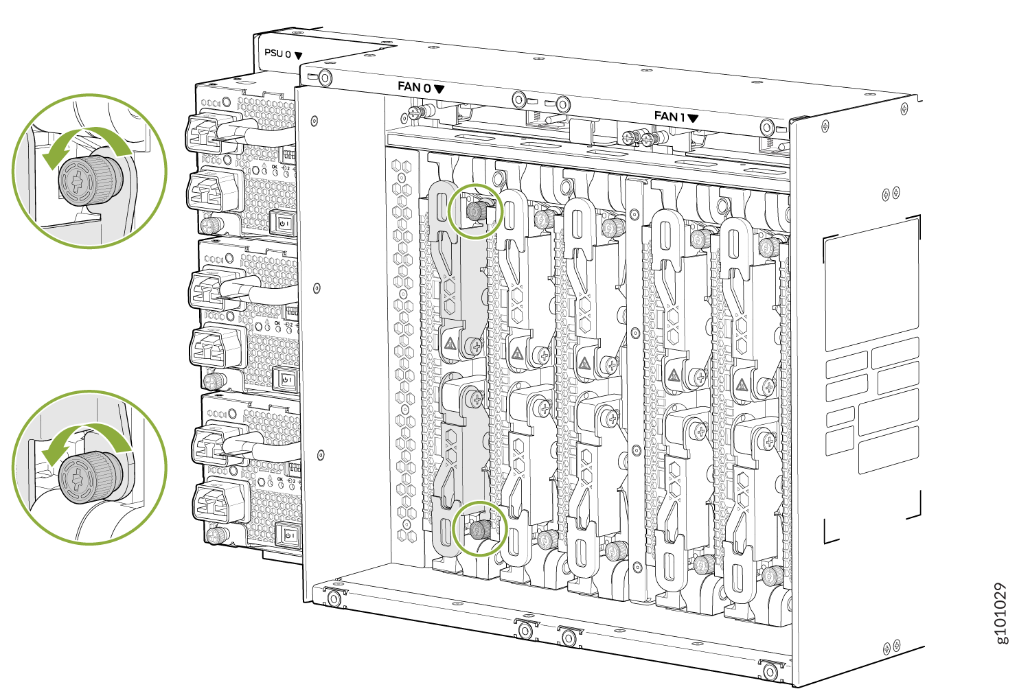
Loosen the captive screws at the top and bottom of the
SIB using your thumb and forefinger or a Phillips screwdriver. See Figure 6.
Figure 6: Loosen the Captive Screws on the SIB
-
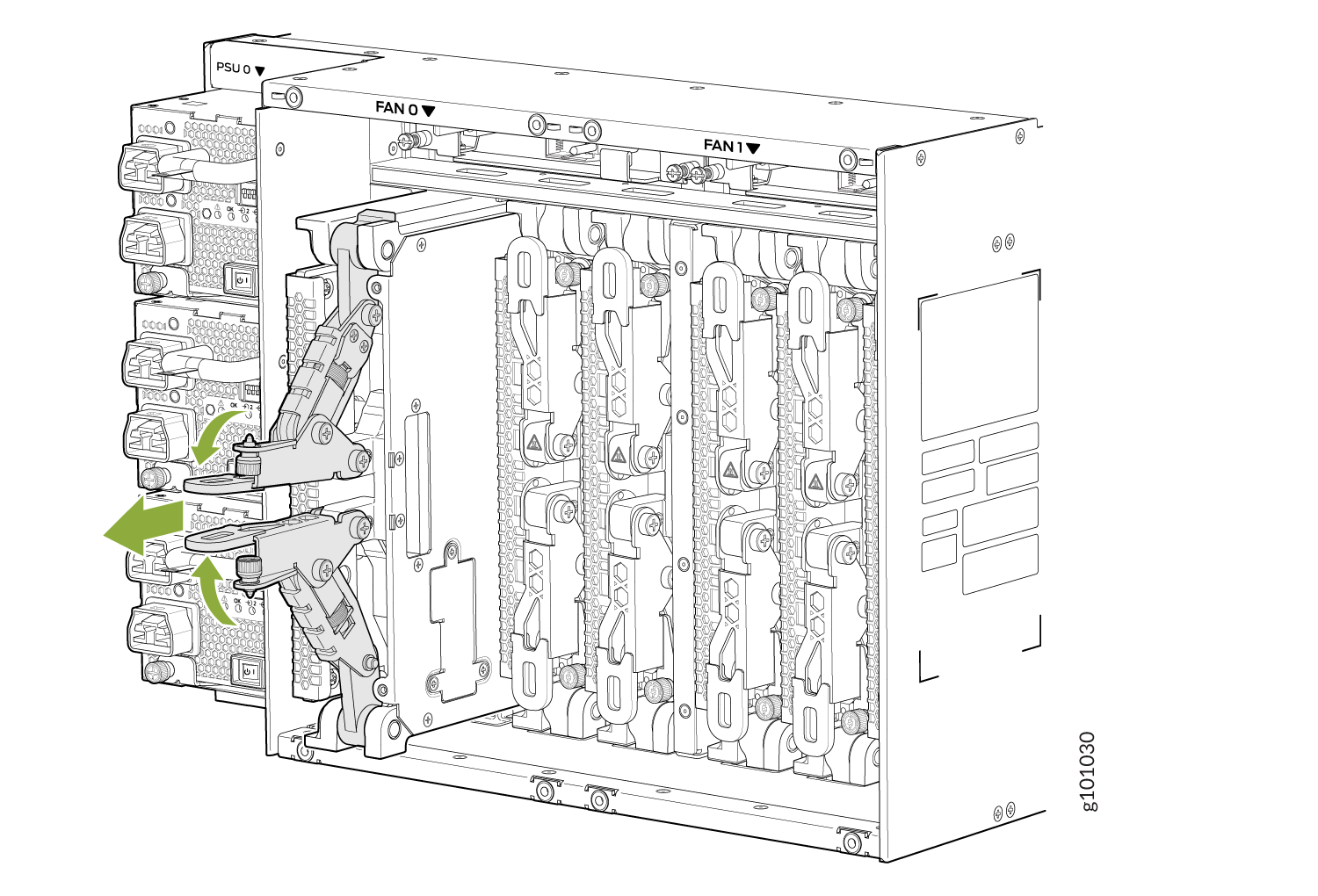
Grasp both ejector handles and bring them together. The
SIB slides about a quarter of the way out of the slot. See Figure 7.
Figure 7: Join the Ejector Handles
-
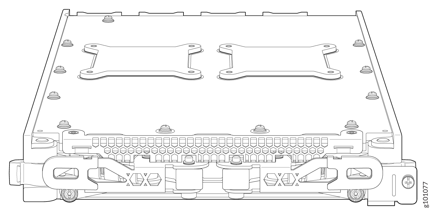
Support the SIB as you rotate the SIB 90 degrees and place
it on the antistatic mat with the printed circuit board (PCB) facing
upward. Be careful not to bump or handle the SIB by the connectors.
If you don’t have an antistatic mat, have another person help
you slide the antistatic bag over the SIB before you place it on a
stable surface. See Figure 8.
CAUTION:
Do not stack hardware components on top of one another after you remove them. Place each component on an antistatic mat resting on a stable, flat surface.
Figure 8: Extracted SIB