Help us improve your experience.

Let us know what you think.

Do you have time for a two-minute survey?


Unpacking and Mounting the PTX10003

Unpacking the PTX10003

The PTX10003 chassis is a rigid sheet-metal structure that houses the hardware components. The PTX10003 is shipped in a cardboard carton, secured with foam packing material. The carton also contains an accessory kit.

CAUTION:

PTX10003 routers are maximally protected inside the shipping carton. Do not unpack the PTX10003 until you are ready to begin installation.

To unpack a PTX10003:

  1. Move the shipping carton to a staging area as close to the installation site as possible, but where you have enough room to remove the system components.
  2. Position the carton so that the arrows point upward.
  3. Open the top flaps on the shipping carton.
  4. Remove the accessory kit.
  5. Pull out the packing material holding the PTX10003 in place.
  6. Verify the following components are in the box:

    For the PTX10003-160C:

    • Chassis with five fan modules and four power supplies installed

    • Two side-mounting blades attached to each side of the chassis

    • Two side-mounting rails attached to each side of the chassis

    • Four power cords with plugs for that are appropriate for your geographical location

    • RJ-45 cable and RJ-45 to DB-9 serial port adapter

    • Accessory kit containing:

      • DC power cable lug (for DC installations)

      • Four M4 x 8 mm flat head screws

      • Four M5 x 10 mm pan head screws

      • End User License Agreement

      • One 2.1 m DB-9-RJ to RJ-45 serial port adapter, straight through cable

      • ESD wrist strap with cable

      • Cable management assembly

      • Road Map card

    For the PTX10003-80C:

    • Chassis with three fan modules and two power supplies installed

    • Two side-mounting blades attached to each side of the chassis

    • Two side-mounting rails attached to the side-mounting blades

    • Two power cords with plugs for that are appropriate for your geographical location

    • RJ-45 cable and RJ-45 to DB-9 serial port adapter

    • Accessory kit containing:

      • DC power cable lug (for DC installations)

      • Four M4 x 8 mm flat head screws

      • Four M5 x 10 mm pan head screws

      • End User License Agreement

      • One DB-9-RJ to RJ-45 serial port adapter, straight through cable

      • ESD wrist strap with cable

      • Cable management assembly

      • Road Map card

  7. Save the shipping carton and packing materials in case you need to move or ship the chassis later.

Mounting the PTX10003 in a Rack

The mounting rails and mounting blades are preattached to the PTX10003. To mount the chassis in a 19-in (48.26 cm) four-post rack, you simply remove one screw to release the sliding rail and then attach the mounting blades to the rack. The sliding mounting rails enable the PTX10003 to be mounted flush with the rack and still be adjustable for racks with different depths. The minimum distance the front and rear rack rails can be spaced apart is 26 in. (66.04 cm) front to back. The maximum distance the front and rear rack rails can be spaced apart is 36 in. (91.4 cm) front to back.

Before You Begin Mounting the PTX10003

  1. Ensure that you understand how to prevent electrostatic discharge (ESD) damage. See Prevention of Electrostatic Discharge Damage.
  2. Verify that the site meets the requirements described in PTX10003 Site Preparation Checklist.
  3. Place the rack in its permanent location, allowing adequate clearance for airflow and maintenance, and secure it to the building structure.
  4. Read General Safety Guidelines and Warnings and PTX10003 Installation Safety Guidelines.
    CAUTION:

    If you are mounting multiple units in the rack, mount the heaviest unit at the bottom and mount the others from bottom to top in order of decreasing weight. The PTX10003-160C weighs approximately 110 lb (50 kg) fully loaded and the PTX10003-80C weighs approximately 88 lb (40 kg) fully loaded. Installing the router in a rack requires either a mechanical lift or two people to lift the device and another person to secure it to the rack.

  5. Decide whether to place the field-replaceable unit (FRU) end or the port end of the PTX10003 at the front of the rack. Position the device in such a manner that the AIR OUT labels on the handle are next to the hot aisle.
  6. Remove the PTX10003 from the shipping carton (see Unpacking the PTX10003).
  7. Ensure that you have the following parts and tools available to mount the PTX10003 in a rack.
    Note:

    Either a mechanical lift or two persons to lift the PTX10003 into place. An additional person is needed for securing the router to the rack.

    • ESD grounding strap (provided).

    • Four power cords (PTX10003-160C) or two power cords (PTX10003-80C) with plugs appropriate to your geographical location (provided).

    • RJ-45 cable and RJ-45 to DB-9 serial port adapter (provided).

    • Management host, such as a PC laptop, with a serial port (not provided).

    • Screwdriver appropriate for the rack-mounting screws (not provided).

    • Grounding cable kit with bracket, lug, and three nuts with integrated washers.

Warning:

PTX10003 routers must be supported at all four corners.

CAUTION:

PTX10003 routers require at least three people for installation, two people to lift the device into place and another person to attach the device to the rack. You can remove the power supplies and fan modules to minimize the weight before attempting to install the PTX10003. See Remove the AC/HVDC Power Supply from the PTX10003 and Removing a Fan Module from the PTX10003. For overhead installation—for example, if you are installing the PTX10003 above 60 in. (152.4 cm) from the floor—we recommend that you use a mechanical lift.

Mounting the PTX10003

  1. Wrap and fasten one end of the ESD wrist strap around your bare wrist, and connect the other end of the strap to the ESD point on the device.
  2. Decide whether to place the field-replaceable unit end or the port end of the PTX10003 at the front of the rack. Position the PTX10003 in such a manner that the AIR OUT label on the handle is next to the hot aisle.
  3. Using a Phillips screwdriver, remove the screw on each side of the chassis that holds the mounting rails to the chassis. (see Figure 1 and Figure 2).
  4. Slide the mounting rail out of the mounting blades.
    Figure 1: Removing the Slide Rail Screw (PTX10003-160C)Removing the Slide Rail Screw (PTX10003-160C)
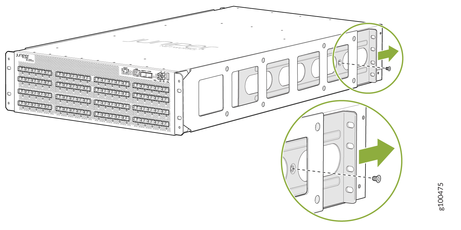
    Figure 2: Removing the Slide Rail Screw (PTX10003-80C)Removing the Slide Rail Screw (PTX10003-80C)
  5. Perform one of the following steps:
    • Use a mechanical lift to position the PTX10003 in the rack so that the front brackets on the front mounting rails are aligned with the rack holes.

    • Have two people grasp both sides of the PTX10003, lift it, and position it in the rack so that the front brackets on the front-mounting rails are aligned with the rack holes.

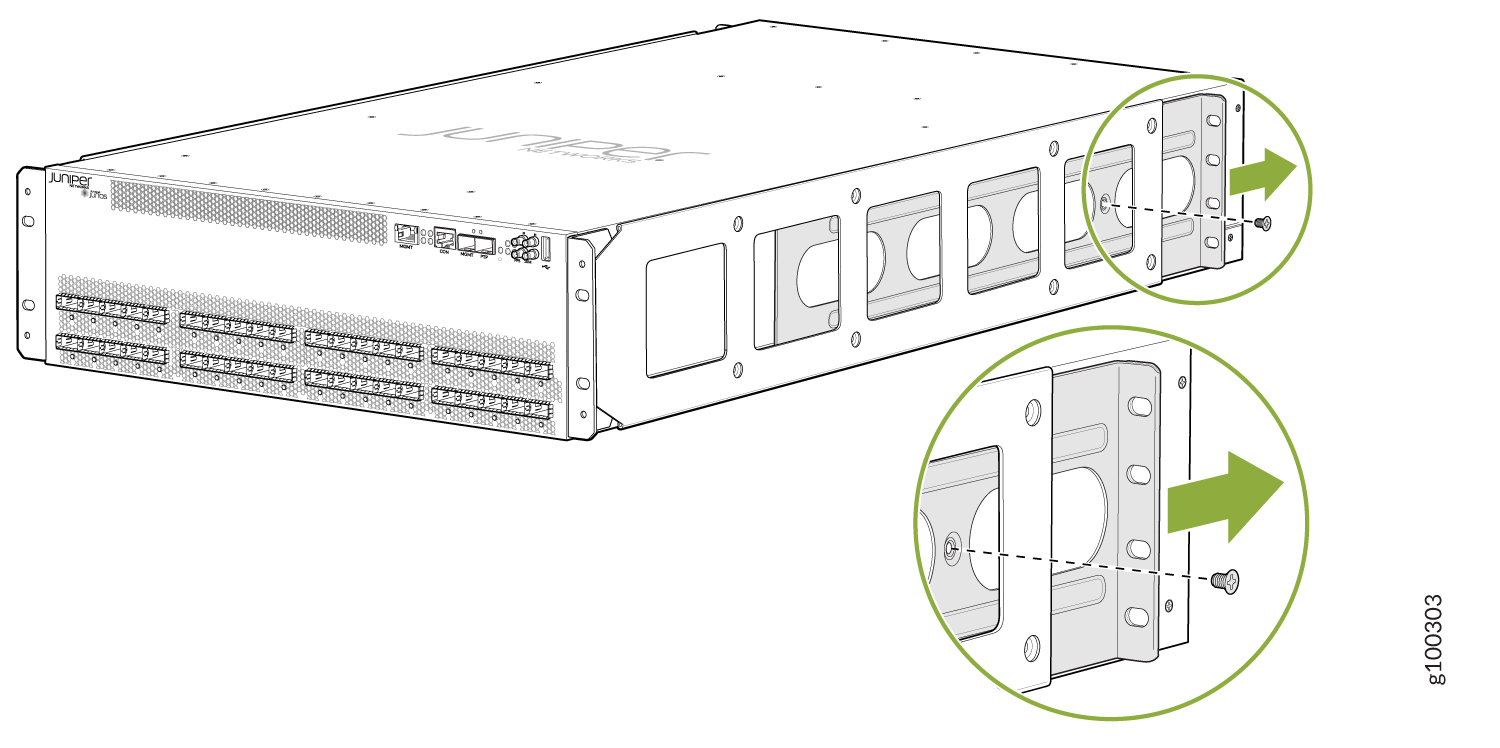
  6. Continue to support the PTX10003 while sliding the rear mounting blades into the channel of the side-mounting rails. See Figure 3 and Figure 4.
    Figure 3: Securing the Side Rails to the PTX10003-160CSecuring the Side Rails to the PTX10003-160C
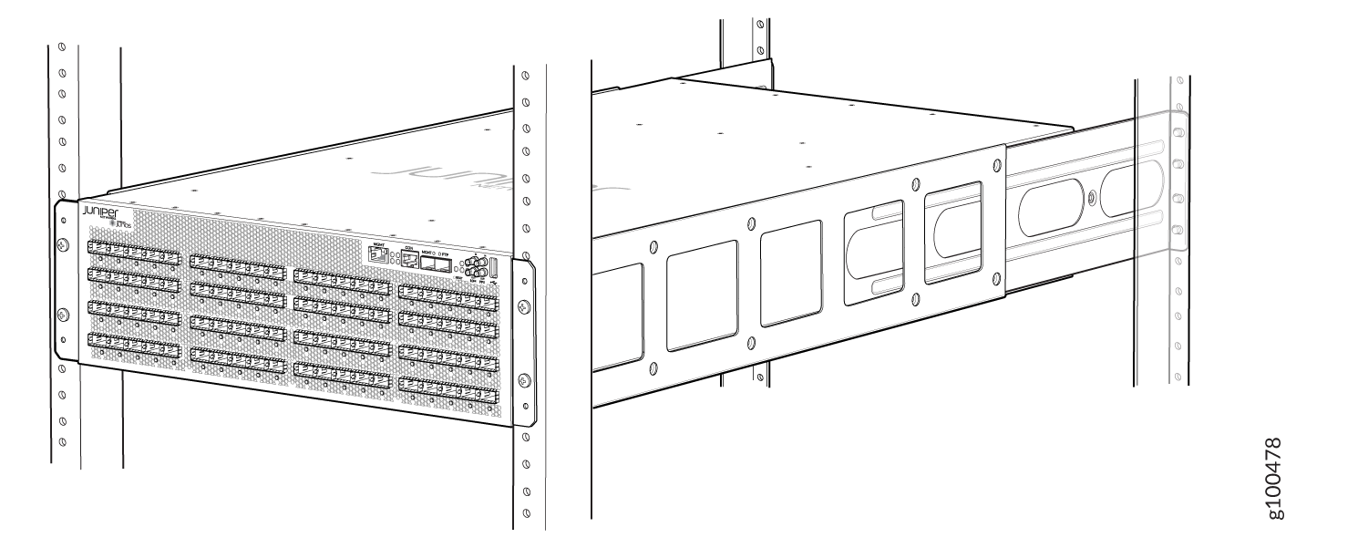
    Figure 4: Securing the Side Rails to the PTX10003-80C ChassisSecuring the Side Rails to the PTX10003-80C Chassis
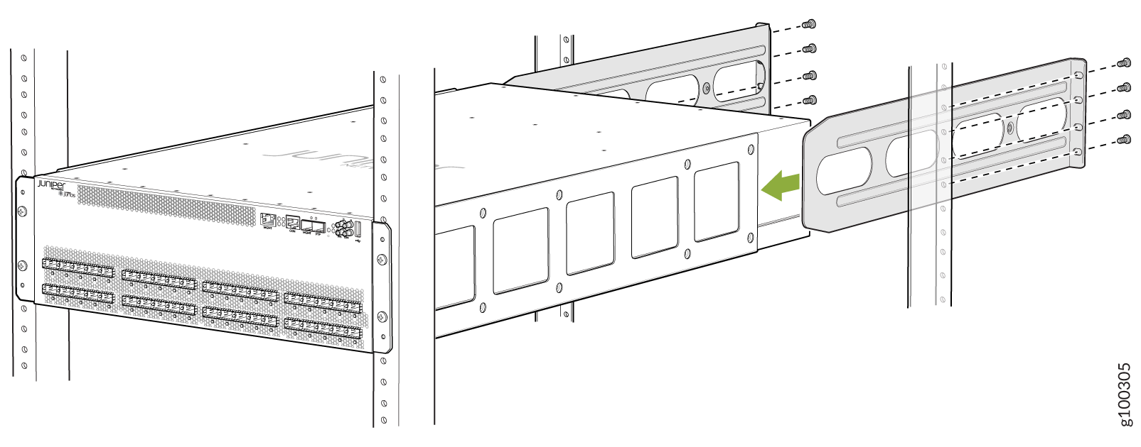
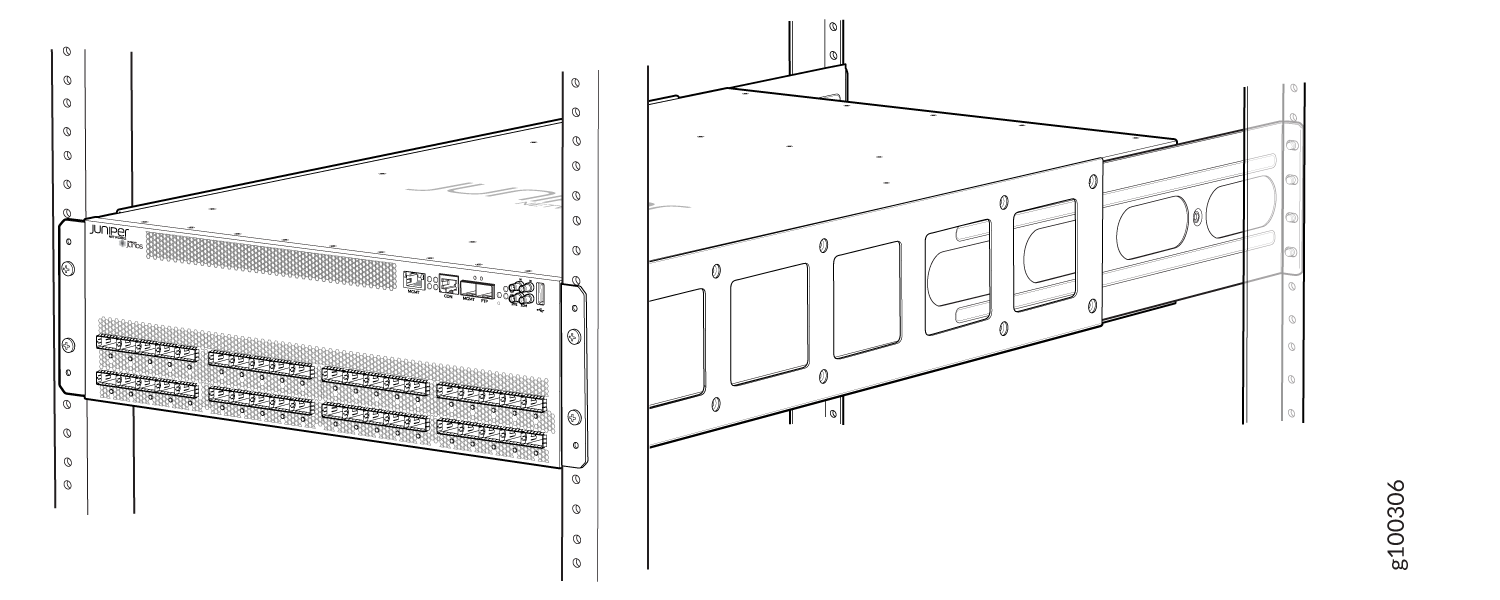
  7. Ensure that the PTX10003 chassis is level by verifying that all the screws on the front of the rack are aligned with the screws at the back of the rack. See Figure 5 and Figure 6.
    Figure 5: PTX10003 Secured in Rack (PTX10003-160C)PTX10003 Secured in Rack (PTX10003-160C)
    Figure 6: PTX10003 Secured in Rack (PTX10003-80C)PTX10003 Secured in Rack (PTX10003-80C)
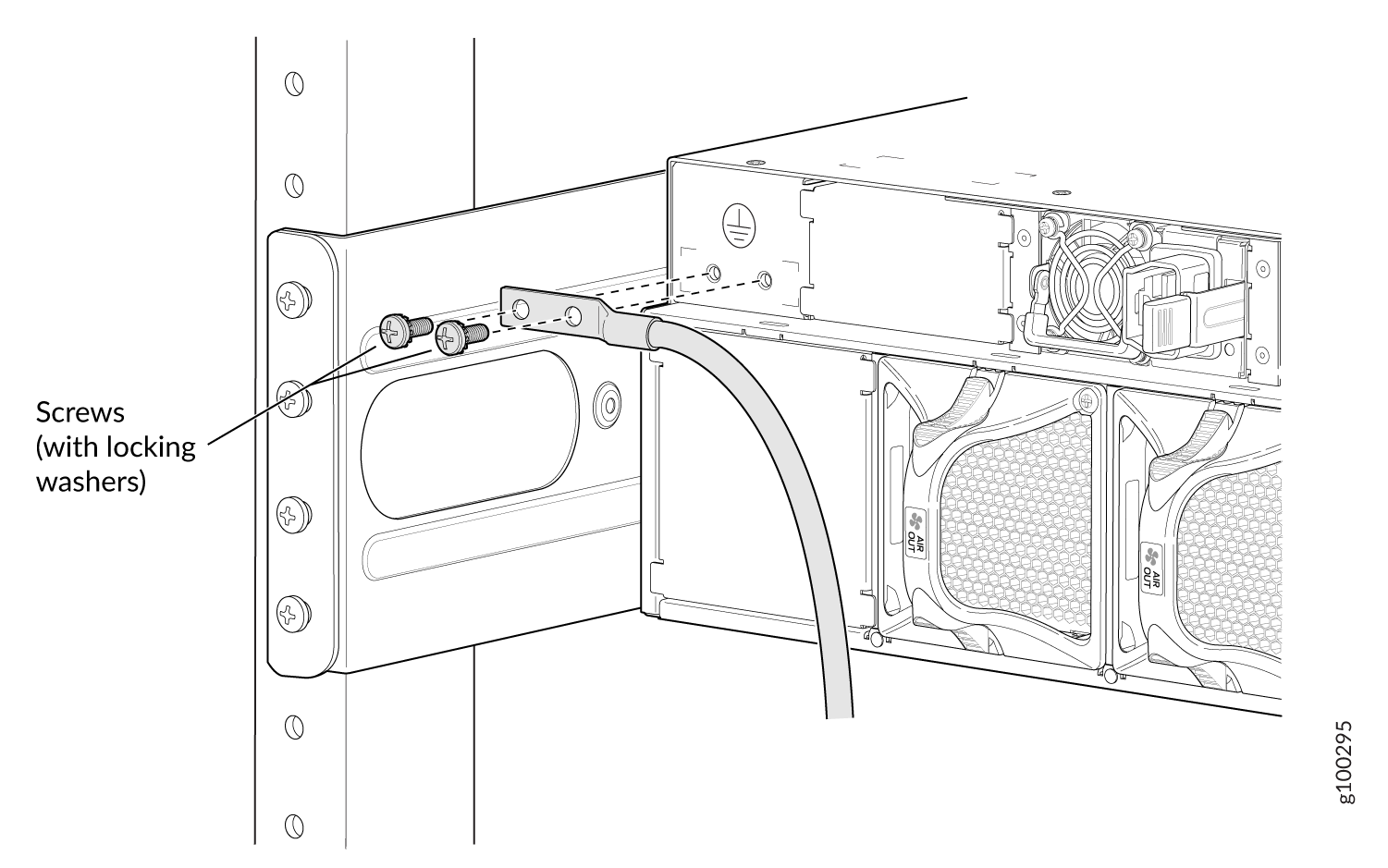
  8. Attach one end of a grounding cable to earth ground and attach the other end to the chassis grounding point. Figure 7 and Figure 8 show the location of the chassis grounding point.
    Figure 7: Chassis Grounding Point (PTX10003-160C)Chassis Grounding Point (PTX10003-160C)
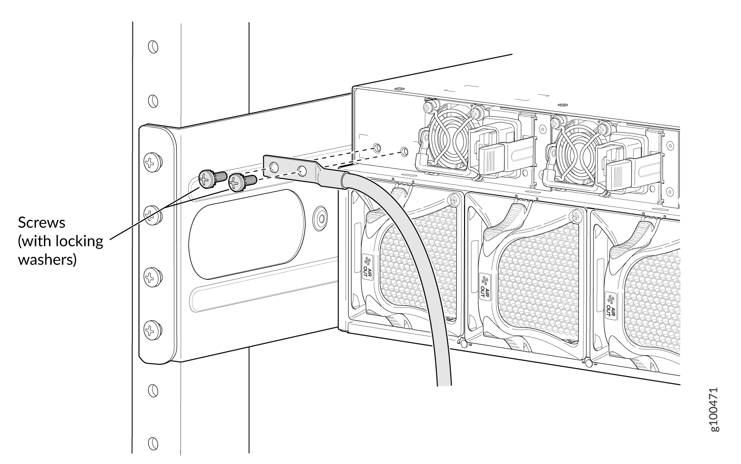
    Figure 8: Chassis Grounding Point (PTX10003-80C)Chassis Grounding Point (PTX10003-80C)
  9. If you removed the power supplies and fan modules from the chassis before installation, reinstall them. Refer to Install the AC/HVDC Power Supply in the PTX10003 and Installing a Fan Module in the PTX10003.