Maintaining the PTX10003 Power Supplies
The power supplies in a PTX10003 are hot-removable and hot-insertable field-replaceable units; You can remove and replace them without powering off the PTX10003 or disrupting routing functions.
Do not mix AC/HVDC and DC power supplies in the same chassis.
Replacing an AC/HVDC Power Supply in the PTX10003
Turn off the power source before disconnecting the power cord to prevent damage to the power connector contact.
If you need to replace all the power supplies installed in your PTX10003, you must power off the PTX10003 before removing the power supplies. See Powering Off the PTX10003.
Replace the power supply within one minute of removal to prevent chassis overheating. Before removing the power supply, ensure you have a replacement power supply available.
The AC/HVDC power supply you are installing must use the same airflow direction as the fan trays installed in the router. Labels on the power supply handle indicate the direction of airflow. See PTX10003 Cooling System Description and Airflow.
Before you replace a power supply in a PTX10003, ensure that you have taken the necessary precautions to prevent electrostatic discharge (ESD) damage (see Prevention of Electrostatic Discharge Damage).
Here’s the parts and tools you’ll need to replace a power supply:
-
ESD grounding strap (provided)
-
Antistatic bag or an antistatic mat (not provided)
-
(For a DC power supply) Phillips (+) screwdriver, number 2 (not provided)
Remove the AC/HVDC Power Supply from the PTX10003
-
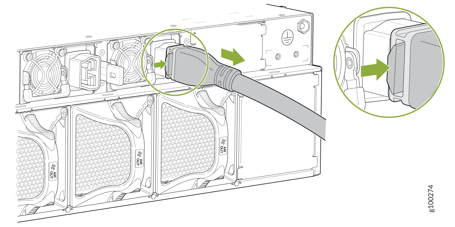
Remove the power cord from the power supply by pressing
in the locking button on the side of the power connector and gently
pulling the connector out of the power supply faceplate. Refer to Figure 1.
Figure 1: Removing the Power Cord from the Power Supply
-
Place one hand under the power supply to support it and
slide it completely out of the chassis. Take care not to touch power
supply components, pins, leads, or solder connections. See Figure 2 and Figure 3.
Figure 2: Removing an AC/HVDC Power Supply from the PTX10003-160C
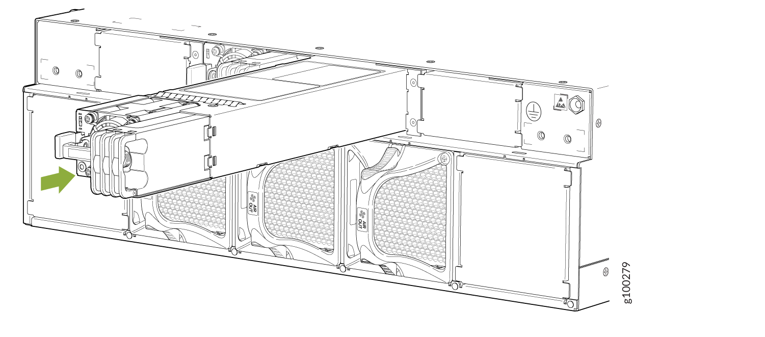
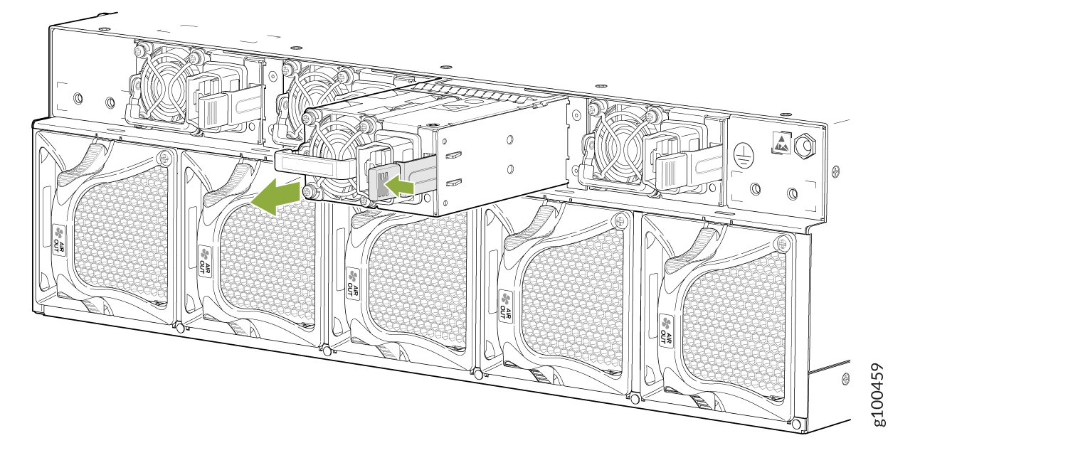 Figure 3: Removing an AC/HDVC Power Supply from the PTX10003-80C
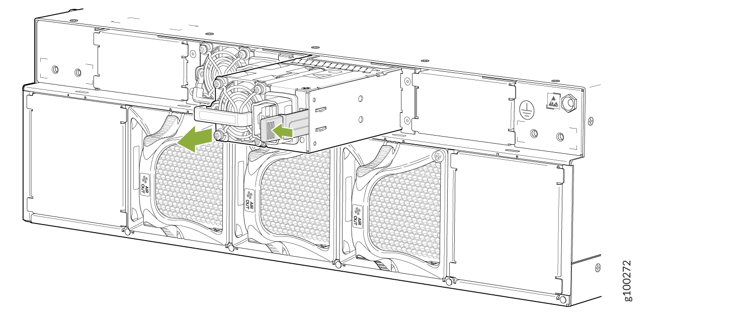
Install the AC/HVDC Power Supply in the PTX10003
Install the power supply within one minute of removal to prevent chassis overheating. Before removing the power supply, ensure you have a replacement power supply available.
- Wrap and fasten one end of the ESD wrist strap around your bare wrist, and connect the other end of the strap to the ESD point on the device.
- If the power supply has protective plastic wrap, peel and remove the plastic wrap from all four sides of the power supply.
- Taking care not to touch power supply components, pins, leads, or solder connections, remove the power supply from its bag.
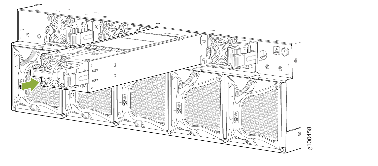
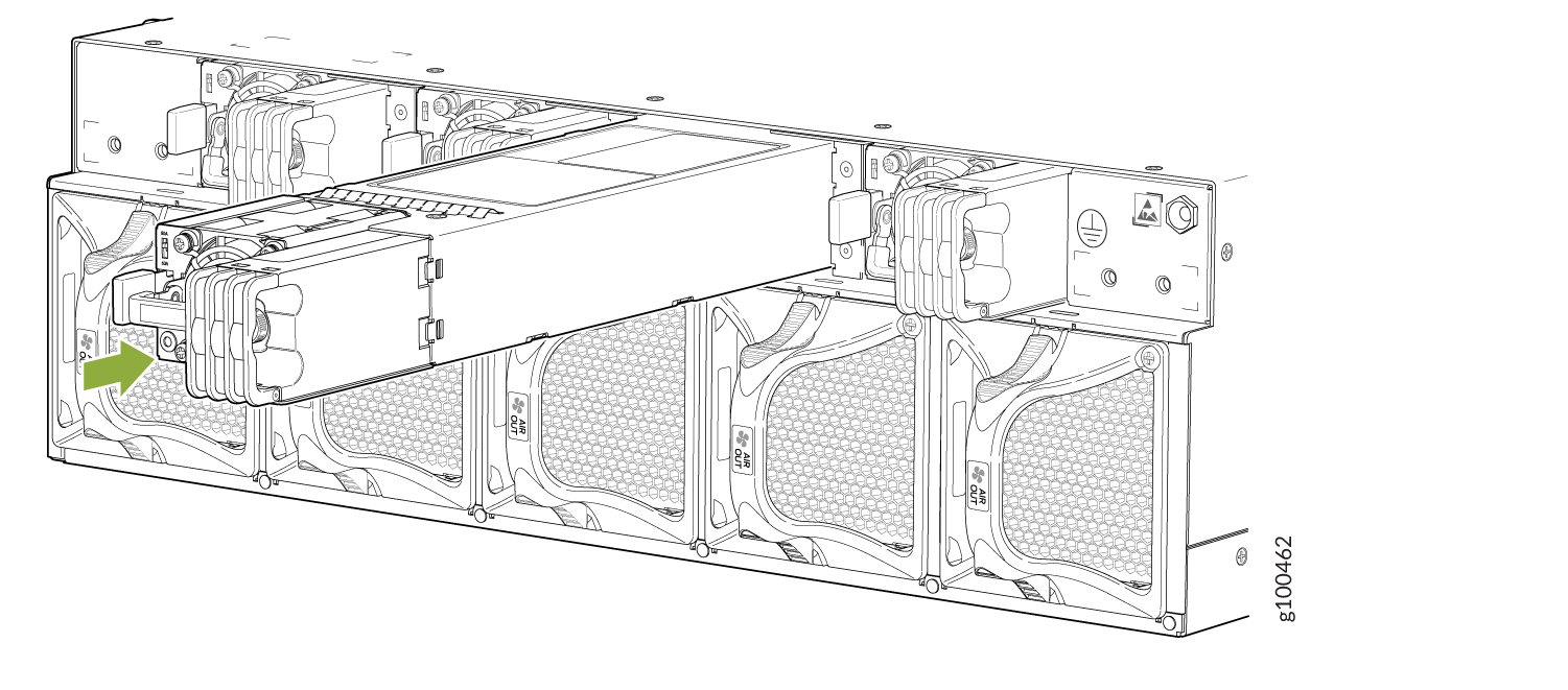
- Using both hands, place the power supply in the power supply slot on the field replaceable units (FRU) panel of the PTX10003 and slide it in until it is fully seated and the ejector lever slides into place. See Figure 4 and Figure 5.
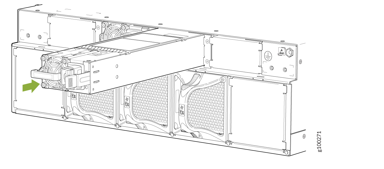
Each power supply must be connected to a dedicated power source outlet.
If you have a Juniper Care service contract, register any addition, change, or upgrade of hardware components at https://www.juniper.net/customers/support/tools/updateinstallbase/ . Failure to do so can result in significant delays if you need replacement parts. This note does not apply if you replace existing components with the same type of component.
Replacing an DC Power Supply in the PTX10003
Turn off the circuit breaker for the DC power source before disconnecting the power cord from the power supply. Unplugging an DC connection while the power supply is powered up may damage the electrical connectors.
If you need to replace all the power supplies installed in your PTX10003, you must power off the PTX10003 before removing the power supplies. See Powering Off the PTX10003.
Replace the power supply within one minute of removal to prevent chassis overheating. Before removing the power supply, ensure you have a replacement power supply available.
The DC power supply you are installing must use the same airflow direction as the fan trays installed in the router. Labels on the power supply handle indicate the direction of airflow. See PTX10003 Cooling System Description and Airflow.
Before you replace a power supply in a PTX10003, ensure that you have taken the necessary precautions to prevent electrostatic discharge (ESD) damage (see Prevention of Electrostatic Discharge Damage).
Remove the DC Power Supply from the PTX10003
-
Place one hand under the power supply to support it and
slide it completely out of the chassis. Take care not to touch power
supply components, pins, leads, or solder connections. See Figure 6and Figure 7.
Figure 6: Removing a DC Power Supply from the PTX10003-160C
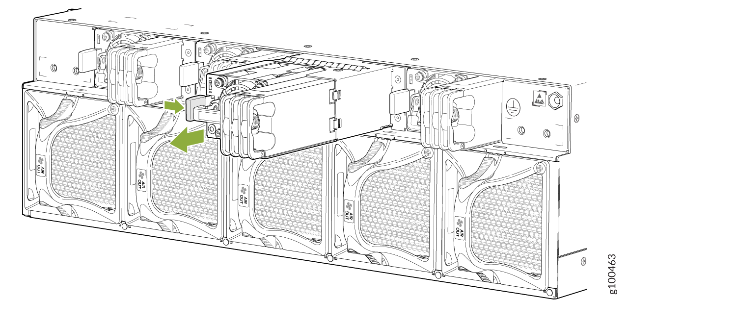 Figure 7: Removing a DC Power Supply from the PTX10003-80C
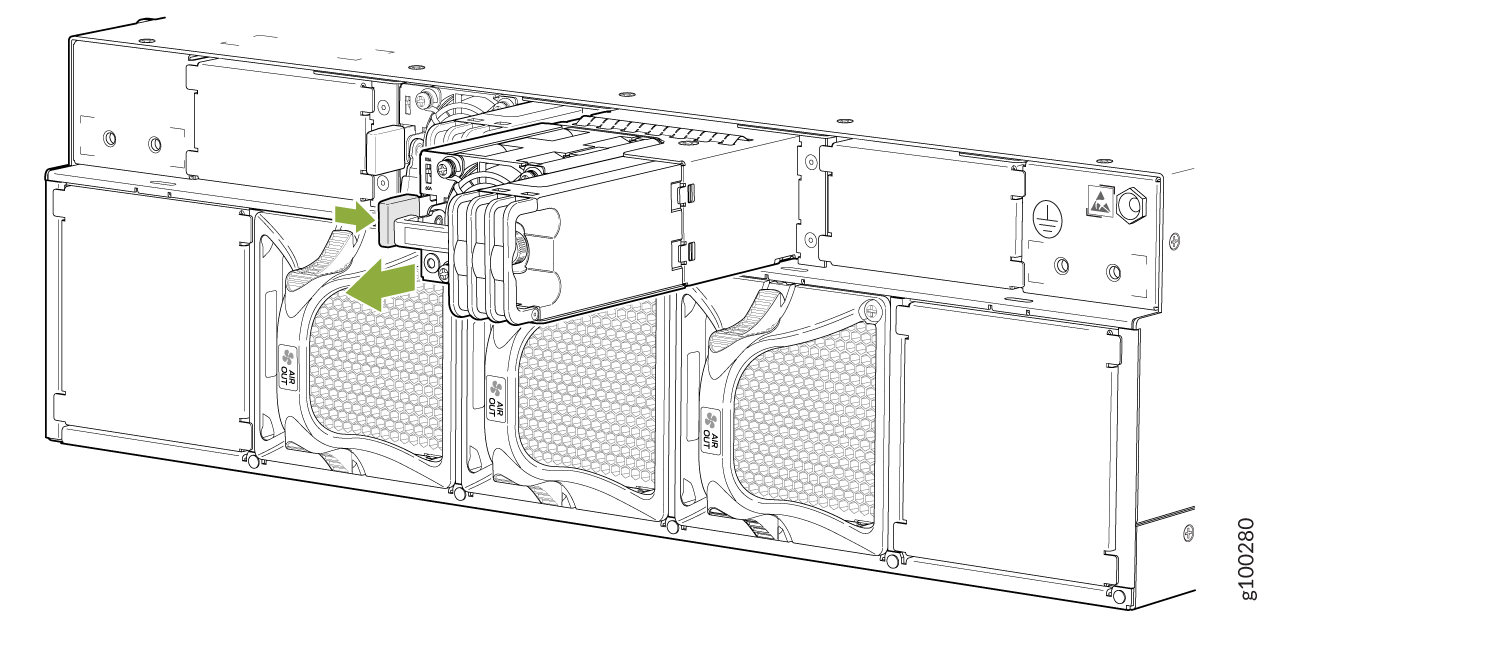
Install the DC Power Supply in the PTX10003
Install the power supply within one minute of removal to prevent chassis overheating. Before removing the power supply, ensure you have a replacement power supply available.
- Wrap and fasten one end of the ESD wrist strap around your bare wrist, and connect the other end of the strap to the ESD point on the device.
- If the power supply has protective plastic wrap, peel and remove the plastic wrap from all four sides of the power supply.
- Taking care not to touch power supply components, pins, leads, or solder connections, remove the power supply from its bag.
- To prevent damage to the equipment caused by static discharge, attach an ESD grounding strap to your bare wrist, and connect the strap to one of the ESD points on the chassis.
- Taking care not to touch power supply components, pins, leads, or solder connections, remove the power supply from its bag.
- Using both hands, place the power supply in the power supply slot on the field replaceable units (FRU) panel of the PTX10003 and slide it in until it is fully seated and the locking lever slides into place. See Figure 8 and Figure 9.
Each power supply must be connected to a dedicated power source outlet.
If you have a Juniper Care service contract, register any addition, change, or upgrade of hardware components at https://www.juniper.net/customers/support/tools/updateinstallbase/ . Failure to do so can result in significant delays if you need replacement parts. This note does not apply if you replace existing components with the same type of component.