ON THIS PAGE
Maintain MX304 Interface Modules
Maintain LMICs
Purpose
The router can have up to three LMICs mounted horizontally in the card cage at the front of the chassis. For optimum router performance, verify the condition of the LMICs.
Action
On a regular basis:
-
Check the OK/FAIL LED on the LMIC. If the LMIC detects a failure, the LMIC sends an alarm message to the Routing Engine.
-
Issue the
show chassis fpcCLI command to check the status of installed LMICs. As shown in the sample output, the value Online in the column labeled State indicates that the LMIC is functioning normally:user@host> show chassis fpc Temp CPU Utilization (%) CPU Utilization (%) Memory Utilization (%) Slot State (C) Total Interrupt 1min 5min 15min DRAM (MB) Heap Buffer 0 Online 36 6 0 5 5 5 32768 19 0For more detailed output, add the detail option. The following example does not specify a slot number, which is optional:
user@host> show chassis fpc detail
Slot 0 information:
  State                               Online
  Total CPU DRAM                 32768 MB
  Total HBM                      65536 MB
  FIPS Capable                        True
  Temperature                      42 degrees C / 107 degrees F
  Start time                          2022-05-30 08:00:24 IST
  Uptime                              13 minutes, 13 seconds
  Max MPC base power consumption  1105 Watts
  Max MIC0 power consumption        95 Watts
  Max MIC1 power consumption        95 Watts
  Max MIC2 power consumption        95 Watts
  Max MPC total power consumption 1390 Watts

PFE Information:

  PFE  Power ON/OFF  Bandwidth         SLC
  0    ON            800G
  1    ON            800G
  2    ON            800G
  3    ON            800G
  4    ON            800G
  5    ON            800G
-
On Junos OS 24.4R1 or later, issue the
show chassis fpc mic-statusCLI command to check the status of the LMICs whenever you take the LMIC offline or online to ensure that the operation has completed before performing any further actions on the LMIC.user@host> show chassis fpc mic-status Slot 0 Online FPC-BUILTIN MIC 0 Offline MRATE LMIC 16x100G/4x400G MIC 1 Online MRATE LMIC 16x100G/4x400G PIC 1 Online MRATE LMIC 16x100G/4x400G MIC 2 Online MRATE LMIC 16x100G/4x400G PIC 2 Online MRATE LMIC 16x100G/4x400G
-
Issue the
show chassis fpc pic-statusCLI command.user@host> show chassis fpc pic-status Slot 0 Online FPC-BUILTIN PIC 0 Offline MRATE LMIC 16x100G/4x400G PIC 1 Online MRATE LMIC 16x100G/4x400G PIC 2 Online MRATE LMIC 16x100G/4x400G
Note: For LMIC-related operations such as LMIC insertion or removal on Junos OS 24.4R1 and later, use theshow chassis fpc mic-statuscommand to check the status of the LMICs.
For further description of the output from the command, see the CLI Explorer.
Replace an MX304 LMIC
On the MX304 router, all the LMICs are removable. You can have up to three LMICs in the router.
The LMICs are located on the front side of the router. A typical LMIC weighs around 6.17 lb (2.8 kg).
On Junos OS releases earlier than 24.4R1, you must take the FPC offline to remove or insert an LMIC. All LMICs lose service during this process.
Starting in Junos OS 24.4R1 or later, the LMICs function as hot-removable and hot-insertable FRUs. You can use the CLI to take individual LMICs offline or bring them back online, allowing you to gracefully remove or insert them without impacting the other operational LMICs. While an LMIC is taken offline or brought online:
-
All subscriber sessions on the Packet Forwarding Engine are terminated, and their flows are deleted, except when an alternate Packet Forwarding Engine provides redundancy. DHCP subscriber sessions remain connected even when the Packet Forwarding Engine is taken offline. When the LMIC comes back online, the pre-existing DHCP subscriber functions resume. Subscribers and flows are retained when an alternate Packet Forwarding Engine provides redundancy. See Subscriber Management Redundancy for PFE During Graceful OIR for more information.
-
Port mirroring reacts to the hot removal and hot insertion of LMICs in the following ways:
-
If the Packet Forwarding Engine hosting the output mirroring destination interface (MDI) goes offline, traffic from the input mirroring interface is not mirrored. Mirroring resumes when the Packet Forwarding Engine hosting the MDI comes back online.
-
In a port-mirroring next-hop-group or next-hop-subgroup scenario, if a Packet Forwarding Engine hosting MDIs goes offline, the MDIs associated with the offline Packet Forwarding Engine are pruned from the member list. Those associated MDIs are added back to the member list when the Packet Forwarding Engine hosting the MDIs comes back online.
-
If the Packet Forwarding Engine hosting the mirroring interface goes offline, traffic entering, leaving, and mirrored at the interface stops. Ingress and egress mainline traffic and mirroring resume when the Packet Forwarding Engine hosting the mirroring interface comes back online.
-
-
Monitoring services such as inline active flow monitoring, inline monitoring services, video monitoring, Routing-Engine-based sampling, and FlowTapLite gracefully stop and restart when you take the LMIC offline and bring it back online.
Use the instructions in the following sections to remove and insert an LMIC on the MX304 router:
Remove an MX304 LMIC
To remove an LMIC (see Figure 1):
-
If you're not reinstalling an LMIC into the emptied LMIC slot within a
short time, install a blank LMIC panel over the slot to maintain proper
airflow in the chassis.
Figure 1: Remove an MX304 LMIC
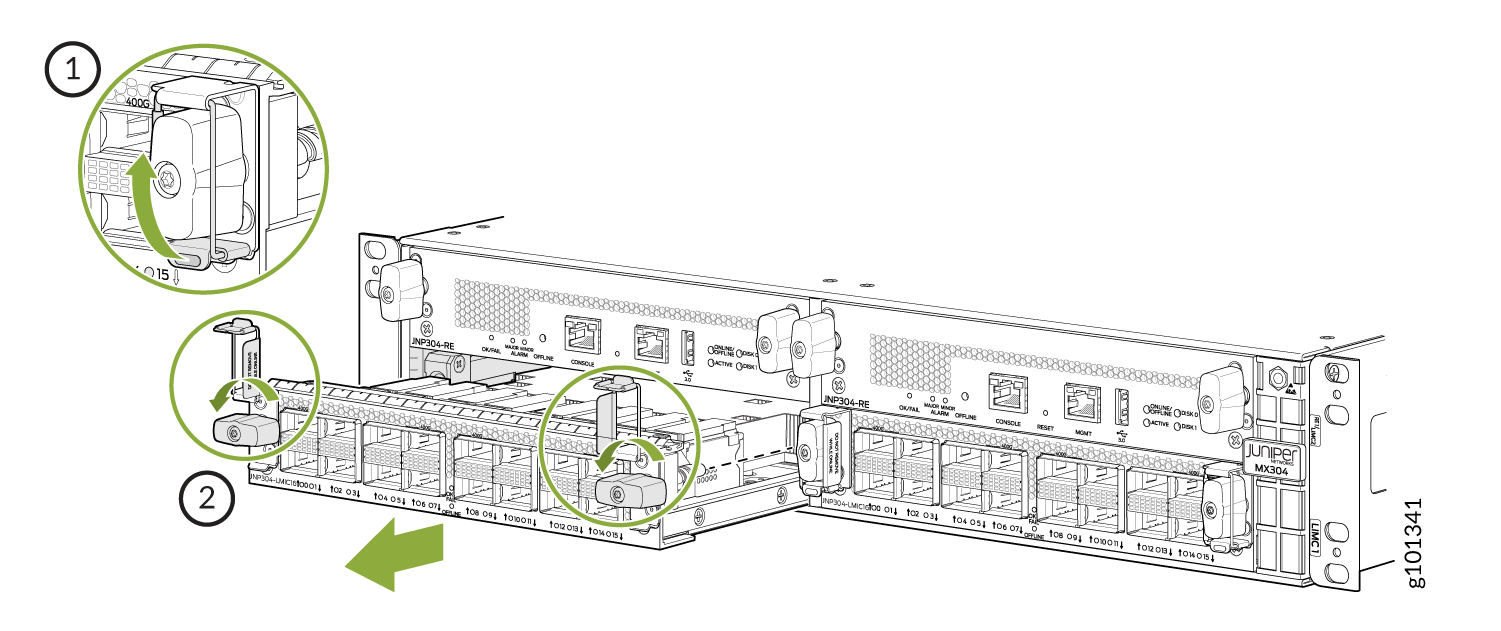 1—
1—Hold the knob lock and lift it up.
2—Turn handles anti-clockwise and remove the LMIC.
Maintain Cables That Connect to LMICs
Purpose
For optimum router performance, verify the condition of the cables that connect to the LMICs.
Action
On a regular basis:
Use the cable management brackets to support cables and prevent cables from coming unplugged or developing stress points.
Place excess cable out of the way in the cable management brackets. Do not allow fastened loops of cable to dangle from the connector or cable management brackets, because this stresses the cable at the fastening point. Putting fasteners on the loops helps to maintain their shape.
Keep the cable connections clean and free of dust and other particles, which can cause drops in the received power level. Always inspect cables and clean them if necessary before connecting an interface.
Label both ends of the cables to identify them.
The following guidelines apply specifically to fiber-optic cables:
When you unplug a fiber-optic cable, always place a rubber safety plug over the transceiver on the faceplate and on the end of the cable.
Anchor fiber-optic cables to avoid stress on the connectors. Be sure to secure fiber-optic cables so that they do not support their own weight as they hang to the floor. Never let fiber-optic cable hang free from the connector.
Avoid bending fiber-optic cable beyond its bend radius. An arc smaller than a few inches can damage the cable and cause problems that are difficult to diagnose.
Frequent plugging and unplugging of fiber-optic cable into and out of optical instruments can cause damage to the instruments and is expensive to repair. Instead, attach a short fiber extension to the optical equipment. Any wear and tear due to frequent plugging and unplugging is then absorbed by the short fiber extension, which is easy and inexpensive to replace.
Keep fiber-optic cable connections clean. Small microdeposits of oil and dust in the canal of the transceiver or cable connector could cause loss of light, reducing signal power and possibly causing intermittent problems with the optical connection.
To clean the transceivers, use an appropriate fiber-cleaning device, such as RIFOCS Fiber Optic Adaptor Cleaning Wands (part number 946). Follow the directions for the cleaning kit you use.
After you clean an optical transceiver, make sure that the connector tip of the fiber-optic cable is clean. Use only an approved alcohol-free fiber-optic cable cleaning kit, such as the Opptex Cletop-S Fiber Cleaner. Follow the directions for the cleaning kit you use.
Replace a Cable on an MX304 LMIC
Remove a Cable on an LMIC
Removing and installing cables on an LMIC does not affect router function.
To remove a cable:
Install a Cable on an LMIC
To install a cable:
Replace an SFP, SFP+, or QSFP+ Transceiver
The transceivers for Juniper Networks devices are hot-removable and hot-insertable field-replaceable units (FRUs). You can remove and replace them without powering off the device or disrupting the device functions.
Remove a Transceiver
Before you begin removing a transceiver from a device, ensure that you have taken the necessary precautions for the safe handling of lasers (see Laser and LED Safety Guidelines and Warnings).
Ensure that you have the following parts and tools available:
An antistatic bag or an antistatic mat
Rubber safety caps to cover the transceiver and fiber-optic cable connector
A dust cover to cover the port or a replacement transceiver
After you remove a transceiver or when you change the media-type configuration, wait for 6 seconds for the interface to display the operational commands.
To remove a transceiver:
- By using your fingers, pull open the ejector lever on
the transceiver to unlock the transceiver.CAUTION:
Ensure that you open the ejector handle completely until you hear it click. Doing this prevents damage to the transceiver.
Figure 3 shows how to remove an SFP transceiver. The procedure is the same for SFP+ and QSFP+ transceivers.
Figure 3: Small Form-Factor Pluggable (SFP) Transceiver
After removing a transceiver from the chassis, wait at least 30 seconds before reinserting it or inserting a transceiver into a different slot.
Install a Transceiver
Before you begin to install a transceiver in a device, ensure that you have taken the necessary precautions for safe handling of lasers (see Laser and LED Safety Guidelines and Warnings).
Ensure that you have a rubber safety cap available to cover the transceiver.
After you insert a transceiver or after you change the media-type configuration, wait for 6 seconds for the interface to display operational commands.
We recommend that you use only optical transceivers and optical connectors purchased from Juniper Networks with your Juniper Networks device.
The Juniper Networks Technical Assistance Center (JTAC) provides complete support for Juniper-supplied optical modules and cables. However, JTAC does not provide support for third-party optical modules and cables that are not qualified or supplied by Juniper Networks. If you face a problem running a Juniper device that uses third-party optical modules or cables, JTAC may help you diagnose host-related issues if the observed issue is not, in the opinion of JTAC, related to the use of the third-party optical modules or cables. Your JTAC engineer will likely request that you check the third-party optical module or cable and, if required, replace it with an equivalent Juniper-qualified component.
Use of third-party optical modules with high-power consumption (for example, coherent ZR or ZR+) can potentially cause thermal damage to or reduce the lifespan of the host equipment. Any damage to the host equipment due to the use of third-party optical modules or cables is the users’ responsibility. Juniper Networks will accept no liability for any damage caused due to such use.
To install a transceiver:
- Slide in the transceiver until it is fully seated. If
you are unable to fully insert the transceiver, ensure that the connector
is facing the right way.Figure 4: Install a Transceiver
 1—
1—Ejector lever
Replace a QSFP28 Transceiver
28-Gbps quad small form-factor pluggable (QSFP28) transceivers are hot-insertable and hot-removable. Removing a QSFP28 transceiver does not interrupt router functioning, but the removed QSFP28 transceiver no longer receives or transmits data.
Remove a QSFP28 Transceiver
Before you begin to remove a transceiver from a device, ensure that you have taken the necessary precautions for safe handling of lasers (see Laser and LED Safety Guidelines and Warnings).
Ensure that you have the following parts and tools available:
An antistatic bag or an antistatic mat
Rubber safety caps to cover the transceiver and fiber-optic cable connector
A dust cover to cover the port or a replacement transceiver
The transceivers for Juniper Networks devices are hot-removable and hot-insertable field-replaceable units (FRUs). You can remove and replace them without powering off the device or disrupting the device functions.
After you insert a transceiver or after you change the media-type configuration, wait for 6 seconds for the interface to display operational commands.
We recommend that you use only optical transceivers and optical connectors purchased from Juniper Networks with your Juniper Networks device.
To remove a QSFP28 transceiver (see Figure 5):
- Pull the transceiver’s rubber handle straight back.
The locking pins on the transceiver automatically releases the transceiver.
Figure 5: 28-Gbps Quad Small Form-Factor Pluggable (QSFP28) Transceiver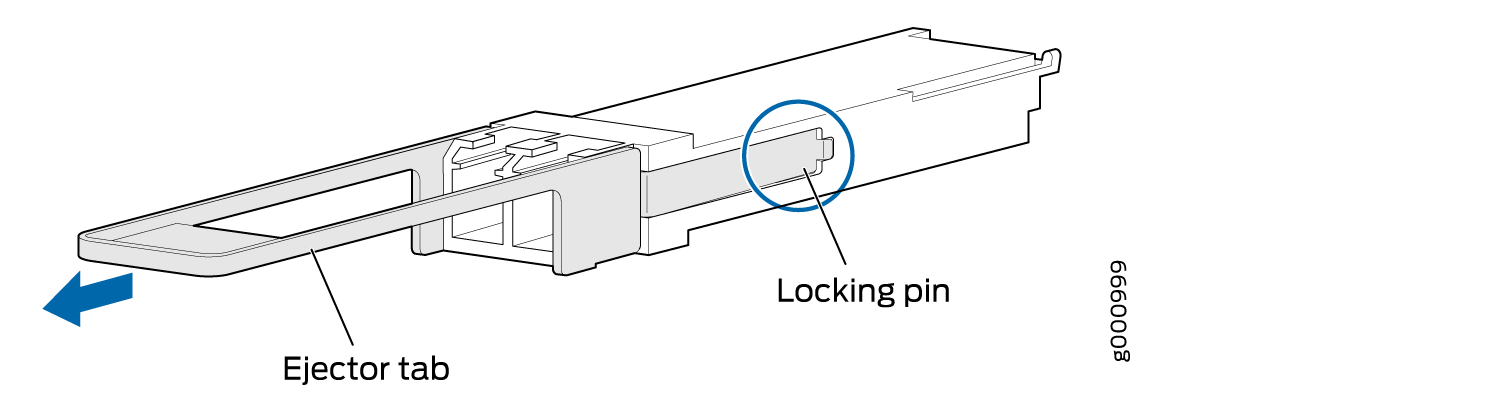
Install a QSFP28 Transceiver
Before you begin to install a transceiver in a device, ensure that you have taken the necessary precautions for safe handling of lasers (see Laser and LED Safety Guidelines and Warnings).
Ensure that you have a rubber safety cap available to cover the transceiver.
The transceivers for Juniper Networks devices are hot-removable and hot-insertable field-replaceable units (FRUs): You can remove and replace them without powering off the device or disrupting the device functions.
After you insert a transceiver or after you change the media-type configuration, wait for 6 seconds for the interface to display operational commands.
We recommend that you use only optical transceivers and optical connectors purchased from Juniper Networks with your Juniper Networks device.
The Juniper Networks Technical Assistance Center (JTAC) provides complete support for Juniper-supplied optical modules and cables. However, JTAC does not provide support for third-party optical modules and cables that are not qualified or supplied by Juniper Networks. If you face a problem running a Juniper device that uses third-party optical modules or cables, JTAC may help you diagnose host-related issues if the observed issue is not, in the opinion of JTAC, related to the use of the third-party optical modules or cables. Your JTAC engineer will likely request that you check the third-party optical module or cable and, if required, replace it with an equivalent Juniper-qualified component.
Use of third-party optical modules with high-power consumption (for example, coherent ZR or ZR+) can potentially cause thermal damage to or reduce the lifespan of the host equipment. Any damage to the host equipment due to the use of third-party optical modules or cables is the users’ responsibility. Juniper Networks will accept no liability for any damage caused due to such use.
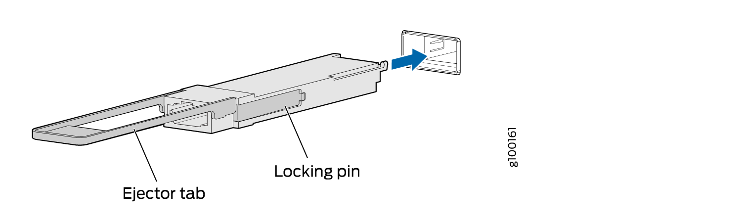
To install a replacement QSFP28 transceiver (see Figure 6):
- Orient the transceiver in front of the port so that the
QSFP28 connector faces the appropriate direction.Figure 6: Install a QSFP28 Transceiver
Replace a QSFP56-DD Transceiver
400-Gbps quad small form-factor pluggable (QSFP56-DD) transceivers are hot-insertable and hot-removable. The transceivers have four optical lanes that operate at 100Gbps PAM4 modulation, providing solutions up to 400 Gbps. They are compliant with the QSFP-DD MSA (DD = Double Density). Removing a QSFP56-DD transceiver does not interrupt router functioning, but the removed QSFP56-DD transceiver no longer receives or transmits data.
Remove a QSFP56-DD Transceiver
Before you begin to remove a transceiver from a device, ensure that you have taken the necessary precautions for safe handling of lasers (see Laser and LED Safety Guidelines and Warnings).
Ensure that you have the following parts and tools available:
-
An antistatic bag or an antistatic mat
-
Rubber safety caps to cover the transceiver and fiber-optic cable connector
-
A dust cover to cover the port or a replacement transceiver
The transceivers for Juniper Networks devices are hot-removable and hot-insertable field-replaceable units (FRUs). You can remove and replace them without powering off the device or disrupting the device functions.
After you insert a transceiver or after you change the media-type configuration, wait for 6 seconds for the interface to display operational commands.
We recommend that you use only optical transceivers and optical connectors purchased from Juniper Networks with your Juniper Networks device.
To remove a QSFP56-DD transceiver (see Figure 7 ):
-
Pull the transceiver’s rubber handle straight back.
The locking pins on the transceiver automatically releases the transceiver.
Figure 7: 400-Gbps Quad Small Form-Factor Pluggable (QSFP56-DD) Transceiver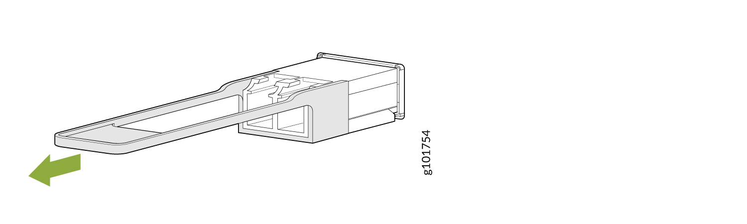
Install a QSFP56-DD Transceiver
Before you begin to install a transceiver in a device, ensure that you have taken the necessary precautions for safe handling of lasers (see Laser and LED Safety Guidelines and Warnings).
Ensure that you have a rubber safety cap available to cover the transceiver.
The transceivers for Juniper Networks devices are hot-removable and hot-insertable field-replaceable units (FRUs): You can remove and replace them without powering off the device or disrupting the device functions.
After you insert a transceiver or after you change the media-type configuration, wait for 6 seconds for the interface to display operational commands.
We recommend that you use only optical transceivers and optical connectors purchased from Juniper Networks with your Juniper Networks device.
The Juniper Networks Technical Assistance Center (JTAC) provides complete support for Juniper-supplied optical modules and cables. However, JTAC does not provide support for third-party optical modules and cables that are not qualified or supplied by Juniper Networks. If you face a problem running a Juniper device that uses third-party optical modules or cables, JTAC may help you diagnose host-related issues if the observed issue is not, in the opinion of JTAC, related to the use of the third-party optical modules or cables. Your JTAC engineer will likely request that you check the third-party optical module or cable and, if required, replace it with an equivalent Juniper-qualified component.
Use of third-party optical modules with high-power consumption (for example, coherent ZR or ZR+) can potentially cause thermal damage to or reduce the lifespan of the host equipment. Any damage to the host equipment due to the use of third-party optical modules or cables is the users’ responsibility. Juniper Networks will accept no liability for any damage caused due to such use.
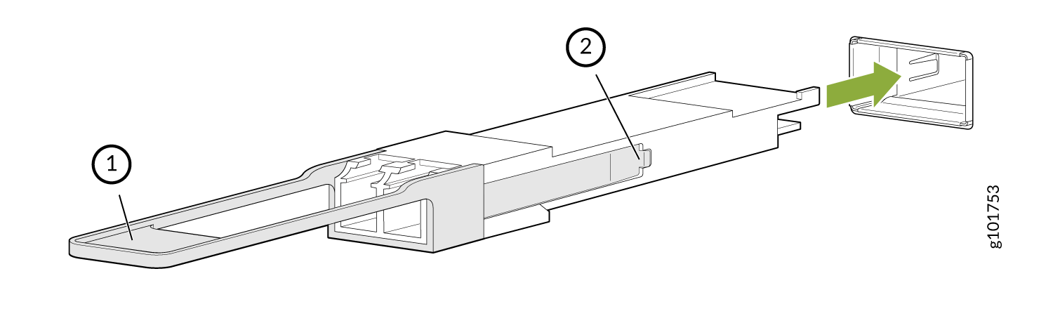
To install a replacement QSFP56-DD transceiver (see Figure 7):
-
Orient the transceiver in front of the port so that the QSFP56-DD connector
faces the appropriate direction.
Figure 8: 400-Gbps Quad Small Form-Factor Pluggable (QSFP56-DD) Transceiver
Maintain Active Optical Cables
An active optical cable (AOC) is an optical fiber cable that has a transceiver preattached to each end.
Disconnect an Active Optical Cable
Before you disconnect an active optical cable (AOC) from a device, ensure that you have taken the necessary precautions for safe handling of laser (see Laser and LED Safety Guidelines and Warnings).
Ensure that you have the following parts and tools available:
-
An antistatic bag or an antistatic mat to store the cable, if you are disconnecting the cable from all the ports it is connected to
-
Rubber safety caps to cover the ports on the device, or a replacement cable
-
Rubber safety caps to cover the transceivers at the ends of the cable
-
An electrostatic discharge (ESD) grounding strap—not provided
To disconnect an active optical cable:
-
By using your fingers, pull the tab on the transceiver attached to the
cable to disengage
it.
Figure 9: Disconnect an SFP28 or SFP+ Active Optical Cable
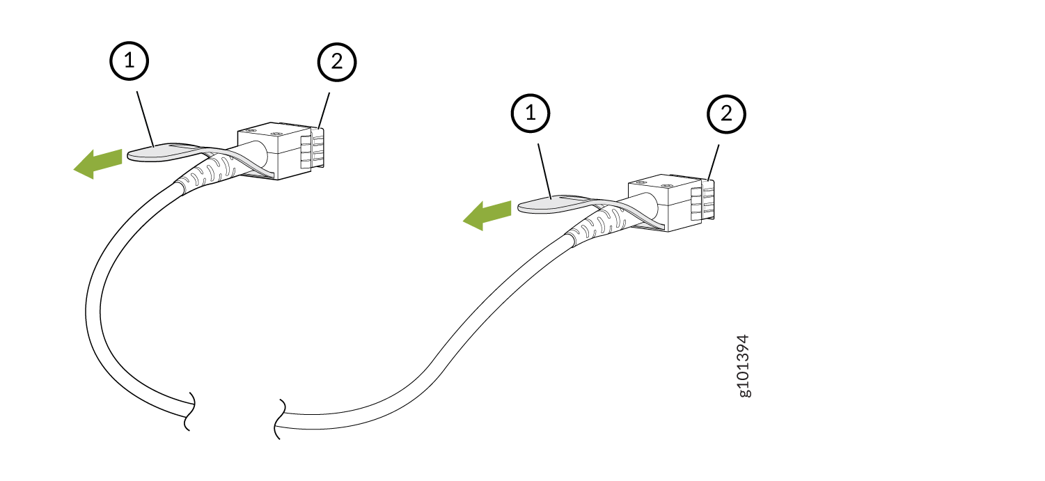 1—
1—Tab to pull the transceiver
2—Port on the device
Figure 10: Disconnect a QSFP28 or QSFP+ Active Optical Cable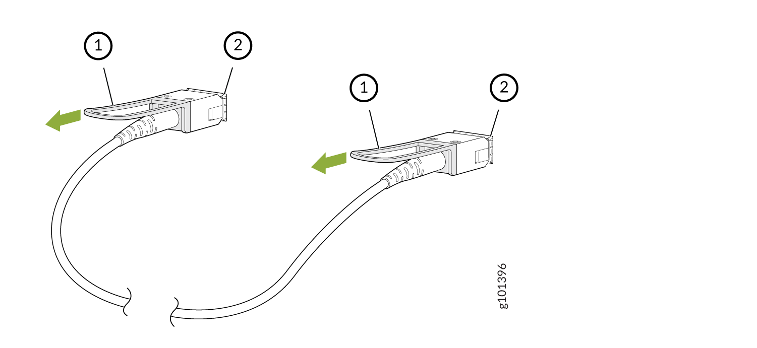 1—
1—Tab to pull the transceiver
2—Port on the device
The procedure to disconnect other types of AOCs, other than direct attach AOCs, is the same as the procedure described in this topic.
Connect an Active Optical Cable
Before you connect an AOC to a device, ensure that you have taken the necessary precautions for safe handling of lasers (see Laser and LED Safety Guidelines and Warnings).
To prevent electrostatic discharge (ESD) damage to the transceiver, do not touch the connector pins at the end of the transceiver.
Ensure that you have an ESD grounding strap (not provided).
After you connect a cable or after you change the media-type configuration, wait for 6 seconds for the interface to display operational commands.
We recommend that you use only cables purchased from Juniper Networks with your Juniper Networks device.
If you face a problem running a Juniper Networks device that uses a third-party optic or cable, the Juniper Networks Technical Assistance Center (JTAC) can help you diagnose the source of the problem. Your JTAC engineer might recommend that you check the third-party optic or cable and potentially replace it with an equivalent Juniper Networks optic or cable that is qualified for the device.
To connect an active optical cable:
-
By using both hands, carefully insert the transceiver in the empty port.
The connectors must face the chassis. Slide the transceiver in gently until
it is fully
seated.
Figure 11: Connect an SFP28 or SFP+ Active Optical Cable
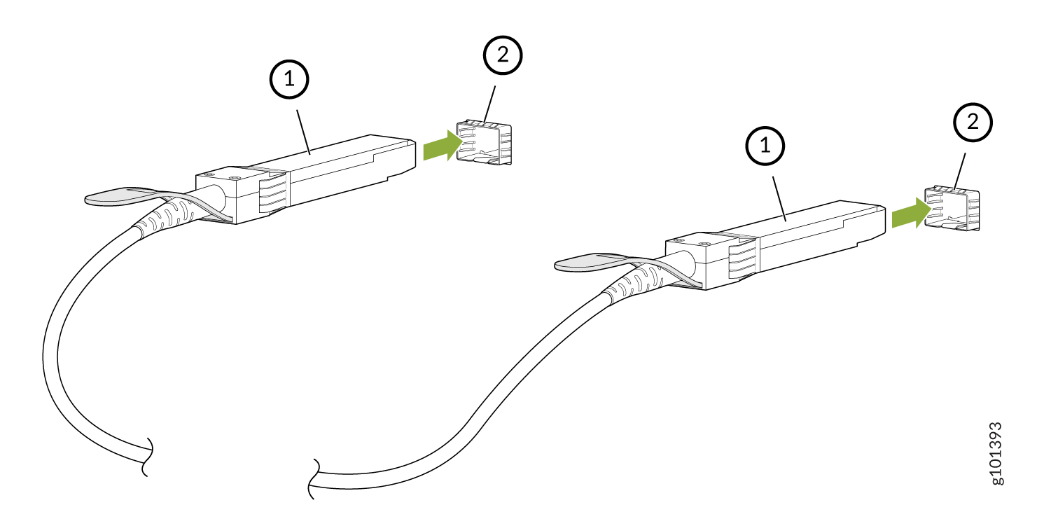 1—
1—Transceiver
2—Port on the device
Figure 12: Connect a QSFP28 or QSFP+ Active Optical Cable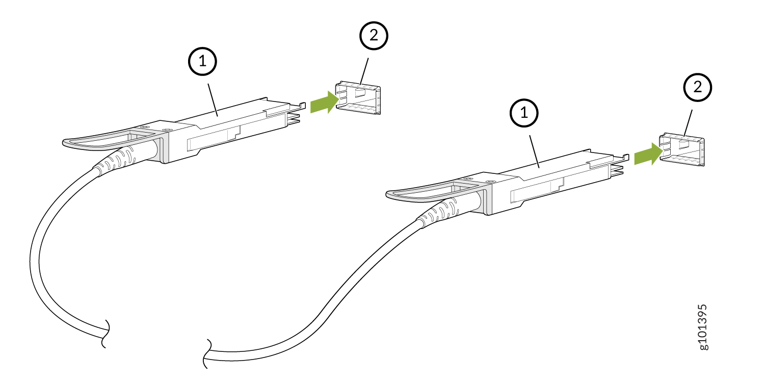 1—
1—Transceiver
2—Port on the device
The procedure to connect other types of AOCs, other than direct attach AOCs, is the same as the procedure described in this topic.
Maintain Breakout Cables
Breakout cables have one transceiver preattached to one end and more than one transceiver preattached to the other end. You can use the cables to channelize a port and increase the number of interfaces. For example, you can channelize the QSFP28 ports on the front panel of MX304 by connecting breakout cables and by using CLI configuration when those ports are configured as network ports (see Port Speed on MX304 Router Overview).
Disconnect a Breakout Cable
Before you disconnect a breakout cable from a device, ensure that you have taken the necessary precautions for safe handling of laser (see Laser and LED Safety Guidelines and Warnings).
Ensure that you have the following parts and tools available:
An antistatic bag or an antistatic mat to store the cable, if you are disconnecting the cable from all the ports it is connected to
Rubber safety caps to cover the ports on the device, or a replacement cable
Rubber safety caps to cover the transceivers at the ends of the cable
An electrostatic discharge (ESD) grounding strap—not provided
To disconnect a breakout cable:
- By using your fingers, pull the tab on the transceiver
attached to the cable to disengage it (see Figure 13).Figure 13: Disconnect a Breakout Cable
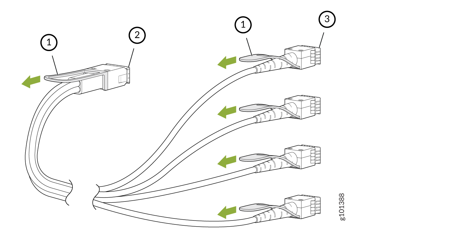 1—
1—Tab to pull the transceiver
3—Port at the other end
2—Channelized port on a device
The procedure to disconnect other types of breakout cables is the same as the procedure described in this topic.
Connect a Breakout Cable
To prevent ESD damage to the transceiver, do not touch the connector pins at the end of the transceiver.
If you are connecting an active optic breakout cable to a device, ensure that you have taken the necessary precautions for safe handling of laser (see Laser and LED Safety Guidelines and Warnings).
Ensure that you have an electrostatic discharge (ESD) grounding strap (not provided).
After you connect a cable or after you change the media-type configuration, wait for 6 seconds for the interface to display operational commands.
We recommend that you use only cables purchased from Juniper Networks with your Juniper Networks device.
If you face a problem running a Juniper Networks device that uses a third-party optic or cable, the Juniper Networks Technical Assistance Center (JTAC) can help you diagnose the source of the problem. Your JTAC engineer might recommend that you check the third-party optic or cable and potentially replace it with an equivalent Juniper Networks optic or cable that is qualified for the device.
To connect a breakout cable:
- By using both hands, carefully insert the transceiver
in the empty port. The connectors must face the chassis. Slide the
transceiver in gently until it is fully seated (see Figure 14).Figure 14: Connect a Breakout Cable
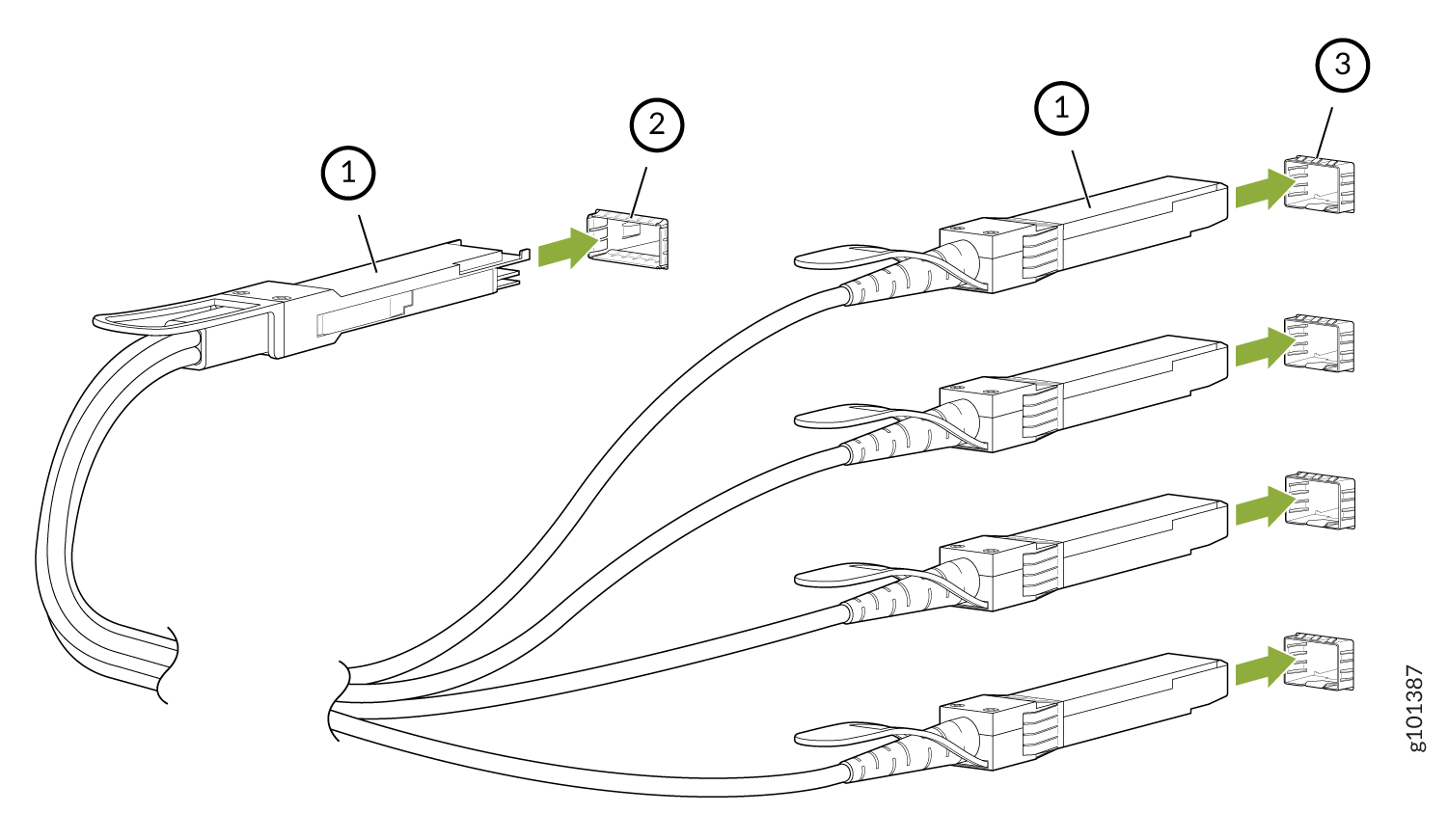 1—
1—Transceiver
3—Ports at the other end
2—Channelized port on a device
The procedure to connect other types of breakout cables is the same as the procedure described in this topic.
Maintain Direct Attach Cables
A direct attach cable has a transceiver preattached to each end.
Disconnect a Direct Attach Cable
Ensure that you have the following parts and tools available:
-
An antistatic bag or an antistatic mat to store the cable, if you are disconnecting the cable from both the ports it is connected to
-
Rubber safety caps to cover the ports on the device, or a replacement cable
-
Rubber safety caps to cover the transceivers at the ends of the cable
-
An electrostatic discharge (ESD) grounding strap—not provided
To disconnect a direct attach cable:
-
By using your fingers, pull the tab on the transceiver attached to the
cable to disengage
it.
Figure 15: Disconnect an SFP28 or SFP+ Direct Attach Cable
1—
Tab to pull the transceiver
2—Port on the device
Figure 16: Disconnect a SFP28, SFP+, or QSFP-DD Direct Attach Cable
1—Tab to pull the transceiver
2—Port on the device
The procedure to disconnect other types of direct attach cables, other than direct attach breakout cables, is the same as the procedure described in this topic.
Connect a Direct Attach Cable
To prevent ESD damage to the transceiver, do not touch the connector pins at the end of the transceiver.
Ensure that you have an ESD grounding strap (not provided).
After you connect a cable or after you change the media-type configuration, wait for 6 seconds for the interface to display operational commands.
We recommend that you use only cables purchased from Juniper Networks with your Juniper Networks device.
If you face a problem running a Juniper Networks device that uses a third-party optic or cable, the Juniper Networks Technical Assistance Center (JTAC) can help you diagnose the source of the problem. Your JTAC engineer might recommend that you check the third-party optic or cable and potentially replace it with an equivalent Juniper Networks optic or cable that is qualified for the device.
To connect a direct attach cable:
-
By using both hands, carefully insert the transceiver in the empty port.
The connectors must face the chassis. Slide the transceiver in gently until
it is fully
seated.
Figure 17: Connect an SFP28 or SFP+ Direct Attach Cable
1—
Transceiver
2—Port on the device
Figure 18: Connect a SFP28, SFP+, or QSFP-DD Direct Attach Cable
1—Transceiver
2—Port on the device
The procedure to connect other types of direct attach cables, other than direct attach breakout cables, is the same as the procedure described in this topic.