MX240 DC Power System
MX240 DC Power Supply Description
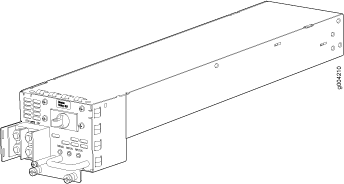
Each DC power supply weighs approximately 3.8 lb (1.7 kg) and consists of one DC input (–48 VDC and return), one 40 A (–48 VDC) circuit breaker, a fan, and LEDs to monitor the status of the power supply. Each DC power supply requires a dedicated customer site circuit breaker. For normal capacity power supplies, we recommend a dedicated circuit breaker rated for 40 A (–48 VDC) minimum, or as required by local code.
For high capacity power supplies, we recommend that you provision 60 A or 70 A per feed, depending on the selected DIP switch setting.
Figure 1 shows the normal capacity DC power supply.
Figure 2 shows the high-capacity DC power supply.
DC Power Supply Configurations
In the DC power configuration, the router contains either one or two DC power supplies located at the rear of the chassis in slots PEM0 and PEM2 (left to right). You can upgrade your DC power system from one to two power supplies. A single DC power supply provides power to all components. A second DC power supply provides redundancy. If a DC power supply in a redundant configuration fails, the redundant power supply takes over without interruption.
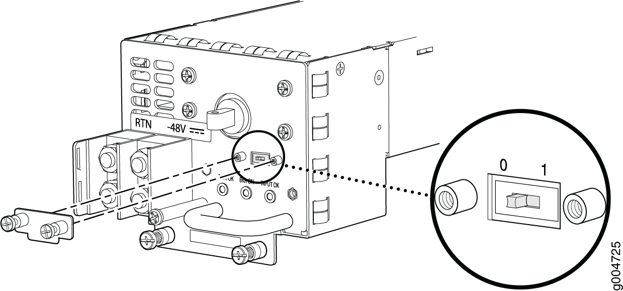
High-capacity DC power supplies have a DIP switch that selects the power output.
Move the input switch to 0 for 60 A input and position 1 for 70 A input.
Do not set the input mode switch if the power supply is installed in the chassis. If the power supply is already installed, you must remove it before setting the input mode switch.
Table 1 shows the components that are powered by each DC power supply slot. The specifications apply to normal capacity and high-capacity power supplies.
DC Power Supply Slot |
Power Supply Provides Power to the Following Components |
|---|---|
PEM0 |
Fan tray, DPC slots 0, 1, and 2, and SCB slots 0 and 1 |
PEM2 |
Fan tray, DPC slots 0, 1, and 2, and SCB slots 0 and 1 |
See Also
MX240 DC Power Supply LEDs
Each DC power supply faceplate contains three LEDs that indicate the status of the power supply (see Table 2). The power supply status is also reflected in two LEDs on the craft interface (see MX240 Component LEDs on the Craft Interface).In addition, a power supply failure triggers the red alarm LED on the craft interface.
An SCB must be present for the PWR OK LED to go on.
Label |
Color |
State |
Description |
|---|---|---|---|
PWR OK |
Green |
Off |
Power supply is not functioning normally. Check the INPUT OK LED for more information. |
On |
Power supply is functioning normally. |
||
Yellow |
On |
The main output voltage is out of range (lower limit: 37.5 V to 39.5 V; upper limit: 72.5 V to 76 V). |
|
BRKR ON |
Green |
Off |
DC power supply circuit breaker is turned off. |
On |
DC power input is present and the DC power supply circuit breaker is turned on. |
||
INPUT OK |
Green |
Off |
DC input to the PEM is not present. |
On |
DC input is present and is connected in correct polarity. |
||
Yellow |
On |
DC input is present, but not in valid operating range or connected in reverse polarity. |
See Also
DC Power Supply Electrical Specifications for MX240 and MX480
Table 3 lists the DC power supply electrical specifications. Table 4 lists the DC power system specifications.
Item |
Specification |
|
|---|---|---|
| Normal-Capacity Power Supplies | ||
|
Maximum output power |
1600 W |
|
|
DC input current rating |
33.3 A @ –48 V nominal operating voltage |
|
|
Maximum Input Current |
40 A |
|
|
DC input voltage |
Operating Range: –40.5 VDC to –72 VDC Nominal: –48 VDC |
|
|
Efficiency Note:
This value is at full load and nominal voltage. |
~98% |
|
| Maximum Inrush |
The peak of inrush current caused by X-capacitors across input of the PEM shall not exceed 200A for less than 10mSecond. Measurement has to be done with Tektronix current probe and a scope with bandwidth 250MHz. The PEM also shall limit the I²t transient to 5A2S maximum at cold start. No damage shall occur to the PEM from repeated on/off/on cycles under hot or cold conditions. |
|
|
Internal Circuit Breaker |
40 A |
|
| High-Capacity Power Supplies | ||
|
Maximum Input Current |
60 A (DIP=0) |
70 A (DIP=1) |
|
Maximum output power |
2240 W |
2440 W |
|
DC input current rating |
50 A @ -48 VDC normal operating voltage |
54.2 A @ -48 VDC normal operating voltage |
|
DC input voltage |
Operating Range: –40.5 VDC to –72 VDC Nominal: –48 VDC |
|
|
Efficiency Note:
This value is at full load and nominal voltage. |
~98% |
|
| Maximum Inrush |
The peak of inrush current caused by X-capacitors across input of the PEM shall not exceed 200A for less than 10mSecond. Measurement has to be done with Tektronix current probe and a scope with bandwidth 250MHz. The PEM also shall limit the I²t transient to 5A2S maximum at cold start. No damage shall occur to the PEM from repeated on/off/on cycles under hot or cold conditions. |
|
Item |
Normal-Capacity |
High-Capacity |
|
|---|---|---|---|
Redundancy |
2+2 |
1+1 |
|
Output power (maximum) per supply |
1600 W |
60 A (DIP=0) |
70 A (DIP=1) |
2240 W |
2440 W |
||
Output power (maximum) per system |
3200 W |
2240 W |
2240 W |
See Also
DC Power Circuit Breaker Requirements for the MX240 Router
Each DC power supply has a single DC input (–48 VDC and return) that requires a dedicated circuit breaker. We recommend that you use a dedicated customer site circuit breaker rated for 40 A (–48 VDC) minimum, or as required by local code. Doing so enables you to operate the router in any configuration without upgrading the power infrastructure.
For high-capacity power supplies, we recommend that you use a dedicated customer site circuit breaker rated for 60 A or 70A, or as required by local code,depending on the input switch setting.
If you plan to operate a DC-powered router at less than the maximum configuration and do not provision a 40 A (–48 VDC) circuit breaker, we recommend that you provision a dedicated customer site circuit breaker for each DC power supply rated for at least 125% of the continuous current that the system draws at –48 VDC.
See Also
MX240 Chassis Grounding Specifications
- MX240 Chassis Grounding Points Specifications
- MX240 Router Grounding Cable Lug Specifications
- MX240 Router Grounding Cable Specifications
MX240 Chassis Grounding Points Specifications
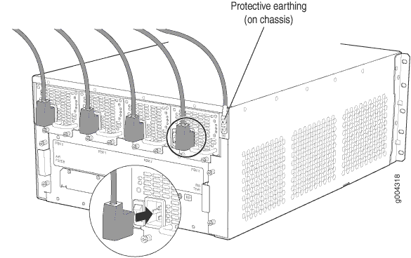
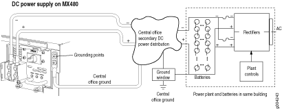
To meet safety and electromagnetic interference (EMI) requirements and to ensure proper operation, the router must be adequately grounded before power is connected. To ground AC-powered and DC-powered routers, you must connect a grounding cable to earth ground and then attach it to the chassis grounding points using the two screws provided.
Two threaded inserts (PEM nuts) are provided on the upper rear of the chassis for connecting the router to earth ground. The grounding points fit UNC 1/4–20 screws (American). The grounding points are spaced at 0.625-in. (15.86-mm) centers.
See Figure 3 for connecting AC power to the router and Figure 4 for connecting DC power to the router.
Additional grounding is provided to an AC-powered router when you plug its power supplies into grounded AC power receptacles.
You must install the MX240 router in a restricted-access location and ensure that the chassis is always properly grounded. The MX240 router has a two-hole protective grounding terminal provided on the chassis. See Figure 3 and Figure 4. We recommend that you use this protective grounding terminal as the preferred method for grounding the chassis regardless of the power supply configuration. However, if additional grounding methods are available, you can also use those methods. For example, you can use the grounding wire in the AC power cord or use the grounding terminal or lug on a DC power supply. This tested system meets or exceeds all applicable EMC regulatory requirements with the two-hole protective grounding terminal.
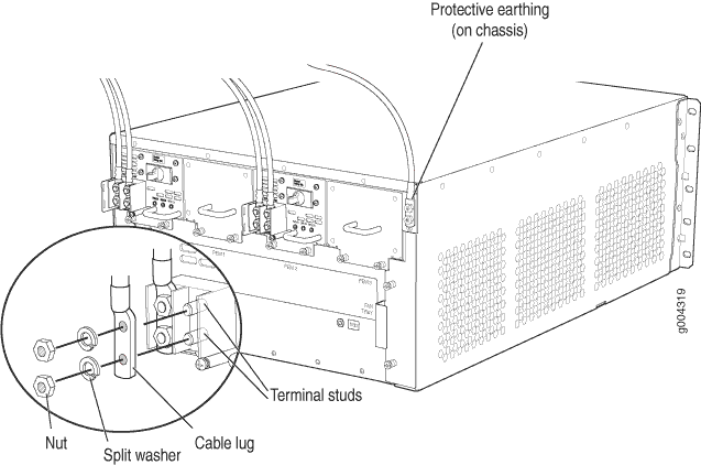
MX240 Router Grounding Cable Lug Specifications
The accessory box shipped with the router includes one cable lug that attaches to the grounding cable (see Figure 5) and two UNC 1/4–20 screws used to secure the grounding cable to the grounding points.
Before you install the router, a licensed electrician must attach a cable lug to the grounding and power cables that you supply. A cable with an incorrectly attached lug can damage the router.
The same cable lug is used for the DC power cables.
MX240 Router Grounding Cable Specifications
You must provide one grounding cable that meets the following specifications: 6-AWG (13.3 mm2), minimum 60°C wire, or as required by the local code.
See Also
DC Power Source Cabling for the MX240 Router
Figure 6 shows a typical DC source cabling arrangement.
The DC power supply in PEM0 must be powered by a dedicated power feed derived from feed A, and the DC power supply in PEM2 must be powered by a dedicated power feed derived from feed B. This configuration provides the commonly deployed A/B feed redundancy for the system.
You must ensure that power connections maintain the proper polarity. The power source cables might be labeled (+) and (–) to indicate their polarity. There is no standard color coding for DC power cables. The color coding used by the external DC power source at your site determines the color coding for the leads on the power cables that attach to the terminal studs on each power supply.
For field-wiring connections, use copper conductors only.
Power cords and cables must not block access to device components or drape where people could trip on them.
See Also
DC Power Cable Specifications for the MX240 Router
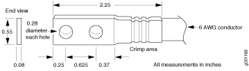
DC Power Cable Lug Specifications—The accessory box shipped with the router includes the cable lugs that attach to the terminal studs of each power supply (see Figure 7).
Before you install the router, a licensed electrician must attach a cable lug to the grounding and power cables that you supply. A cable with an incorrectly attached lug can damage the router.
The same cable lug is used for the grounding cable.
DC Power Cable Specifications—You must supply four DC power cables that meet the following specifications: 6-AWG (13.3 mm2), minimum 60° C wire, or as required by the local code.
See Also
Outstanding Issues with the MX240 Router
This topic lists outstanding hardware issues with the MX240 router. For information about software issues, see the Junos OS Release Notes.
On the MX240 DC high capacity power supplies, the input mode switch tells the system what capacity feed is connected (60A or 70A). This is used for power inventory management. When the input mode switch is set to '0' (zero): expect 60A feeds, with a voltage range of -39V to -72VDC. When the input mode switch is set to '1' (one), expect either a 70A feed or a 60A feed with minimum voltage of 42V and up. The default setting of the input mode is 1 (e.g. 60A with voltages above 42VDC, or 70A).
Known bug: In Junos OS Releases 10.0R3, 10.1R2, and 10.2R1, the MX240 DC high capacity power supply input mode switch status is not properly reflected in the power inventory management, generating alarms incorrectly. This does not have any effect on the operation of the supply. [PR532230]
Important notes:
All supplies should have the same feed setting.
Correct usage of the feed setting is required for all supplies in order to get the desired power inventory management.
The XFP cages and optics on the MX240 router are industry standard parts that have limited tactile feedback for insertion of optics and fiber. You need to insert the optics and fiber firmly until the latch is securely in place. [PR/98055]
Do not mix AC and DC power supplies on an MX240 router. Mixing of AC supplies and DC supplies may damage your chassis. [PR/233340]