Maintaining MX240 Power System Components
Maintaining the MX240 Power Supplies
Purpose
For optimum router performance, verify the condition of the power supplies.
Action
On a regular basis:
PEM 0 status:
  State                           Online
  Temperature                     OK
  DC output                       OK
PEM 2 status:
  State                           Online
  Temperature                     OK
  DC output                       OK
Make sure that the power and grounding cables are arranged so that they do not obstruct access to other router components.
Routinely check the status LEDs on the power supply faceplates and the craft interface to determine if the power supplies are functioning normally.
Check the red and yellow alarm LEDs on the craft interface. Power supply failure or removal triggers an alarm that causes one or both of the LEDs to light. You can display the associated error messages by issuing the following command:
user@host> show chassis alarms
Periodically inspect the site to ensure that the grounding and power cables connected to the router are securely in place and that there is no moisture accumulating near the router.
See Also
Replacing an MX240 AC Normal-Capacity Power Supply
- Removing an MX240 AC Normal-Capacity Power Supply
- Installing an MX240 AC Normal-Capacity Power Supply
Removing an MX240 AC Normal-Capacity Power Supply
Before you remove a power supply, be aware of the following:
The minimum number of power supplies must be present in the router at all times.
To maintain proper cooling and prevent thermal shutdown of the operating power supply unit, each power supply slot must contain either a power supply or a blank panel. If you remove a power supply, you must install a replacement power supply or a blank panel shortly after the removal.
After powering off a power supply, wait at least 60 seconds before turning it back on.
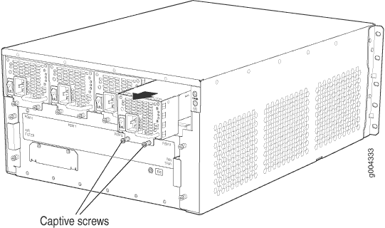
To remove an AC power supply (see Figure 1):
- Switch off the dedicated customer site circuit breaker for the power supply, and remove the power cord from the AC power source. Follow the instructions for your site.
- Attach an ESD grounding strap to your bare wrist, and connect the other end of the strap to an ESD grounding point.
- Move the AC input switch next to the appliance inlet on the power supply to the off (O) position.
- Remove the power cord from the power supply.
- Unscrew the captive screws on the bottom edge of the power supply.
- Pull the power supply straight out of the chassis.
See Also
Installing an MX240 AC Normal-Capacity Power Supply
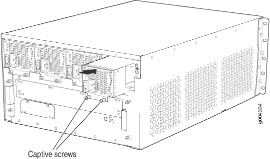
To install an AC power supply (see Figure 2):
- Attach an ESD grounding strap to your bare wrist, and connect the other end of the strap to an ESD grounding point.
- Move the AC input switch next to the appliance inlet on the power supply to the off (O) position.
- Using both hands, slide the power supply straight into the chassis until the power supply is fully seated in the chassis slot. The power supply faceplate should be flush with any adjacent power supply faceplate or blank installed in the power supply slot.
- Tighten both captive screws at the bottom of the power supply.
- Attach the power cord to the power supply.
- Attach the power cord to the AC power source, and switch on the dedicated customer site circuit breaker. Follow the instructions for your site.
- Move the AC input switch next to the appliance inlet on the power supply to the on (|) position and observe the status LEDs on the power supply faceplate. If the power supply is correctly installed and functioning normally, the AC OK and DC OK LEDs light steadily, and the PS FAIL LED is not lit.
Replacing an MX240 AC Power Supply Cord
Disconnecting an MX240 AC Power Supply Cord
To disconnect the AC power cord:
- Switch off the dedicated customer site circuit breaker for the power supply, and remove the power cord from the AC power source. Follow the instructions for your site.
- Attach an ESD grounding strap to your bare wrist, and connect the other end of the strap to an ESD grounding point.
- Move the AC input switch next to the appliance inlet on
the power supply to the off (
O) position. - Remove the power cord from the power supply.
Connecting an MX240 AC Power Supply Cord
To connect the AC power cord:
- Locate a replacement power cord with the type of plug appropriate for your geographical location (see AC Power Cord Specifications for the MX240 Router).
- Connect the power cord to the power supply.
- Insert the power cord plug into an external AC power source receptacle.
- Route the power cord appropriately. Verify that the power cord does not block the air exhaust and access to router components, or drape where people could trip on it.
- Switch the AC input switch on the each power supply to the on (|) position and observe the status LEDs on the power supply faceplate. If the power supply is correctly installed and functioning normally, the AC OK and DC OK LEDs light steadily, and the PS FAIL LED is not lit.
Replacing an MX240 DC Normal-Capacity Power Supply
Removing an MX240 DC Power Supply
Before you remove a power supply, be aware of the following:
The minimum number of power supplies must be present in the router at all times.
Before you perform DC power procedures, ensure there is no power to the DC circuit. To ensure that all power is off, locate the circuit breaker on the panel board that services the DC circuit, switch the circuit breaker to the off position, and tape the switch handle of the circuit breaker in the off position.
To maintain proper cooling and prevent thermal shutdown of the operating power supply unit, each power supply slot must contain either a power supply or a blank panel. If you remove a power supply, you must install a replacement power supply or a blank panel shortly after the removal.
After powering off a power supply, wait at least 60 seconds before turning it back on.
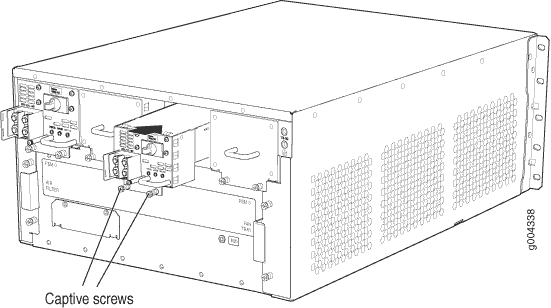
To remove a DC power supply (see Figure 3):
- Switch off the dedicated customer site circuit breaker for the power supply being removed. Follow your site's procedures for ESD.
- Make sure that the voltage across the DC power source cable leads is 0 V and that there is no chance that the cables might become active during the removal process.
- Attach an ESD grounding strap to your bare wrist, and connect the other end of the strap to an ESD grounding point.
- Move the DC circuit breaker on the DC power supply faceplate to the off (O) position.
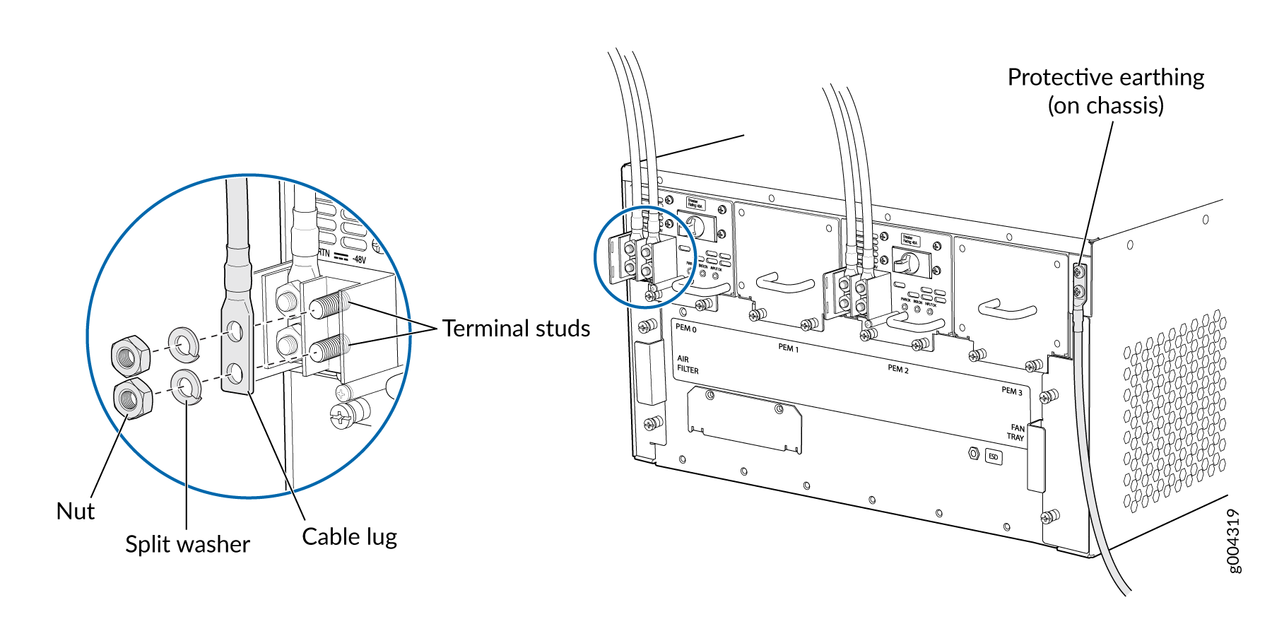
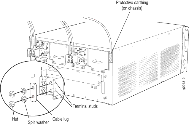
- Remove the clear plastic cover protecting the terminal studs on the faceplate.
- Remove the nut and washer from each of the terminal studs. (Use a 7/16-in. [11 mm] nut driver or socket wrench.)
- Remove the cable lugs from the terminal studs.
- Loosen the captive screws on the bottom edge of the power supply faceplate.
- Carefully move the power cables out of the way.
- Pull the power supply straight out of the chassis.

Installing an MX240 DC Normal Capacity Power Supply
Before you perform DC power procedures, ensure there is no power to the DC circuit. To ensure that all power is off, locate the circuit breaker on the panel board that services the DC circuit, switch the circuit breaker to the off position, and tape the switch handle of the circuit breaker in the off position.
To install a DC power supply (see Figure 4):
An SCB must be present for the PWR OK LED to go on.
Replacing an MX240 DC Power Supply Cable
Disconnecting an MX240 DC Power Supply Cable
Before you perform DC power procedures, ensure there is no power to the DC circuit. To ensure that all power is off, locate the circuit breaker on the panel board that services the DC circuit, switch the circuit breaker to the off position, and tape the switch handle of the circuit breaker in the off position.
To disconnect a power cable for a DC power supply:
- Switch off the dedicated customer site circuit breaker for the power supply being removed. Follow your site's procedures for ESD.
- Make sure that the voltage across the DC power source cable leads is 0 V and that there is no chance that the cables might become active during the removal process.
- Verify that the INPUT OK LED on the power supply is not lit.
- Remove the power cable from the external DC power source.
- Attach an ESD grounding strap to your bare wrist, and connect the other end of the strap to an ESD grounding point.
- Switch the DC circuit breaker on the DC power supply faceplate to the off (O) position.
- Remove the clear plastic cover protecting the terminal studs on the faceplate.
- Remove the nut and washer from each of the terminal studs. (Use a 7/16-in. [11 mm] nut driver or socket wrench.)
- Remove the cable lug from the terminal studs.
- Carefully move the power cable out of the way.
Connecting an MX240 DC Power Supply Cable
Before you perform DC power procedures, ensure there is no power to the DC circuit. To ensure that all power is off, locate the circuit breaker on the panel board that services the DC circuit, switch the circuit breaker to the off position, and tape the switch handle of the circuit breaker in the off position.
To connect a power cable for a DC power supply:
-
Install heat-shrink tubing insulation around the power
cables.
To install heat-shrink tubing:
-
Slide the tubing over the portion of the cable where it is attached to the lug barrel. Ensure that tubing covers the end of the wire and the barrel of the lug attached to it.
-
Shrink the tubing with a heat gun. Ensure that you heat all sides of the tubing evenly so that it shrinks around the cable tightly.
Figure 6 shows the steps to install heat-shrink tubing.
Note:Do not overheat the tubing.
Figure 6: How to Install Heat-Shrink Tubing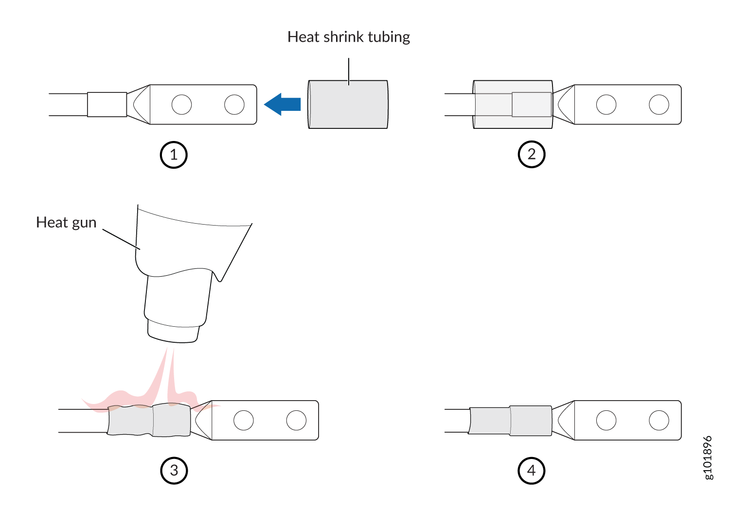
-
-
Secure the power cable lug to the terminal studs, first with the flat washer,
then with the nut. Apply between 23 lb-in. (2.6 Nm) and 25 lb-in. (2.8 Nm) of
torque to each nut (see Figure 7). Do not
overtighten the nut. (Use a 7/16-in. [11 mm] torque-controlled driver or socket
wrench.)
CAUTION:
Ensure that each power cable lug seats flush against the surface of the terminal block as you are tightening the nuts. Ensure that each nut is properly threaded onto the terminal stud. The nut should be able to spin freely with your fingers when it is first placed onto the terminal stud. Applying installation torque to the nut when improperly threaded may result in damage to the terminal stud.
CAUTION:The maximum torque rating of the terminal studs on the DC power supply is 36 lb-in. (4.0 Nm). The terminal studs may be damaged if excessive torque is applied. Use only a torque-controlled driver or socket wrench to tighten nuts on the DC power supply terminal studs.
Figure 7: Connecting DC Power to the Router