Help us improve your experience.

Let us know what you think.

Do you have time for a two-minute survey?


Connecting the MX2008 to High-Voltage Power

Installing MX2000 Router High-Voltage Universal (HVAC/HVDC) Power Supply Modules

To install an MX2000 high-voltage second-generation universal (HVAC/HVDC) PSM:

  1. Verify that the power switches on all PSMs are in the off (O) position.
  2. On the PSM, slide the plastic cover away from the input mode switch to expose the dual DIP switches. Move the input mode DIP switch 0 (left switch) to the ON position for the bottom feed INP0 (expected to be connected), and DIP switch 1 (middle switch) to the ON position for the top feed INP1 (expected to be connected). If both DIP switches 0 and 1 are turned to the ON position, then both top and bottom feeds are expected to be connected, (see Figure 1).

    In addition, a PSM failure triggers the alarm LED on the craft interface.

    Note:

    The DIP switches are only used to indicate presence of a feed. If both feeds are present, power is always drawn from feed 0. Power will be drawn from feed 1 only if feed 0 fails.

    Figure 1: Selecting Input Feed on the Universal (HVAC/HVDC) Power Supply ModuleSelecting Input Feed on the Universal (HVAC/HVDC) Power Supply Module
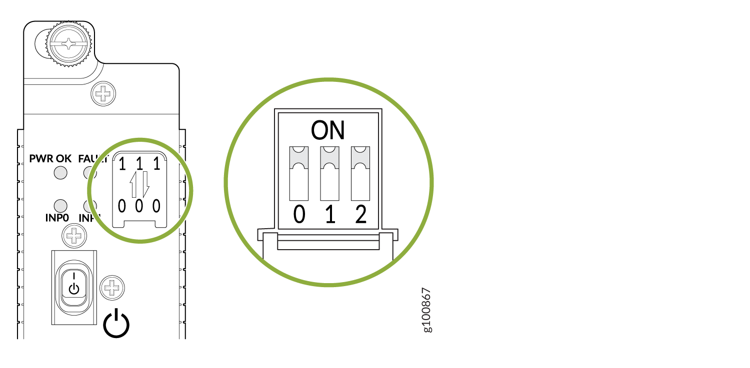
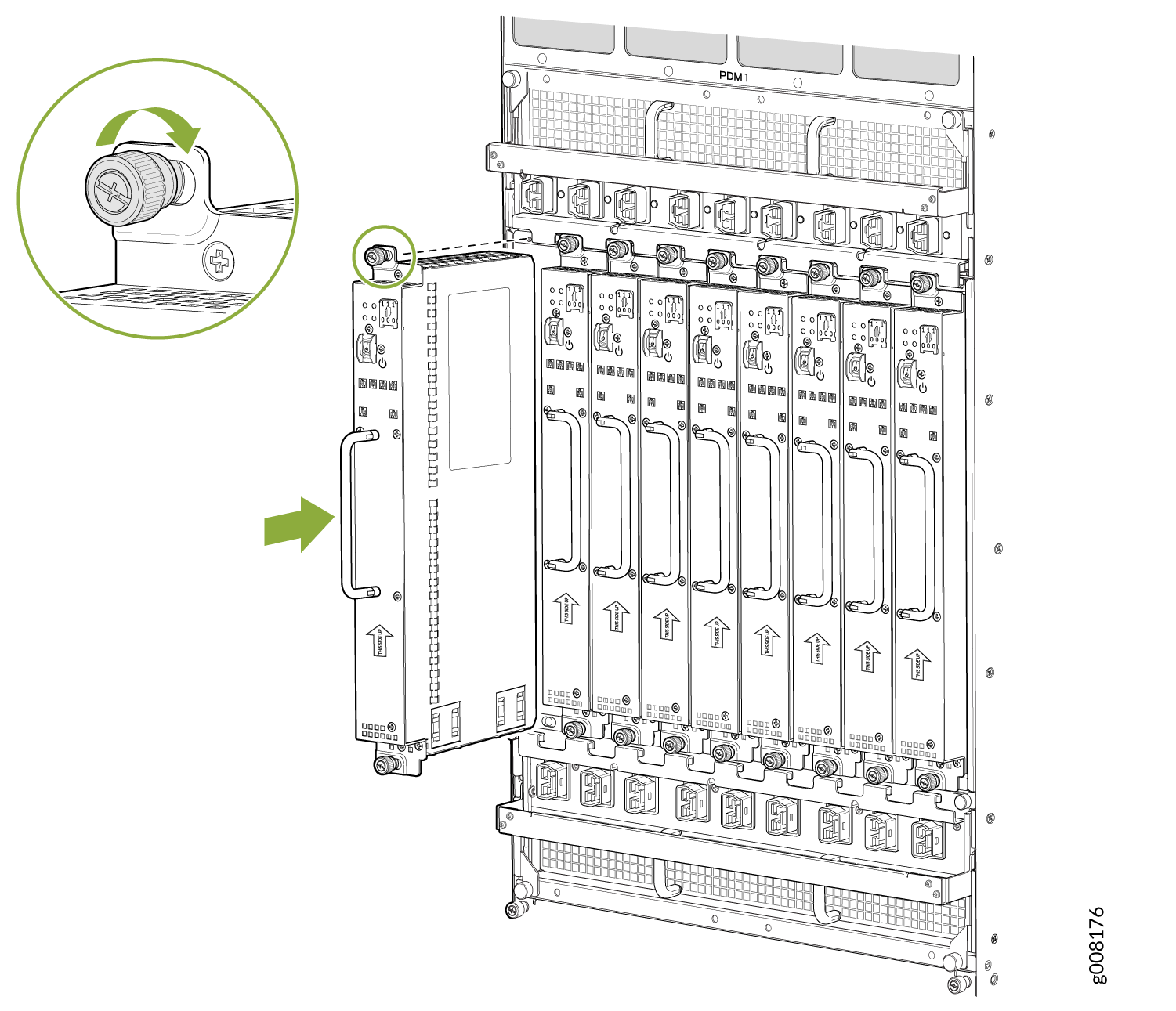
  3. Using both hands, grasp the handle and slide the PSM straight into the chassis until the PSM is fully seated in the chassis slot. Tighten the two captive screws (see Figure 2). Apply between 10 lb-in. (1.13 Nm) to 12 lb-in. (1.35 Nm) of torque to each screw. Do not overtighten the screws.
    Figure 2: Installing an MX2000 Router High-Voltage Universal (HVAC/HVDC) PSM Installing an MX2000 Router High-Voltage Universal (HVAC/HVDC) PSM
  4. Verify that the INP0 and/or INP1 LEDs on the PSM are lit green steadily (see Figure 3).
    Note:

    If you are connecting two feeds, INP0 and INP1, both LEDs on the PSM will be lit green steadily.

  5. Attach an electrostatic discharge (ESD) grounding strap to your bare wrist, and connect the strap to one of the ESD points on the chassis.
  6. Move the switch to the on (|) position.
  7. Verify that the PWR OK LED is lit green steadily. See MX2020 High-Voltage Universal Power Supply Module LEDs, MX2010 High-Voltage Universal (HVAC/HVDC) Power Supply Module LEDs, or MX2008 High-Voltage Universal Power Supply Module LEDs.
  8. Repeat Steps 1 through 7 for installing PSMs in slots 0, 1, and 2, where required.
    Figure 3: Selecting Input Feed on the Universal (HVAC/HVDC) Power Supply ModuleSelecting Input Feed on the Universal (HVAC/HVDC) Power Supply Module
    Note:

    Each PSM slot not occupied by a universal (HVAC/HVDC) PSM must be covered by a PSM blank panel.

Connecting Power to a High Voltage-Powered MX2000 Router with Power Distribution Modules

Warning:

Before performing DC power procedures, ensure that power is removed from the DC circuit. To ensure that all power is OFF, locate the circuit breaker on the panel board that services the DC circuit, switch the circuit breaker to the OFF position, and tape the switch handle of the circuit breaker in the OFF position.

Note:

Ensure that you have connected the chassis to earth ground. See Grounding an MX2000 Router.

You connect AC or DC power to the router by connecting the power cord from a universal (HVAC/HVDC) PDM to an AC or DC power source. See MX2000 High-Voltage Universal PDM (MX2K-PDM-HV) Power Cord Specifications for the list of supported power cords.

To connect the DC or AC source power cables to the router:

  1. Switch off the dedicated customer site circuit breakers. Ensure that the voltage across the AC or DC power source cable leads is 0 V and that there is no chance that the cable leads might become active during installation.
  2. Attach an electrostatic discharge (ESD) grounding strap to your bare wrist, and connect the strap to one of the ESD points on the chassis.
    Note:

    If the PSMs are installed in the router, make sure the power switches on all PSMs are turned to the off (O) position.

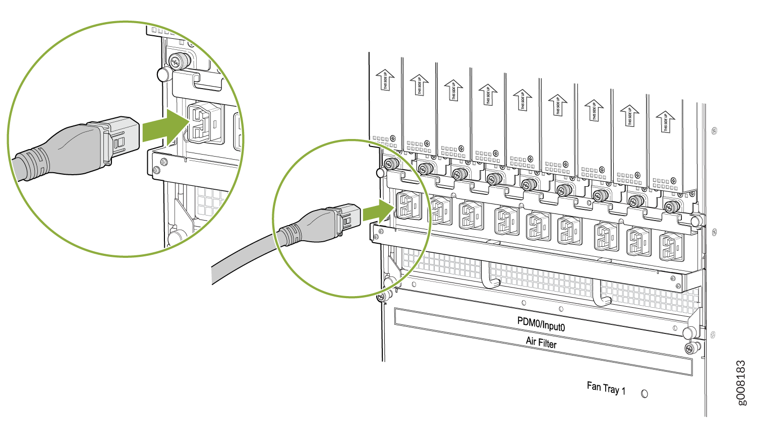
  3. Plug the power cord into the power sockets on the high-voltage second-generation universal (HVAC/HVDC) PDM . See Figure 1. Apply slight pressure so that the power cord is firmly seated in the power socket until you feel it engage. As you plug in each power cord, the power LED for the socket lights up green.
    Figure 4: Connecting Power to the Universal (HVAC/HVDC) PDMConnecting Power to the Universal (HVAC/HVDC) PDM
  4. Connect the power cords for the remaining PDMs.

Powering On the High-Voltage Powered Universal (HVAC/HVDC) MX2000 Router

To power on a high-voltage second-generation universal (HVAC/HVDC) powered router:

  1. Verify that an external management device is connected to one of the Routing Engine ports on the Control Board and Routing Engine (CB-RE) (AUX, CONSOLE, or MGMT).
  2. Turn on the power to the external management device.
  3. Verify that the PDMs are fully inserted in the chassis.
  4. Verify that the source power cables are connected to the PDM power cable.
  5. Switch on the dedicated customer site circuit breakers to provide power to the AC or DC power cables. Follow your site’s procedures.
  6. Check that the input labeled LEDs are lit green steadily, indicating the PDMs are installed and functioning normally.
    Note:

    Nine input LEDs indicate proper voltage level and polarity of input feeds.

  7. Attach an electrostatic discharge (ESD) grounding strap to your bare wrist, and connect the strap to one of the ESD points on the chassis.
  8. For each of the universal (HVAC/HVDC) PDMs installed, switch the AC or DC circuit breaker at the power source, moving it to the (ON) position.
  9. On each of the universal (HVAC/HVDC) PSMs, move the switch to the on (|) position.
  10. Verify that the PWR OK LED is lit green steadily, indicating the PSM is correctly installed and functioning normally.
    Note:

    After a PSM is powered on, it can take up to 60 seconds for status indicators—such as the status LEDs on the PSM and the show chassis command display—to indicate that the PSM is functioning normally. Ignore error indicators that appear during the first 60 seconds.

    If any of the status LEDs indicates that the PSM is not functioning normally, repeat the installation and cabling procedures.

  11. Verify that the INP0 or INP1 LEDs on the PSM are lit green steadily if using two feeds.
    Note:

    The DIP switches 0 and 1 must be set to the ON position for a two feed installation.

  12. On the external management device connected to the Control Board and Routing Engine (CB-RE), monitor the startup process to verify that the system has booted properly.
    Note:

    If the system is completely powered off when you power on the PSM, the Routing Engine boots as the PSM completes its startup sequence. Normally, the router boots from the Junos OS on the CompactFlash card.

    To power off the system after the Routing Engine finishes booting, see Powering Off the AC-Powered or Universal HVAC/HVDC-Powered MX2000 Router.

  13. Verify the MX2000 router power up, system initialization, and status, see Initially Configuring the MX2020 Router, Initially Configuring the MX2010 Router, or Initially Configuring the MX2008 Router.