Unpacking and Mounting the EX4650 Switch
Unpacking the Switch
EX4650 switches are shipped in a cardboard carton, secured with foam packing material. The carton has an accessory compartment and contains the quick start instructions.
EX4650 switches are maximally protected inside the shipping carton. Do not unpack the switches until you are ready to begin installation.
To unpack the switch:
- Move the shipping carton to a staging area as close to the installation site as possible, but where you have enough room to remove the system components.
- Position the carton so that the arrows marked on the carton are pointing up.
- Open the top flaps on the shipping carton.
- Pull out the packing material holding the switch in place.
- Verify the parts received against the inventory on the label attached to the carton.
- Save the shipping carton and packing materials in case you need to move or ship the switch later.
Parts Inventory (Packing List) for an EX4650 Switch
The switch shipment includes a packing list. Check the parts you receive with the switch against the items in the packing list. The packing list specifies the part number and provides a description of each part in your order. The parts shipped depend on the switch model you order.
If any part in the packing list is missing, contact your customer service representative or contact Juniper customer care from within the U.S. or Canada by telephone at 1-888-314-5822. For international-dial or direct-dial options in countries without toll-free numbers, see https://www.juniper.net/support/requesting-support.html .
Table 1 lists the parts and their quantities as listed in the standard packing list for an EX4650 switch.
Component |
Quantity |
|
|---|---|---|
Switch |
1 |
|
Fan modules |
EX4650 |
5 preinstalled |
Power supplies |
EX4650 |
2 (AC or DC) preinstalled |
AC power cord appropriate for your geographical location |
EX4650 |
2 |
Rack mount kit - JNP-4PST-RMK-1U-E (Partial toolless RMK) JNP-4PST-RMK-1U-E rack mount kit consists of the following parts:
Spare rack mount kits order numbers:
|
1 |
|
Quick Start installation instructions |
1 |
|
Juniper Networks Product Warranty |
1 |
|
End User License Agreement |
1 |
|
You must provide the appropriate mounting screws for mounting the switch on a rack.
Update Base Installation Data
Update the installation base data if any addition or change to the installation base occurs or if the installation base is moved. Juniper Networks is not responsible for not meeting the hardware replacement SLA for products that do not have accurate installation base data.
Update your installation base at https://supportportal.juniper.net/s/CreateCase .
Mount an EX4650-48Y Switch in a Rack or Cabinet by Using the JNP-4PST-RMK-1U-E Rack Mount Kit
You can mount EX4650-48Y switches on a square hole or threaded hole four-post 19-in. racks using the partial tool less JNP-4PST-RMK-1U-E rack mount kit.
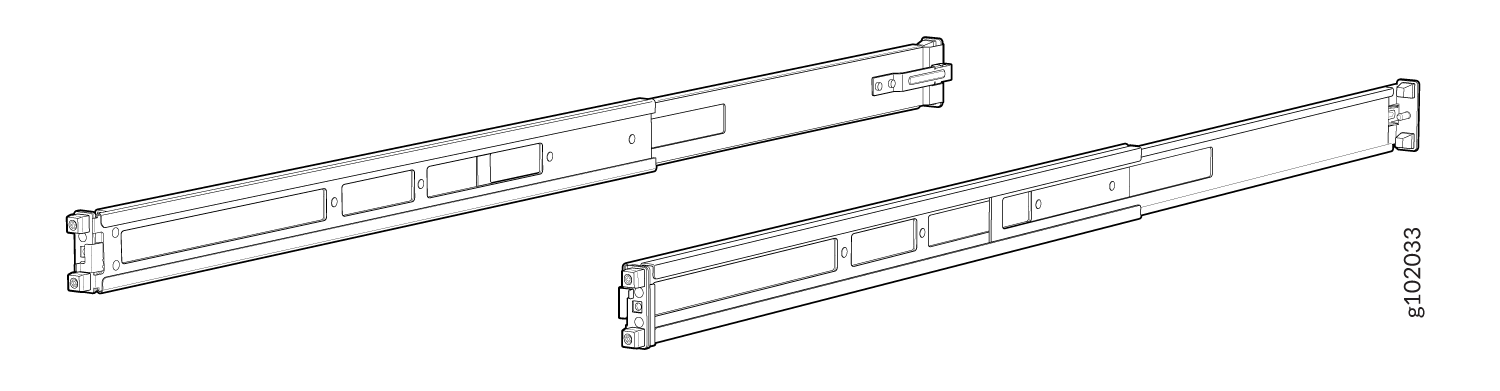
JNP-4PST-RMK-1U-E rack mount kit consists of the following parts:
-
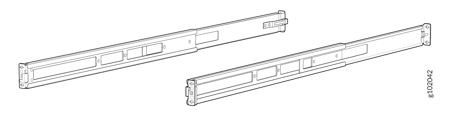
A pair of front and rear mounting rails
-
A pair of mounting brackets
-
16 flat head M4 x 6mm Phillips screws
A four-post installation evenly supports the device by all four corners.
- Mount the Device by Using the JNP-4PST-RMK-1U-E Rack Mount Kit On a Square Hole Rack
- Mount the Device by Using the JNP-4PST-RMK-1U-E Rack Mount Kit On a Threaded Hole Rack
Mount the Device by Using the JNP-4PST-RMK-1U-E Rack Mount Kit On a Square Hole Rack
Ensure that you have the following tools and parts available:
-
An ESD grounding strap—not provided.
-
Number 2 Phillips (+) screwdriver—not provided
-
A pair of front and rear mounting rails that attach to the rack posts—provided with the rack mount kit
-
A pair of mounting brackets and 16 flat head M4 x 6mm Phillips screws. These brackets attach to the device if not pre-installed—provided with the rack mount kit
To mount the device on four posts in a rack by using the JNP-4PST-RMK-1U-E rack mount kit:
- Assemble the mounting rails.
-
Attach the mounting rails to the rack.
-
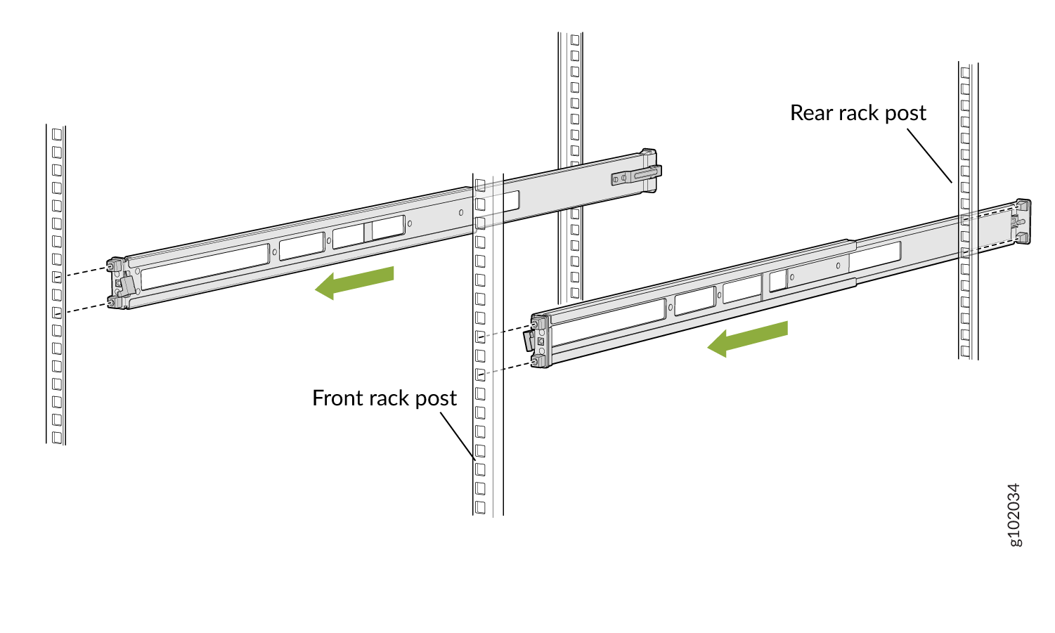
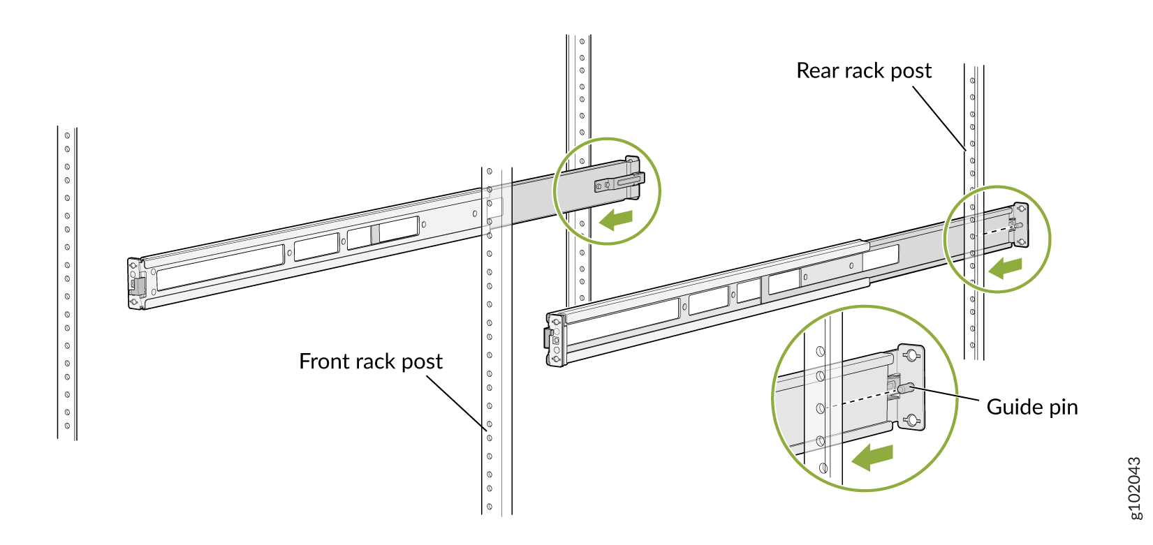
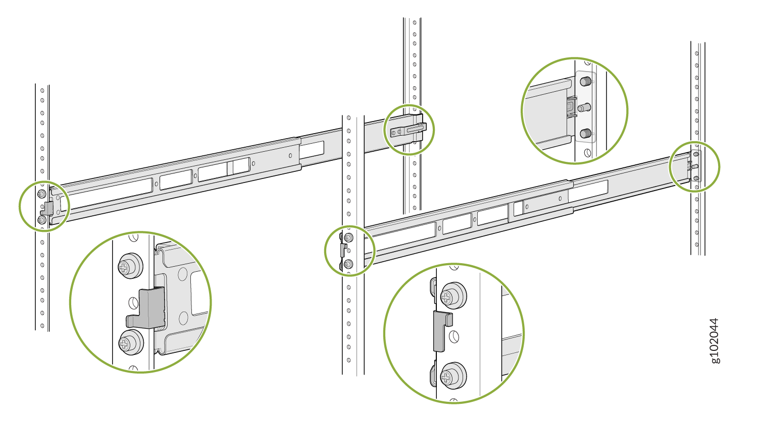
Align the guide blocks of the rear mounting rails with the rear-post holes. Pull
the rear mounting rails toward the front of the rack to lock the rails in place. You
will hear a click sound when the latch locks into the corresponding rack holes. See
Figure 3.
Figure 3: Install the Rear Floating Rails
-
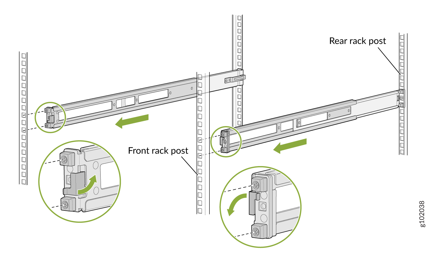
Move the latch lock on the front mounting rails to open position, slide the front
mounting rails, and insert the guide blocks into the front rack posts. See Figure 4.
Figure 4: Install the Front Mounting Rails
-
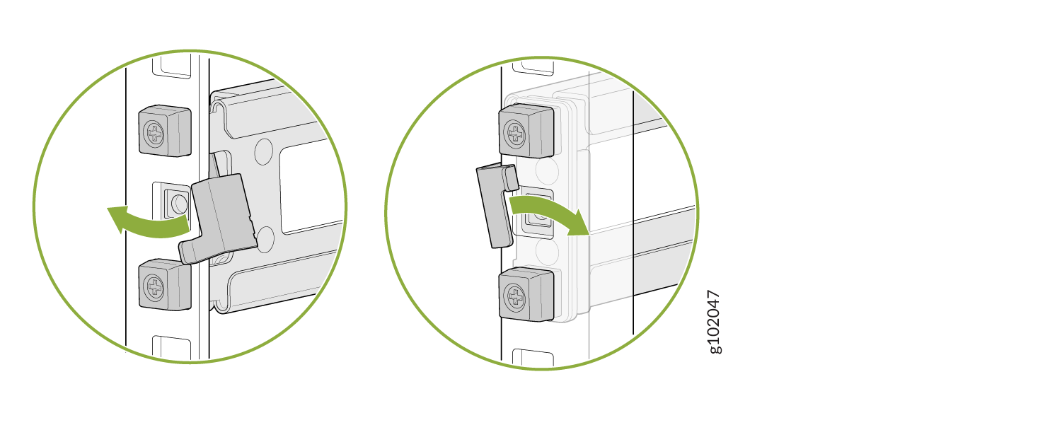
Push the lock latch to the locked position. See Figure 5.
Figure 5: Front Mounting Rails Lock Latch
-
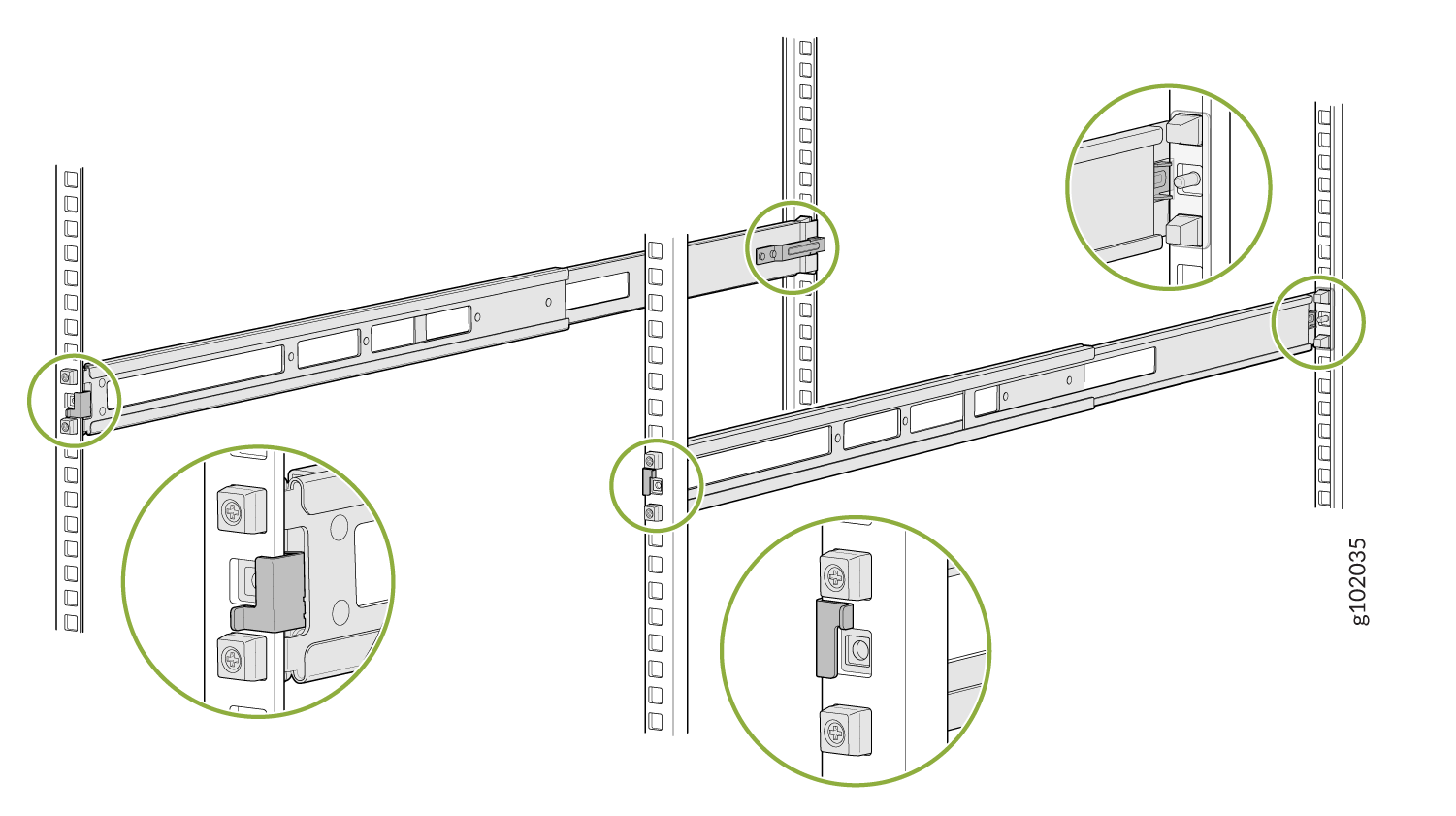
Visually ensure that the front and rear latches are locked into place on the
mounting rails. See Figure 6.
Figure 6: Mounting Rails Installed and Locked
-
Align the guide blocks of the rear mounting rails with the rear-post holes. Pull
the rear mounting rails toward the front of the rack to lock the rails in place. You
will hear a click sound when the latch locks into the corresponding rack holes. See
Figure 3.
-
Attach mounting brackets to the device if not pre-installed. If your device already has
the mounting brackets pre-installed than skip this step and move to the next step.
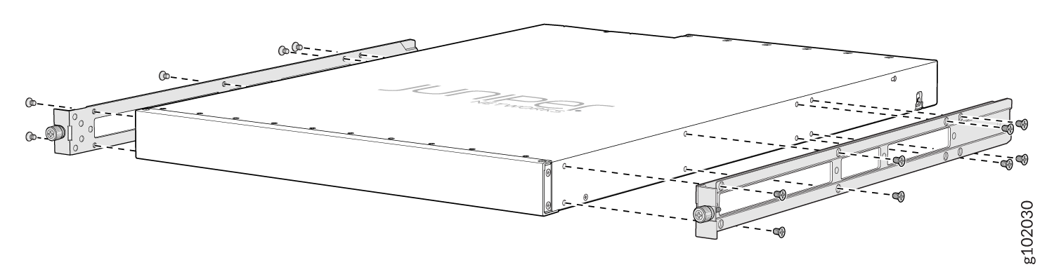
-
Insert the flat head M4 x 6mm Phillips screws to attach the mounting bracket into
the aligned holes on the chassis (see Figure 7). Tighten the screws.
Figure 7: Attach the Mounting Brackets to the Device
-
Insert the flat head M4 x 6mm Phillips screws to attach the mounting bracket into
the aligned holes on the chassis (see Figure 7). Tighten the screws.
-
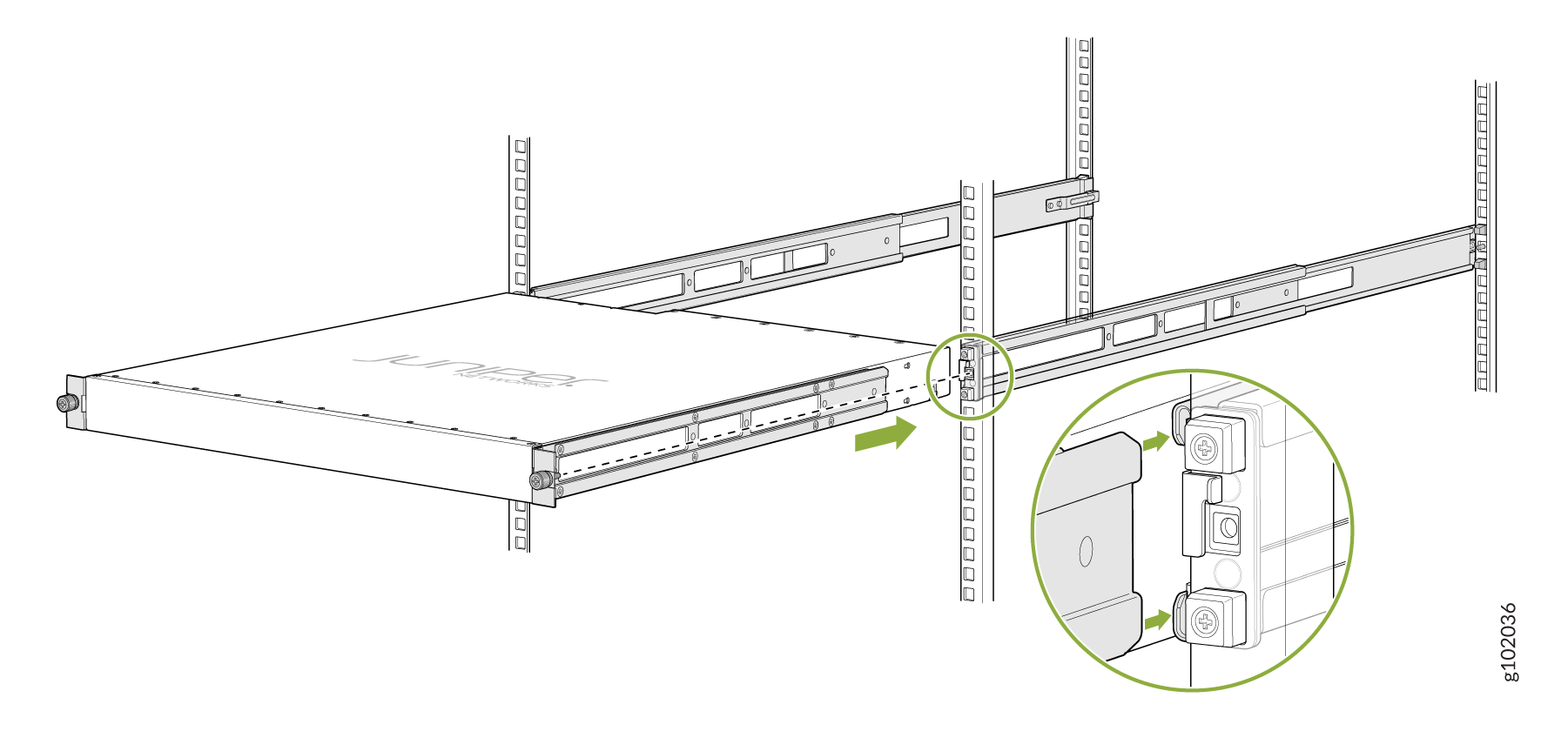
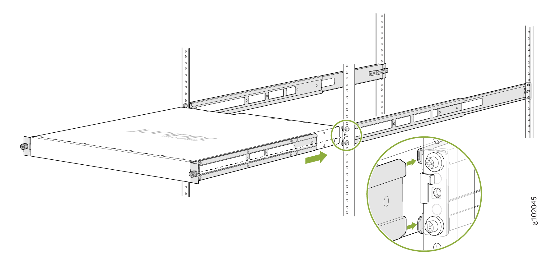
Grasp both sides of the device, lift it, and position the device such that the mounting
rails slide into the channels of the mounting brackets. See Figure 8.
Figure 8: Slide the Device into the Rack
-
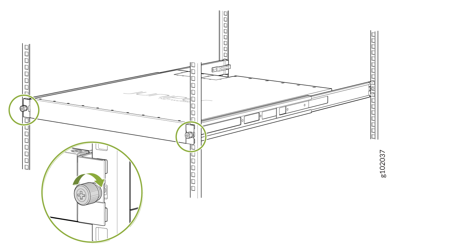
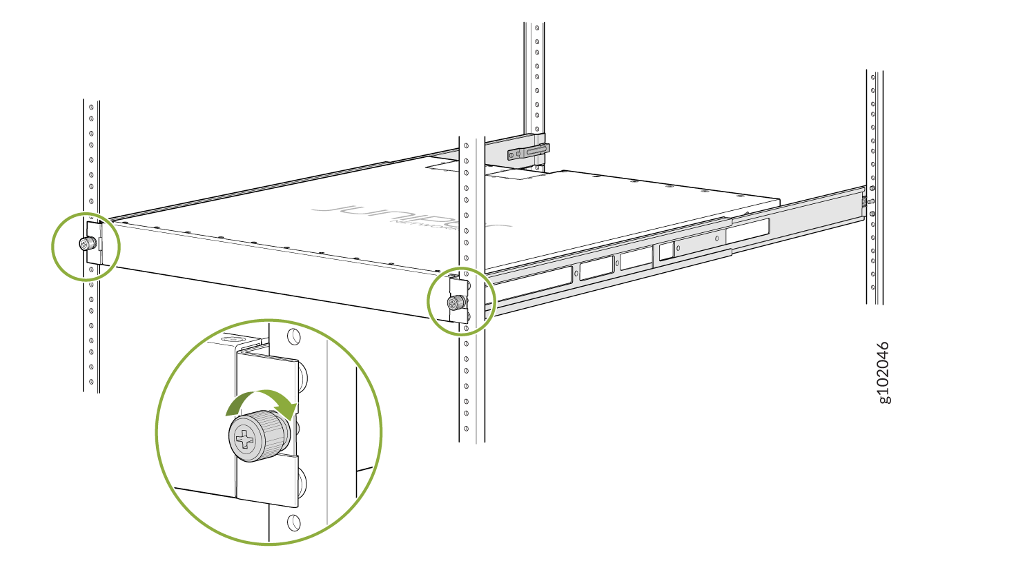
Tighten the two thumbscrews to secure the device. See Figure 9.
Figure 9: Tighten the Thumb Screws
Mount the Device by Using the JNP-4PST-RMK-1U-E Rack Mount Kit On a Threaded Hole Rack
Ensure that you have the following tools and parts available:
-
An ESD grounding strap—not provided
-
Number 2 Phillips (+) screwdriver—not provided
-
A pair of front and rear mounting rails that attach to the rack posts—provided with the rack mount kit
-
A pair of side mounting brackets and 16 flat head M4 x 6mm Phillips screws. These brackets attach to the device if not pre-installed—provided with the rack mount kit
To mount the device on four posts in a threaded hole rack by using the JNP-4PST-RMK-1U-E rack mount kit:
-
Assemble the mounting rails.
-
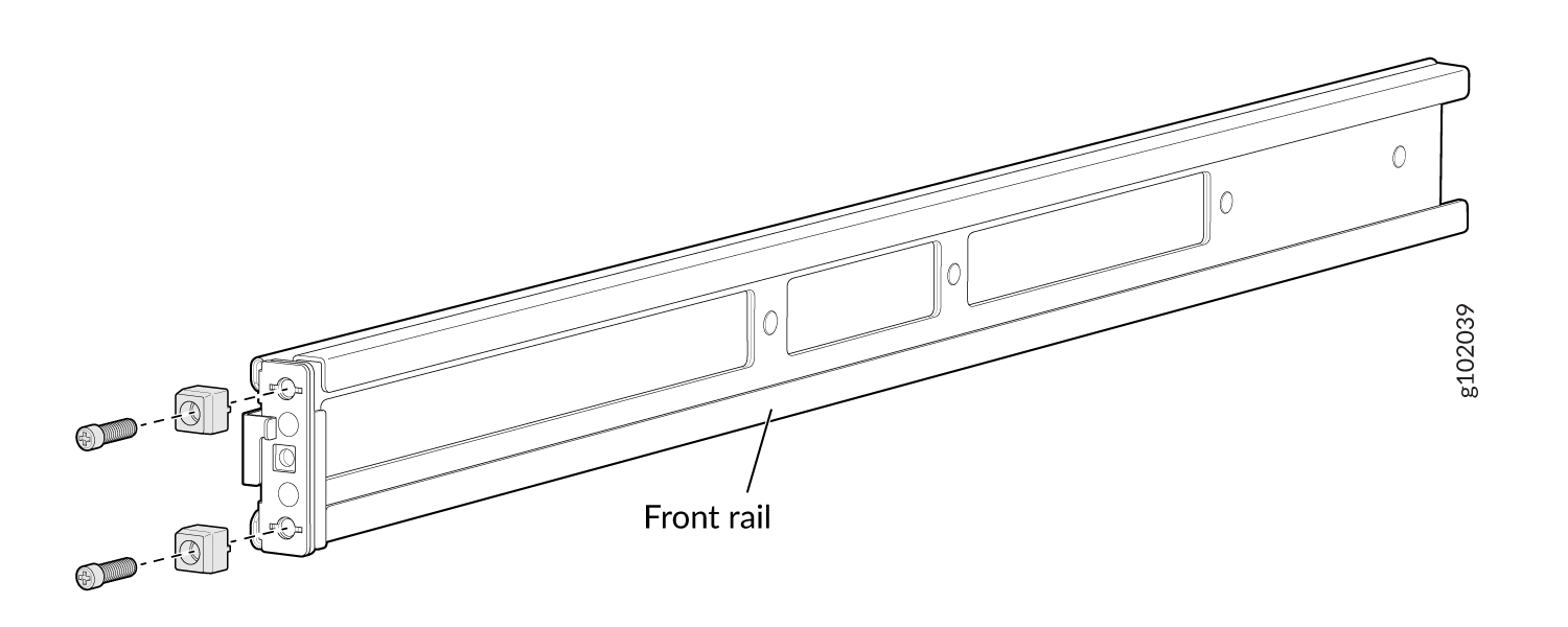
Remove the guide blocks from the front mounting rails by loosening the screws and
preserve them for later use. See Figure 10.
Figure 10: Remove Guide Blocks from Front Mounting Rail
-
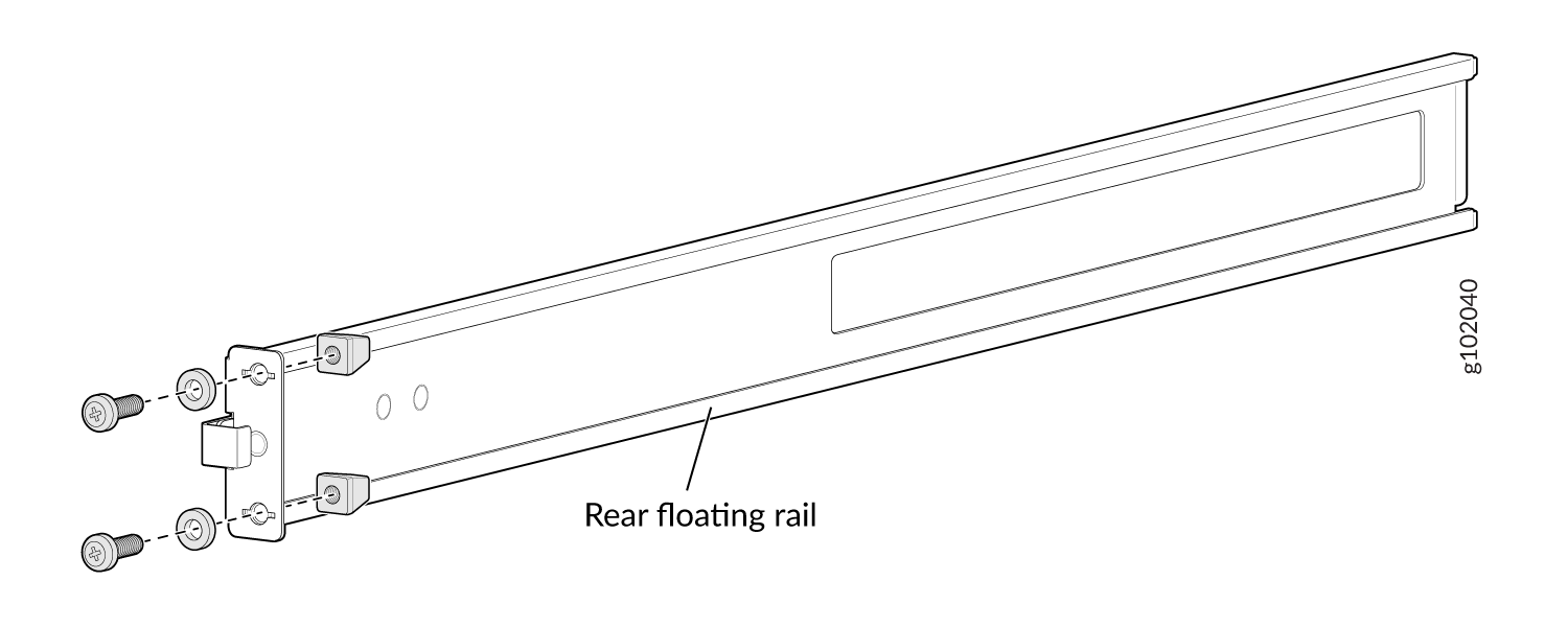
Remove the guide blocks from the rear floating rails by loosening the screws and
washers. Preserve the guide blocks, screws, and washers for later use. See Figure 11
Figure 11: Remove Guide Blocks from Rear Floating Rail
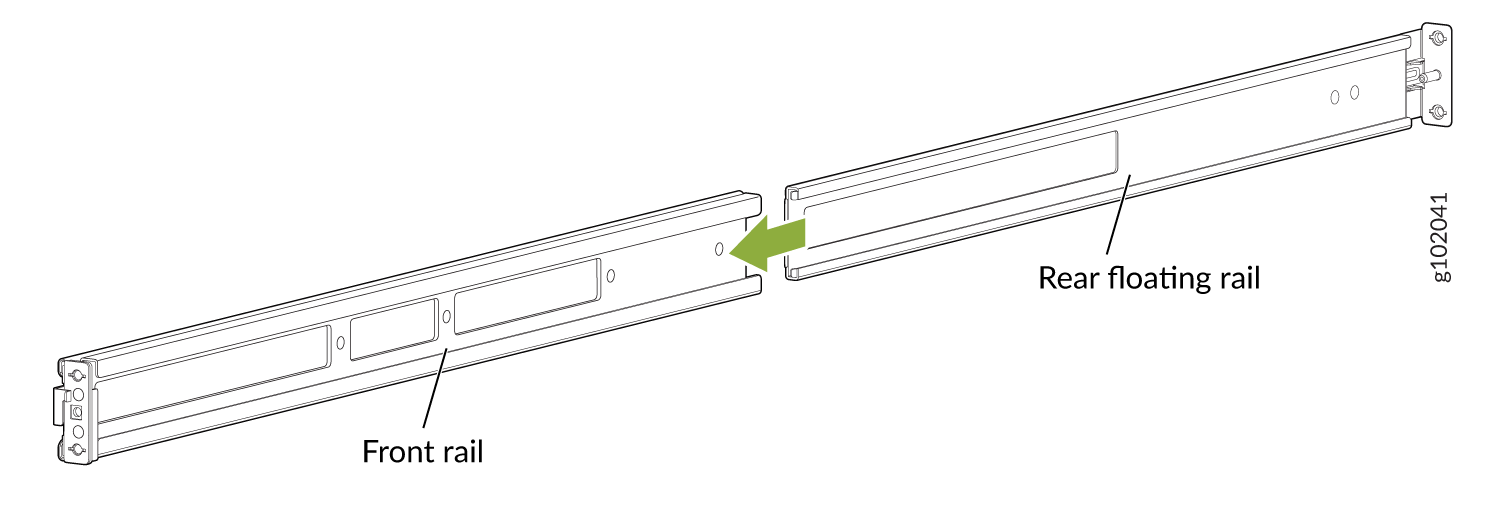
-
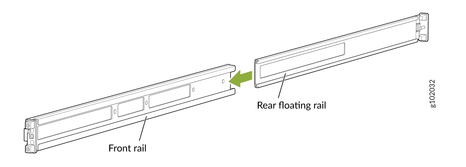
Slide the rear floating rails into the front mounting rails. See Figure 12.
Figure 12: Slide Rear Floating Rail into Front Mounting Rail
-
Mounting rails assembled. See Figure 13.
Figure 13: Front and Rear Rails Assembled
-
Remove the guide blocks from the front mounting rails by loosening the screws and
preserve them for later use. See Figure 10.
-
Attach the mounting rails to the threaded hole rack.
-
Align the guide blocks of the rear mounting rails with the rear-post holes. Pull
the rear mounting rails toward the front of the rack to lock the rails in place. You
will hear a click sound when the latch locks into the corresponding rack holes. See
Figure 14.
Figure 14: Install the Rear Floating Rails
-
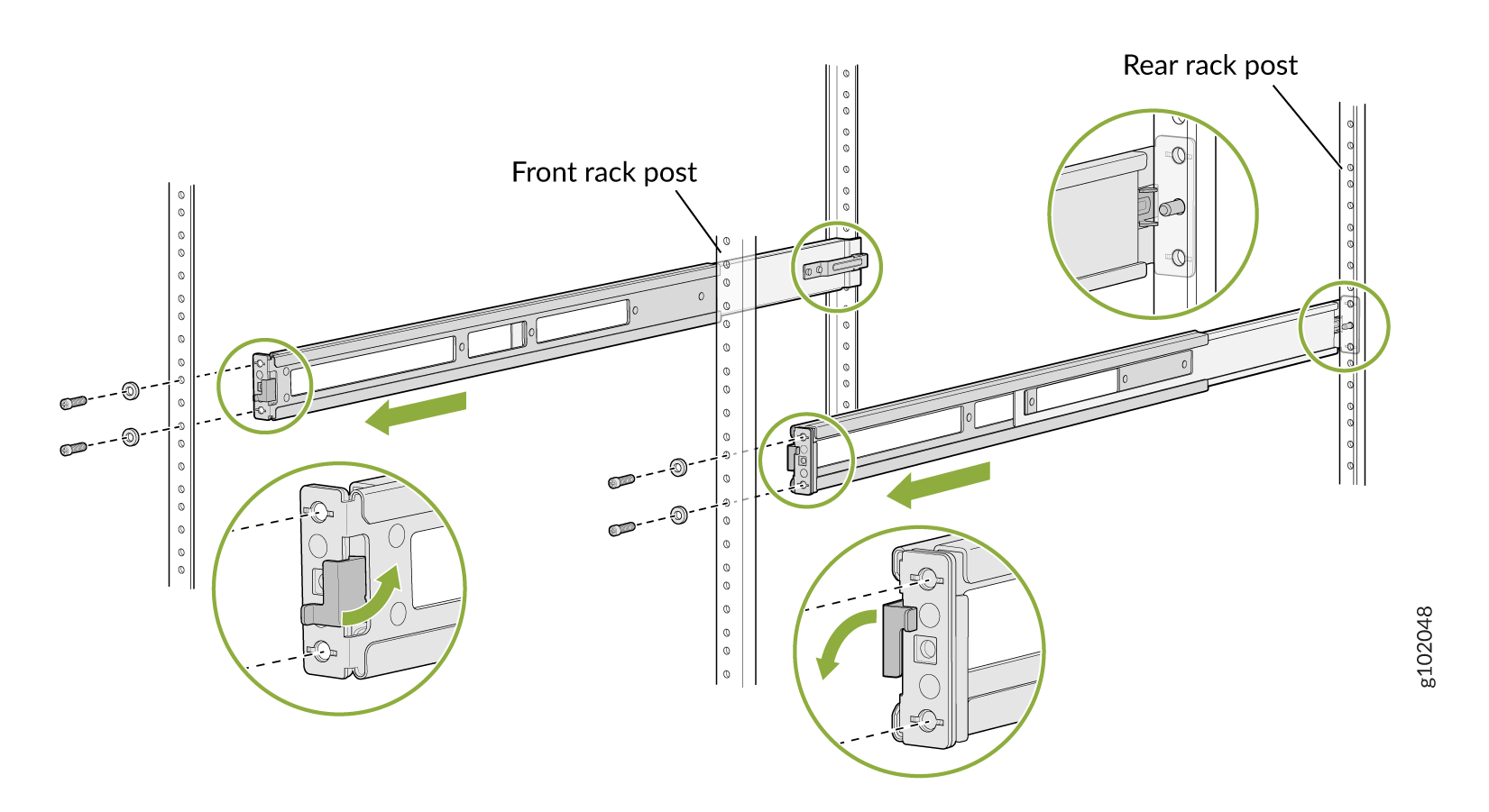
Move the latch locks on the front mounting rails to open position, slide the front
mounting rails and align them to the front rack post. Push the lock latch to locked
position and using the screws removed in step 2.a and
the washers removed in step 2.b,
secure the front mounting rails to the front rack post. See Figure 15.
Figure 15: Install the Front Mounting Rails
-
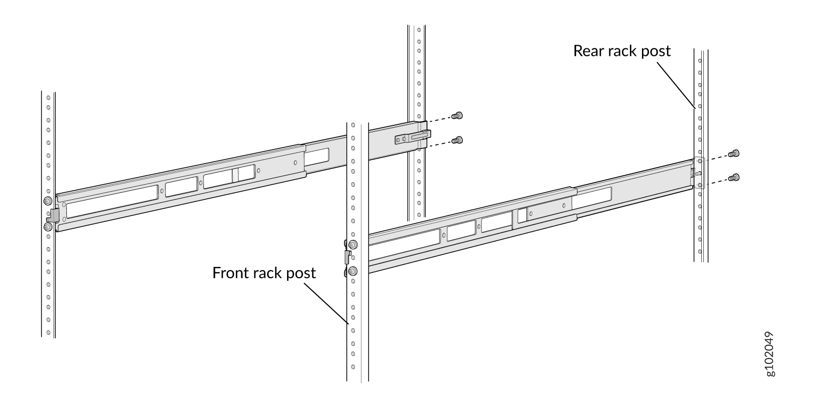
Secure the rear floating rails to the rear rack post by using screws (not provided)
appropriate for your rack threaded size. See Figure 16.
Figure 16: Secure the Rear Floating Rails
-
Visually ensure that the front and rear latches are locked into place on the
mounting rails. See Figure 17.
Figure 17: Mounting Rails Installed and Secured
-
Align the guide blocks of the rear mounting rails with the rear-post holes. Pull
the rear mounting rails toward the front of the rack to lock the rails in place. You
will hear a click sound when the latch locks into the corresponding rack holes. See
Figure 14.
-
Attach mounting brackets to the device if not pre-installed. If your device already has
the mounting brackets pre-installed than skip this step and move to the next step.
-
Insert the flat head M4 x 6mm Phillips screws to attach the mounting bracket into
the aligned holes on the chassis (see Figure 18). Tighten the screws.
Figure 18: Attach the Mounting Brackets to the Device
-
Insert the flat head M4 x 6mm Phillips screws to attach the mounting bracket into
the aligned holes on the chassis (see Figure 18). Tighten the screws.
-
Grasp both sides of the device, lift it, and position the device such that the mounting
rails slide into the channels of the mounting brackets. See Figure 19.
Figure 19: Slide the Device into the Rack
-
Tighten the two thumbscrews to secure the device. See Figure 20.
Figure 20: Tighten Thumb Screws
Mount an EX4650-48Y switch on a Two-Post Rack using the EX-RMK Rack Mount Kit
Before you mount an EX4650-48Y switch on a two-post rack:
-
Verify that the site meets the requirements.
-
Place the rack in its permanent location, allowing adequate clearance for airflow and maintenance, and secure the rack to the building structure.
-
Read General Safety Guidelines and Warnings, with particular attention to Chassis and Component Lifting Guidelines.
-
Ensure that you have taken the necessary precautions to prevent electrostatic discharge (ESD) damage (see Prevention of Electrostatic Discharge Damage).
-
Remove the switch from the shipping carton.
Ensure that you have the following parts and tools available:
-
Number 2 Phillips (+) screwdriver—not provided
-
Eight screws to secure the mounting brackets to the rack—not provided
-
Electrostatic discharge (ESD) grounding strap—not provided
-
Two-post rack mounting bracket for mounting the switch on a two-post rack—2 (provided with the two-post rack mount kit)
-
Flat head 4x6-mm Phillips screws for attaching the two-post rack mounting brackets to the chassis—8 (provided with the two-post rack mount kit)
You can mount EX4650-48Y switches on a two-post rack by using a separately orderable two-post rack mount kit (EX-RMK). This topic describes the procedure to mount an EX4650-48Y switch on a two-post rack.
One person must be available to lift the switch while another person secures the switch to the rack.
If you are mounting multiple units on a rack, mount the heaviest unit at the bottom of the rack, and then mount the other units from the bottom of the rack to the top in decreasing order of the weight of the units.
To mount an EX4650-48Y switch on a two-post rack:
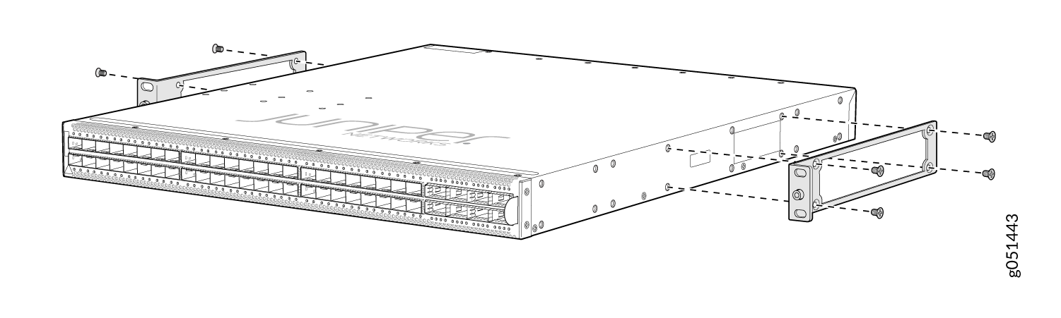
-
Insert the flat head 4x6-mm Phillips screws for attaching the two-post rack
mounting brackets (provided with the two-post rack mount kit) into the
aligned holes on the chassis. Tighten the screws.
Figure 21: Attach the Two-Post Rack Mounting Brackets to an EX4650-48Y Switch Chassis
-
Have a second person secure the switch to the rack by using the screws
appropriate for your rack. Tighten the screws.
Figure 22: Secure the EX4650-48Y Switch to the Two-Post Rack
Your switch is now installed on a two-post rack.
Mounting an EX4650 Switch on Four Posts of a Rack or Cabinet Using the EX-4PST-RMK Rack Mount Kit
Before mounting the switch on four posts of a rack:
Verify that the site meets the requirements described in Site Preparation Checklist for EX4650 Switches
Place the rack in its permanent location, allowing adequate clearance for airflow and maintenance, and secure it to the building structure.
Read General Safety Guidelines and Warnings, with particular attention to Chassis and Component Lifting Guidelines.
Remove the switch from the shipping carton (seeUnpacking the Switch.
Ensure that you have the following parts and tools available:
Phillips (+) screwdriver, number 2 (not provided)
6 flat-head 4-40 Phillips mounting screws (provided with the four-post rack-mount kit)
12 flat-head 4x6-mm Phillips mounting screws (provided with the four-post rack-mount kit)
One pair each of flush or 2-in.-recess front-mounting brackets (provided with the four-post rack-mount kit)
One pair of side mounting-rails (provided with the four-post rack-mount kit)
One pair of rear mounting-blades (provided with the four-post rack-mount kit)
Screws to secure the chassis and the rear mounting-blades to the rack (not provided)
You can mount an EX4650 switch on four posts of a 19-in. rack or a 19-in. cabinet by using the separately orderable four-post rack-mount kit. (The remainder of this topic uses rack to mean rack or cabinet.)
To ensure that the protective earthing terminal is accessible through the opening in the rear mounting-blade:
Ensure that the rack is 27.5 in. (70 cm) through 30.5 in. (77.5 cm) deep if you are mounting the switch flush with the rack front on four posts of a rack.
Ensure that the rack is 29.5 in. (75 cm) through 32.5 in. (82.5 cm) deep if you are mounting the switch 2 in. recessed from the rack front.
One person must be available to lift the switch while another secures it to the rack.
If you are mounting multiple units on a rack, mount the heaviest unit at the bottom of the rack and mount the other units from the bottom of the rack to the top in decreasing order of the weight of the units.
To mount the switch on four posts of a rack:
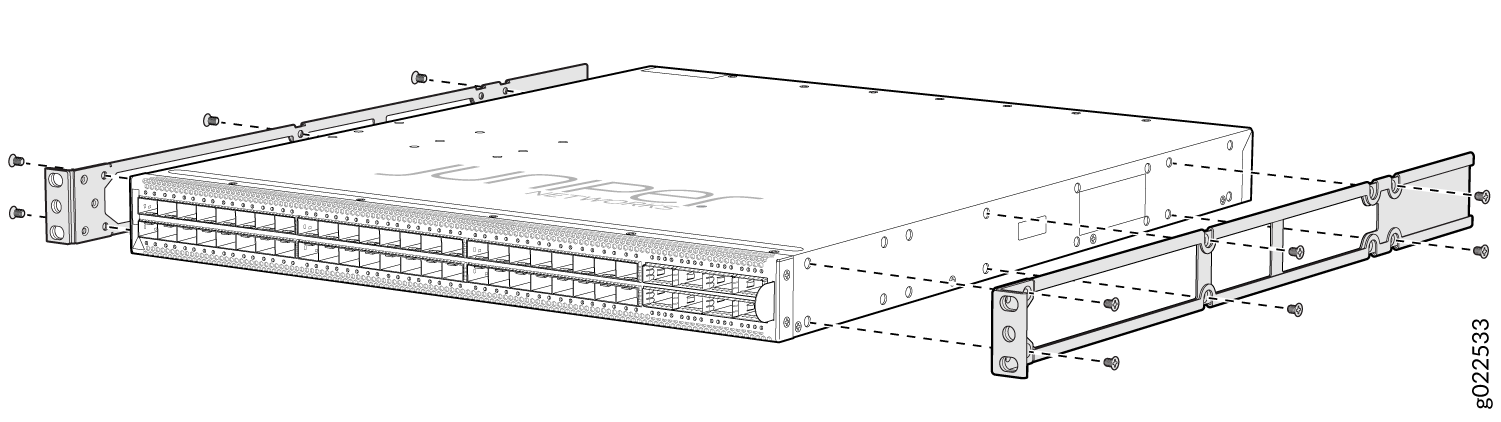
- Insert 4x6-mm Phillips flat-head mounting screws into
the two aligned holes and tighten the screws by using the screwdriver.
Ensure that the remaining four holes in the side mounting-rails are
aligned with the four holes in the side panel. See Figure 23.Figure 23: Attaching the Side Mounting-Rail to the Switch Chassis
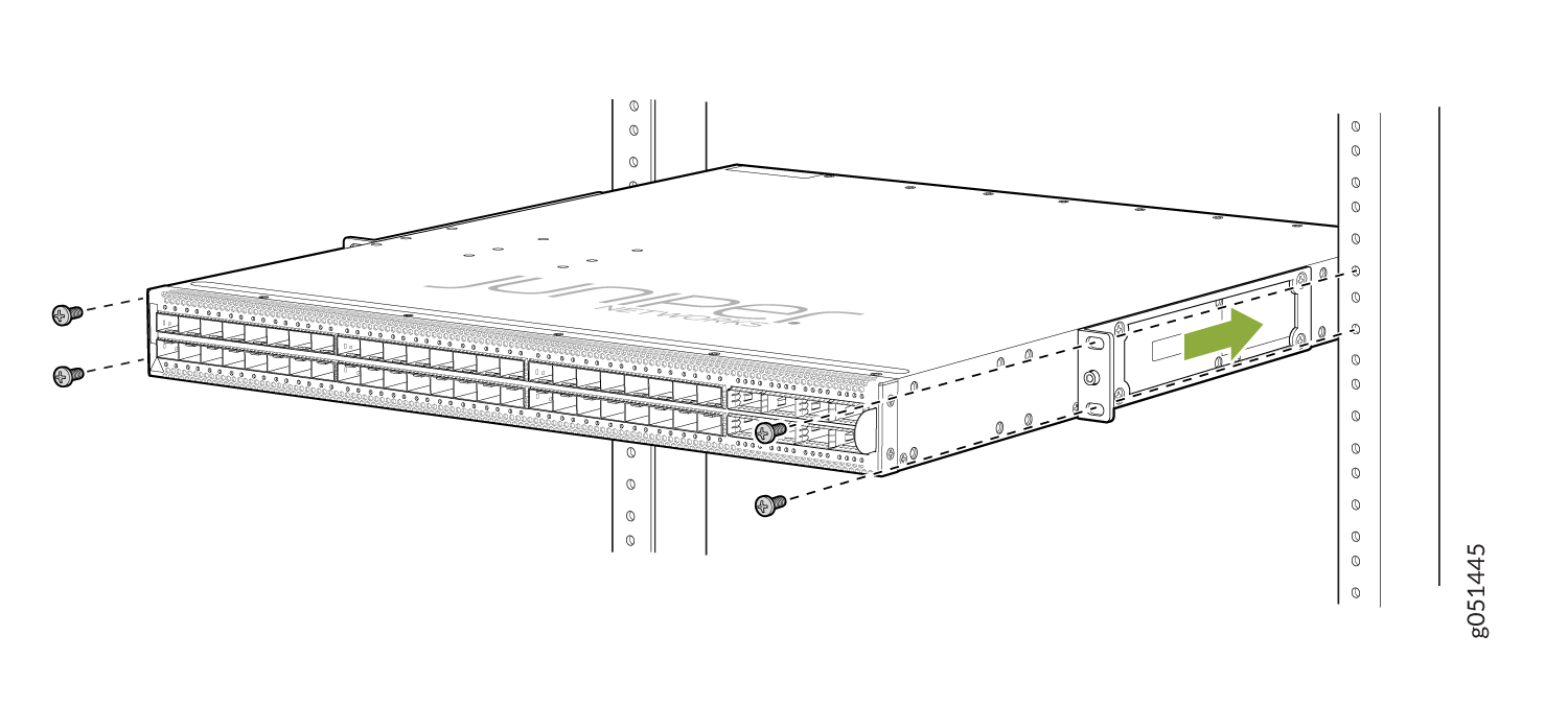
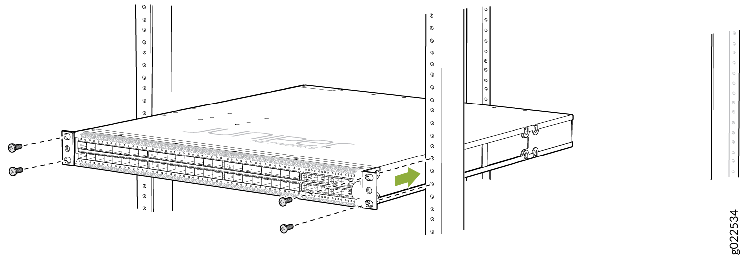
- Have one person grasp both sides of the switch, lift the
switch, and position it in the rack, aligning the side mounting-rail
holes with the threaded holes in the front post of the rack. Align
the bottom hole in both the front-mounting brackets with a hole in
each rack rail, making sure the chassis is level. See Figure 24.Figure 24: Mounting the Switch on Front Posts of a Rack
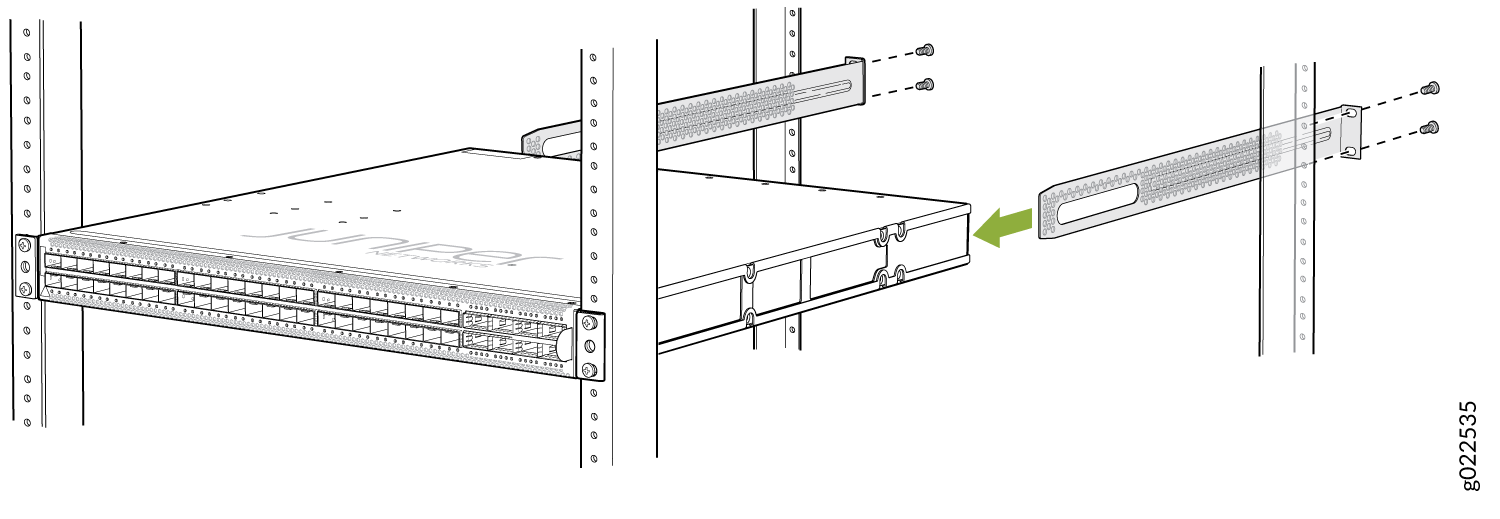
- Slide the rear mounting-blades into the side mounting-rails.
See Figure 25.Figure 25: Sliding the Rear Mounting-Blades into the Side Mounting-Rails
We recommend that you install cover panels in the unused power supply slots.