ON THIS PAGE
Fast Track to Rack Installation and Power
This procedure guides you through the simplest steps for the most common installation to get your EX4650 switch in a rack and connect it to power. Have more complex installation needs? See Unpacking and Mounting the EX4650 Switch.
Install the EX4650 in a Rack
We’ll walk you through the steps to install an AC-powered switch in a four-post rack.
Before you install, review the following:
-
Verify that the site meets the requirements described in Site Preparation Checklist for EX4650 Switches.
-
Place the rack in its permanent location, allowing adequate clearance for airflow and maintenance, and secure it to the building structure.
-
Read General Safety Guidelines and Warnings, with particular attention to Chassis and Component Lifting Guidelines.
-
Remove the switch from the shipping carton (see Unpacking the Switch).
Ensure that you have the following parts and tools available:
-
Phillips (+) screwdriver, number 2 (not provided).
-
6 flat-head 4-40 Phillips mounting screws (provided with the four-post rack-mount kit).
-
12 flat-head 4x6-mm Phillips mounting screws (provided with the four-post rack-mount kit).
-
One pair each of flush or 2-in.-recess front-mounting brackets (provided with the four-post rack-mount kit).
-
One pair of side mounting-rails (provided with the four-post rack-mount kit).
-
One pair of rear mounting-blades (provided with the four-post rack-mount kit).
-
Screws to secure the chassis and the rear mounting-blades to the rack (not provided).
You can mount an EX4650 switch on four posts of a 19-in. rack or a 19-in. cabinet by using the separately orderable four-post rack-mount kit. (The remainder of this topic uses rack to mean rack or cabinet.)
To ensure that the protective earthing terminal is accessible through the opening in the rear mounting-blade:
-
Ensure that the rack is 27.5 in. (70 cm) through 30.5 in. (77.5 cm) deep if you are mounting the switch flush with the rack front on four posts of a rack.
-
Ensure that the rack is 29.5 in. (75 cm) through 32.5 in. (82.5 cm) deep if you are mounting the switch 2 in. recessed from the rack front.
One person must be available to lift the switch while another secures it to the rack.
If you are mounting multiple units on a rack, mount the heaviest unit at the bottom of the rack and mount the other units from the bottom of the rack to the top in decreasing order of the weight of the units.
To mount the switch on four posts of a rack:
Place the switch on a flat, stable surface.
Note:The four-post rack-mount kit ships with the short front-mounting brackets attached to the side mounting-rails. If you want to recess the switch in the rack, you must unscrew the short front-mounting brackets from the side mounting-rails by using the Phillips (+) screwdriver and attach the long front-mounting brackets to the side mounting-rails.
Align the side mounting-rails along the side panels of the switch chassis. Align the two holes in the rear of the side mounting-rails with the two holes on the rear of the side panels.
Insert 4x6-mm Phillips flat-head mounting screws into the two aligned holes and tighten the screws by using the screwdriver. Ensure that the remaining four holes in the side mounting-rails are aligned with the four holes in the side panel. See Figure 1
Figure 1: Attaching the Side Mounting-Rail to the Switch Chassis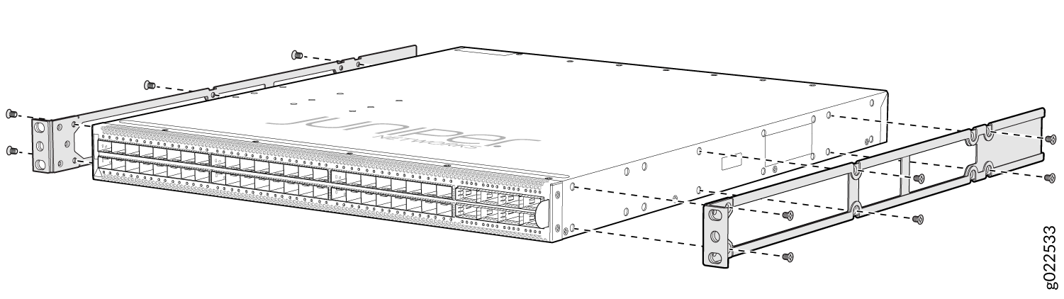
Insert the 4x6-mm Phillips flat-head mounting screws into the remaining four holes in the side mounting-rails and tighten the screws by using the screwdriver.
Have one person grasp both sides of the switch, lift the switch, and position it in the rack, aligning the side mounting-rail holes with the threaded holes in the front post of the rack. Align the bottom hole in both the front-mounting brackets with a hole in each rack rail, making sure the chassis is level. See Figure 2.
Figure 2: Sliding the Rear Mounting-Blades into the Side Mounting-Rails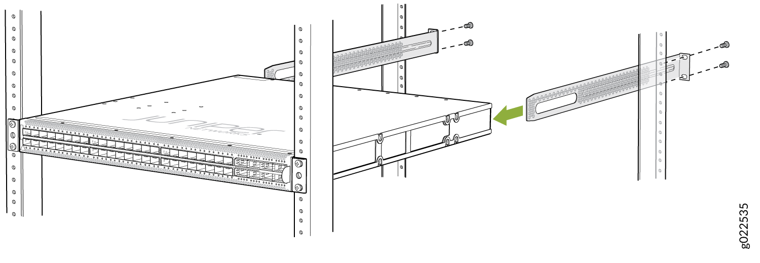
Have a second person secure the front of the switch to the rack by using the appropriate screws for your rack.
Slide the rear mounting-blades into the side mounting-rails. See Figure 2.
Attach the rear mounting-blades to the rear post by using the appropriate screws for your rack. Tighten the screws.
Ensure that the switch chassis is level by verifying that all the screws on the front of the rack are aligned with the screws at the back of the rack.
We recommend that you install cover panels in the unused power supply slots.
Connect to Power
To connect the EX4650 switch to AC power, you must do the following:
Ground the EX4650 Switch
To ground the EX4650 switch, do the following:
Connect one end of the grounding cable to a proper earth ground, such as the rack in which the switch is mounted.
Place the grounding lug attached to the grounding cable over the protective earthing terminal. The protective earthing terminal is located on the left panel (see Figure 3.)
Figure 3: Connect a Grounding Cable to the EX4650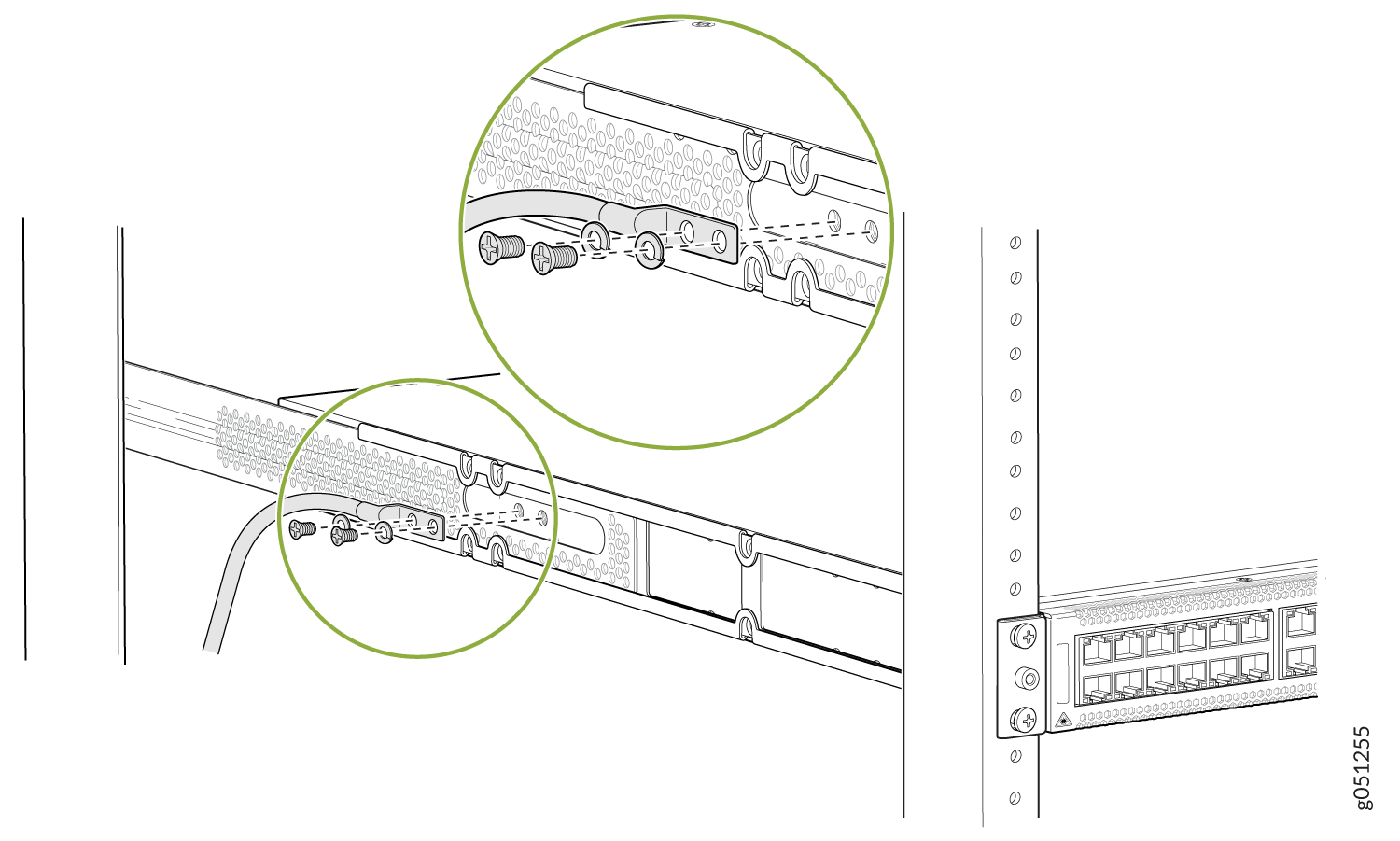
Secure the grounding lug to the protective earthing terminal with the screws.
Dress the grounding cable and ensure that it does not touch or block access to other switch components.
Warning:Ensure that the cable does not drape where people could trip over it.
Connect the Power Cord and Power On the Switch
For information about the supported AC power cord specifications, see AC Power Cord Specifications for EX4650 Switches.
To connect the power cord, do the following:
Attach the grounding strap to your bare wrist and to a site ESD point.
Ensure that the power supplies are fully inserted in the chassis and the latches are secure. If only one power supply is installed, ensure that a blank cover panel is installed over the second power supply slot.
Locate the power cord or cords shipped with the switch; the cords have plugs appropriate for your geographical location.
Warning:Ensure that the power cord does not block access to device components or drape where people can trip on it.
Connect each power supply to the power sources. Insert the coupler end of the power cord into the AC power cord inlet on the AC power supply faceplate.
Push the power cord retainer onto the power cord (see Figure 4).
Figure 4: Connecting an AC Power Cord to an AC Power Supply in an EX4650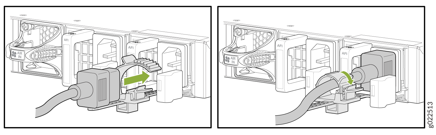
The switch powers on as soon as power is provided to the power supply. There is no power switch on the device.
Insert the power cord plug into an AC power source outlet.
Verify that the AC and DC LEDs on each power supply are lit green.
If the amber fault LED is lit, remove power from the power supply, and replace the power supply. Do not remove the power supply until you have a replacement power supply ready: the power supplies or a blank cover panel must be installed in the switch to ensure proper airflow.
CAUTION:Replace a failed power supply with a blank panel or new power supply within one minute of removal to prevent chassis overheating.