ON THIS PAGE
EX4650 Power System
AC Power Supply in EX4650 Switches
EX4650 switches support two AC or DC power supplies with different airflow directions. Power supplies for the EX4650 switch are fully redundant, load-sharing, and hot-removable and hot-insertable FRUs. The EX4650 switch models are shipped with two power supplies pre-installed in the rear panel of the chassis.
- AC Power Supply in EX4650 Switches
- DC Power Supply in EX4650 Switches
- Airflow Direction in Power Supplies
AC Power Supply in EX4650 Switches
EX4650 switch supports two 650 W AC power supplies.
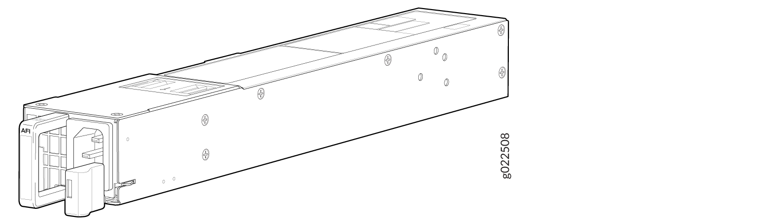
Figure 1 shows an AC power supply for an EX4650 switch.
DC Power Supply in EX4650 Switches
The DC power supply in EX4650 is 650 W with dual feeds for power resiliency. Figure 2 shows a DC power supply for an EX4650 switch.
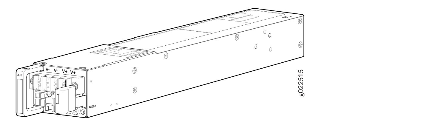
The DC power supply in the switch has four terminals labeled V-, V-, V+, and V+ for connecting DC power source cables labeled and negative (–) and positive (+). See Figure 3.
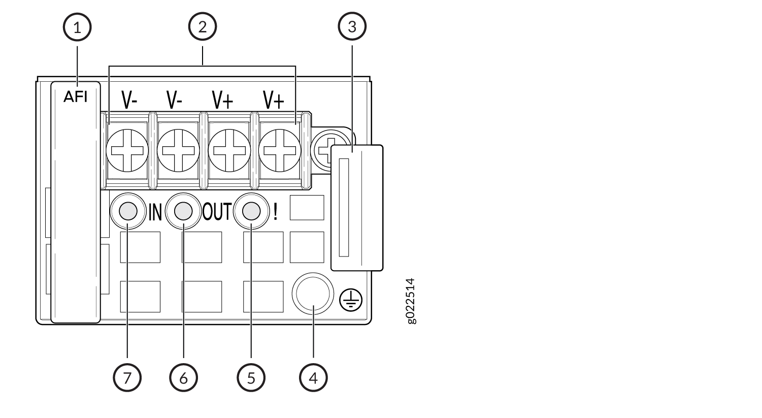
1 — AFI | 5 — Fault LED |
2 — Input terminals | 6 — Ouput LED |
3 — Ejector lever | 7 — Input LED |
4 — ESD grounding point |
Airflow Direction in Power Supplies
Each power supply has two fan supplies and is cooled by its own internal cooling system.
The power supplies either have labels on the handles that indicate the direction of airflow or they have color-coded handles with a fan icon. AFI label or a blue-colored handle indicates back-to-front airflow while AFO label or an orange-colored handle indicates front-to-back airflow. See Figure 4
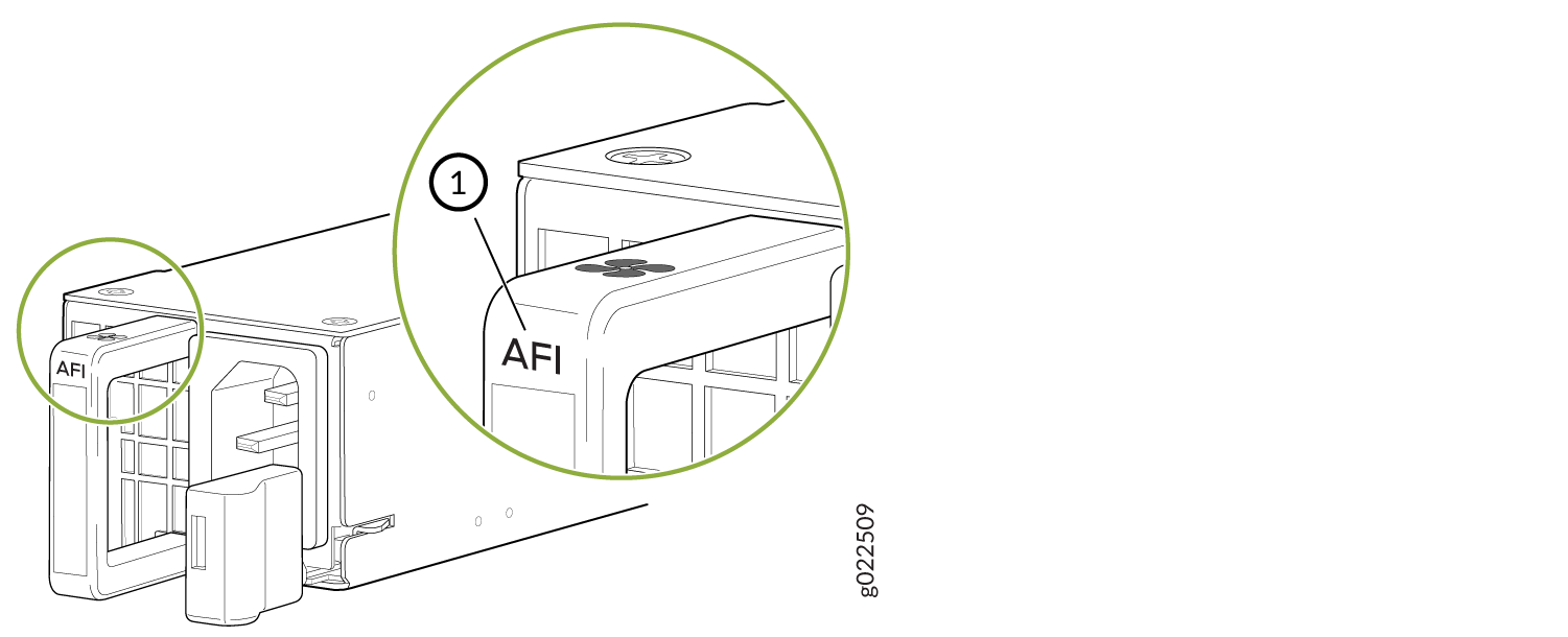
1 — AIR IN (AFI) label |
Be sure to use the correct power supply for your chassis product SKU (see Table 1).
Do not mix:
-
AC and DC power supplies in the same chassis.
-
Power supplies with different airflow labels (AFI and AFO) in the same chassis.
-
Power supplies and fan modules with different airflow labels (AFI and AFO) in the same chassis.
Verify that the airflow direction on the power supply handle matches the direction of airflow in the chassis. Ensure that each power supply you install in the chassis has the same airflow direction. If you install power supplies with two different airflow directions, Junos OS raises an alarm. If you need to convert the airflow pattern on a chassis, you must replace all the fans and power supplies at one time to use the new direction.
Table 1 lists the AC and DC power supplies used in EX4650 switches and the direction of airflow in them.
|
Product Number |
Direction of Airflow |
Color of Power Supply Handle |
|---|---|---|
|
EX4650-48Y-AFO |
Front to back |
Orange |
|
EX4650-48Y-AFI |
Back to front |
Blue |
|
EX4650-48Y-DC-AFO |
Front to back |
Orange |
|
EX4650-48Y-DC-AFI |
Back to front |
Blue |
AC Power Supply Specifications for EX4650 Switches
EX4650 switches support 650 W AC power supplies.
The table in this topic provides power supply specification of AC power supplies used in an EX4650 switch:
Item |
650 W AC Specification |
|---|---|
| Model Number |
|
AC input voltage |
Operating range: 100 VAC to 240 VAC |
AC input line frequency |
50–60 Hz |
AC input current rating |
7.8A at 100-120 VAC 3.8A at 200-240 VAC |
Typical Power Consumption |
260W |
Maximum power |
450W |
|
Efficiency |
80 plus platinum |
AC Power Cord Specifications for EX4650 Switches
A detachable AC power cord is supplied with the AC power supplies. The coupler is type C13 as described by International Electrotechnical Commission (IEC) standard 60320. The plug end of the power cord fits into the power source outlet that is standard for your geographical location.
The AC power cord provided with each power supply is intended for use with that power supply only and not for any other use.
In North America, AC power cords must not exceed 4.5 meters in length, to comply with National Electrical Code (NEC) Sections 400-8 (NFPA 75, 5-2.2) and 210-52 and Canadian Electrical Code (CEC) Section 4-010(3). The cords supplied with the switch are in compliance.
Table 3 gives the AC power cord specifications for the countries and regions listed in the table.
Country/Region |
Electrical Specifications |
Plug Standards |
Juniper Model Number |
|---|---|---|---|
Argentina |
250 VAC, 10 A, 50 Hz |
IRAM 2073 Type RA/3 |
CBL-EX-PWR-C13-AR |
Australia |
250 VAC, 10 A, 50 Hz |
AS/NZZS 3112 Type SAA/3 |
CBL-EX-PWR-C13-AU |
Brazil |
250 VAC, 10 A, 50 Hz |
NBR 14136 Type BR/3 |
CBL-EX-PWR-C13-BR |
China |
250 VAC, 10 A, 50 Hz |
GB 1002-1996 Type PRC/3 |
CBL-EX-PWR-C13-CH |
Europe (except Italy, Switzerland, and United Kingdom) |
250 VAC, 10 A, 50 Hz |
CEE (7) VII Type VIIG |
CBL-EX-PWR-C13-EU |
India |
250 VAC, 10 A, 50 Hz |
IS 1293 Type IND/3 |
CBL-EX-PWR-C13-IN |
Israel |
250 VAC, 10 A, 50 Hz |
SI 32/1971 Type IL/3G |
CBL-EX-PWR-C13-IL |
Italy |
250 VAC, 10 A, 50 Hz |
CEI 23-16 Type I/3G |
CBL-EX-PWR-C13-IT |
Japan |
125 VAC, 12 A, 50 Hz or 60 Hz |
JIS 8303 |
CBL-EX-PWR-C13-JP |
Korea |
250 VAC, 10 A, 50 Hz or 60 Hz |
CEE (7) VII Type VIIGK |
CBL-EX-PWR-C13-KR |
North America |
125 VAC, 13 A, 60 Hz |
NEMA 5-15 Type N5-15 |
CBL-EX-PWR-C13-US |
South Africa |
250 VAC, 10 A, 50 Hz |
SABS 164/1:1992 Type ZA/13 |
CBL-EX-PWR-C13-SA |
Switzerland |
250 VAC, 10 A, 50 Hz |
SEV 6534-2 Type 12G |
CBL-EX-PWR-C13-SZ |
Taiwan |
125 VAC, 11 A and 15 A, 50 Hz |
NEMA 5-15P Type N5-15P |
CBL-EX-PWR-C13-TW |
United Kingdom |
250 VAC, 10 A, 50 Hz |
BS 1363/A Type BS89/13 |
CBL-EX-PWR-C13-UK |
Figure 5 illustrates the plug on the power cord for some of the countries or regions listed in Table 3.
AC Power Supply LEDs in EX4650 Switches
Figure 6 shows the location of the LEDs on an AC power supply for EX4650 switches.
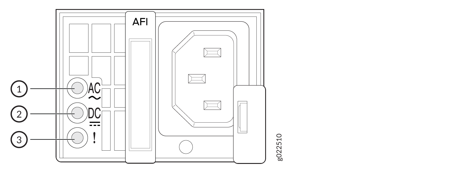
1 — AC OK | 3 — Fault |
2 — DC OK |
Table 4 describes the AC power supply LEDs.
LED |
Color |
State |
Description |
|---|---|---|---|
AC OK |
Unlit |
Off |
The power supply is disconnected from power, or power is not coming into the power supply. |
Green |
On steadily |
Power is coming into the power supply. |
|
DC OK |
Unlit |
Off |
The power supply is disconnected from power, or power is not coming into the power supply. |
Green |
On steadily |
The power supply is sending out power correctly. |
|
Fault |
Amber |
On steadily |
An error has been detected in the power supply. Replace the power supply as soon as possible. To maintain proper airflow through the chassis, leave the power supply installed in the chassis until you are ready to replace it. |
If the AC OK LED and the AC OK LED are not lit green, either the AC power cord is not installed properly or the power input voltage is not within normal operating range.
If the AC OK LED is lit green and the AC OK LED is unlit or lit red, the AC power supply is installed properly, but the power supply has an internal failure.
DC Power Supply in EX4650 Switches
The DC power supply in EX4650 switches is a hot-insertable and hot-removable field-replaceable unit (FRU): You can install it without powering off the switch or disrupting the switching function.
All the EX4650 switches that are powered by DC power supplies are shipped with one DC power supply pre-installed in the rear panel of the switches.
Do not mix:
AC and DC power supplies in the same chassis
Power supplies with different airflow labels (AIR IN (AFI) and AIR OUT (AFO)) in the same chassis.
Fan modules with different airflow labels (AIR IN (AFI) and AIR OUT (AFO)) in the same chassis.
Power supplies and fan modules with different airflow labels (AIR IN (AFI) and AIR OUT (AFO)) in the same chassis.
This topic includes:
Characteristics of a DC Power Supply
EX4650 switches support 650 W DC power supply (see Figure 7).
You can install up to two DC power supplies in an EX4650 switch. Power supplies are installed in the power supply slots labeled PSU 0 and PSU 1 in the rear panel of the chassis.
Table 5 lists the details of the 650 W DC power supplies used in EX4650 switches.
Details |
650 W DC Power Supply |
|
|---|---|---|
Model number |
|
|
Field-replaceable unit (FRU) type |
Hot-insertable and hot-removable |
|
Power supply weight |
2.43 lb (1.1 kg) |
|
Minimum installed in chassis |
1 |
|
Maximum installed in chassis |
2 |
|
Power supply slots |
Install in power supply slots labeled PSU 0 and PSU 1 in the rear panel of the chassis. |
|
Fans |
Internal |
|
Airflow |
|
|
Power supply status LEDs |
AC OK and DC OK |
|
DC input current rating |
4 A |
|
Operating range |
–38 through –60 VDC Note:
The minimum input power required to power on the switch is –43.5 +/– 0.5 VDC. After the switch is powered on, the operating range is –38 through –60 VDC. |
|
DC Power Supply Airflow
Each power supply has its own fan and is cooled by its own internal cooling system.
Each power supply has a label AIR OUT (AFO) or AIR IN (AFI) on the faceplate of the power supply that indicates the direction of airflow in the power supply.
Table 6 lists the DC power supply models and the direction of airflow in them.
Model |
Label on Power Supply |
Direction of Airflow |
|---|---|---|
| JPSU-650W-DC-AFO | AIR OUT (AFO) |
Front-to-back—that is, air intake to cool the chassis is through the vents on the front panel of the chassis and hot air exhausts through the vents on the rear panel of the chassis. |
| JPSU-650W-DC-AFI | AIR IN (AFI) |
Back-to-front—that is, air intake to cool the chassis is through the vents on the rear panel of the chassis and hot air exhausts through the vents on the front panel of the chassis. |
DC Power Supply in EX4650 Switches
EX4650 switches support two DC power supplies with either front-to back or back-to-front airflow. Power supplies for the EX4650 switch are fully redundant, load-sharing, and hot-removable and hot-insertable FRUs. The EX4650 switch models are shipped with two power supplies preinstalled in the rear panel of the chassis.
DC Power Supply in EX4650 Switches
The DC power supply in EX4650 is 650 W with dual feeds for power resiliency. Figure 8 shows a DC power supply for an EX4650 switch.
The DC power supply in the switch has four terminals labeled V-, V-, V+, and V+ for connecting DC power source cables labeled positive (+) and negative (–) as shown in Figure 9.
1 — AFI | 5 — Fault LED |
2 — Input terminals | 6 — Ouput LED |
3 — Ejector lever | 7 — Input LED |
4 — ESD grounding point |
Airflow Direction in Power Supplies
Each power supply has two fan supplies and is cooled by its own internal cooling system.
The power supplies either have labels on the handles that indicate the direction of airflow or they have color-coded handles with a fan icon. AIR IN (AFI) label or a blue-colored handle indicates back-to-front airflow while AIR OUT (AFO) label or an orange-colored handle indicates front-to-back airflow. See Figure 10
1 — AIR IN (AFI) label |
Be sure to use the correct power supply for your chassis product SKU (see Table 7).
Do not mix:
-
AC and DC power supplies in the same chassis.
-
Power supplies with different airflow labels (AIR IN (AFI) and AIR OUT (AFO)) in the same chassis.
-
Power supplies and fan modules with different airflow labels (AIR IN (AFI) and AIR OUT (AFO)) in the same chassis.
Verify that the airflow direction on the power supply handle matches the direction of airflow in the chassis. Ensure that each power supply you install in the chassis has the same airflow direction. If you install power supplies with two different airflow directions, Junos OS raises an alarm. If you need to convert the airflow pattern on a chassis, you must replace all the fans and power supplies at one time to use the new direction.
Table 7 lists the AC power supplies used in EX4650 switches and the direction of airflow in them.
|
Product Number |
Direction of Airflow |
Color of Power Supply Handle |
|---|---|---|
|
JPSU-650W-AC-AFO |
Front to back |
Orange |
|
JPSU-650W-AC-AFI |
Back to front |
Blue |
EX4650 DC Power Specifications
Table 8 describes the EX4650 DC power specifications. The typical and maximum power consumption values are calculated using dummy transceivers on all ports. Traffic is run at 25° C ambient temperature.
Item |
Specifications |
|---|---|
DC input voltage |
|
DC input current rating |
20 A maximum |
Typical power consumption |
260 W |
Maximum power consumption |
450 W |
DC Power Supply LEDs in EX4650 Switches
Figure 11 shows the location of the LEDs on the DC power supply.
1 — Input LED | 3 — Fault LED |
2 — Output LED |
The V+ terminals are shunted internally together, as are the V- terminals. The same polarity terminal can be wired together from the same source to provide an additional current path in a higher power chassis. Do not connect the terminals to different sources.
Table 9 describes the LEDs on the DC power supplies.
LED |
Color |
State |
Description |
|---|---|---|---|
In |
Unlit |
Off |
The power supply is disconnected from power, or power is not coming into the power supply. |
Green |
On steadily |
Power is coming into the power supply. |
|
Out |
Unlit |
Off |
The power supply is disconnected from power, or the power supply is not sending out power correctly. |
Green |
On steadily |
The power supply is sending out power correctly. |
|
Fault |
Amber |
On steadily |
An error has occurred in the power supply. Replace the power supply as soon as possible. To maintain proper airflow through the chassis, leave the power supply installed in the chassis until you are ready to replace it. |