Help us improve your experience.

Let us know what you think.

Do you have time for a two-minute survey?


Unpacking and Mounting an EX4600 Switch

Installing and Connecting an EX4600 Switch

You can mount an EX4600 switch:

  • Flush with the front of a 19-in. four-post rack. Use the standard mounting brackets provided with the switch for this configuration.

  • Recessed 2 in. (5 cm) from the front of a 19-in. four-post rack. Use the extension bracket provided in the standard mounting kit for this configuration. Recessed mounting is primarily used in enclosed cabinets.

To install and connect an EX4600 switch:

  1. Follow the instructions in Unpacking an EX4600 Switch.
  2. Determine how the switch is to be mounted.

    Flush or recessed mounted in a rack or cabinet, see Mounting an EX4600 Switch in a Rack or Cabinet.

  3. Follow the instructions in:
    1. Connecting Earth Ground to an EX4600 Switch
    2. Connecting DC Power to an EX4600 Switch or Connecting AC Power to an EX4600 Switch
    3. Register Products—Mandatory to Validate SLAs
    4. Configuring Junos OS on the EX4600

Unpacking an EX4600 Switch

The EX4600 switch chassis is a rigid sheet-metal structure that houses the hardware components. A EX4600 switch is shipped in a cardboard carton, secured with foam packing material. The carton also contains an accessory box.

CAUTION:

EX4600 switches are maximally protected inside the shipping carton. Do not unpack the switch until you are ready to begin installation.

To unpack a EX4600 switch:

  1. Move the shipping carton to a staging area as close to the installation site as possible, but where you have enough room to remove the system components.
  2. Position the carton so that the arrows are pointing up.
  3. Open the top flaps on the shipping carton.
  4. Remove the accessory box and verify the contents against the inventory included in the box. Table 1 lists the inventory of components supplied with a EX4600 switch.
  5. Pull out the packing material holding the switch in place.
  6. Verify the chassis components received:
    • Two power supplies

    • Five fan modules

  7. Save the shipping carton and packing materials in case you need to move or ship the switch later.
Table 1: Inventory of Components Supplied with an EX4600 Switch

Component

Quantity

Chassis with five fan modules and two power supplies.

1

Rear mounting blades

2

Front mounting brackets

2

Extension brackets

2

Power cords

2

Mounting an EX4600 Switch in a Rack or Cabinet

You can mount the EX4600 switch on a four post 19-in. rack or cabinet using the mounting kit provided with the device.

For four post rack or cabinet installations, the mounting kit contains two front mounting rails with two matching rear mounting blades. This configuration allows either end of the switch to be mounted flush with the rack and still be adjustable for racks with different depths.

The remainder of this topic uses “rack” to mean “rack or cabinet”. Space the front and rear rack rails between 23 in (58.5 cm) to 30.25 in (76.8 cm) front-to-back.

Before You Begin Rack Installation

Before you begin mounting an EX4600 switch in the rack or cabinet:

  1. Ensure that you understand how to prevent electrostatic discharge (ESD) damage. See Prevention of Electrostatic Discharge Damage.
  2. Verify that the site meets the requirements described in Site Preparation Checklist for an EX4600 Switch.
  3. Place the rack in its permanent location, allowing adequate clearance for airflow and maintenance, and secure it to the building structure.
  4. Read General Site Guidelines, with particular attention to Chassis Lifting Guidelines for an EX4600 Switch.
  5. Remove the switch from the shipping carton (see Unpacking an EX4600 Switch).
  6. Ensure that you have the following parts and tools available to mount the switch in a rack:
    • ESD grounding strap (not provided).

    • Blades, rails, or brackets (provided).

      • For four-post installations:

        • One pair of rear mounting blades. These mounting blades support the rear of the chassis and must be installed (provided).

        • One pair of front mounting rails. The mounting blades slide into the mounting rails to support the switch (provided).

        • Twelve screws to secure the mounting rails to the chassis (provided).

        • Eight screws to secure the chassis and rear installation blades to the rack (not provided).

    • Appropriate screwdriver for the mounting screws (not provided).

    • Two power cords with plugs appropriate to your geographical location (provided).

    • RJ-45 cable and RJ-45 to DB-9 serial port adapter (not provided).

      Note:

      We no longer include a DB-9 to RJ-45 cable or a DB-9 to RJ-45 adapter with a CAT5E copper cable as part of the device package. If you require a console cable, you can order it separately with the part number JNP-CBL-RJ45-DB9 (DB-9 to RJ-45 adapter with a CAT5E copper cable).

    • Management host, such as a PC laptop, with a serial port (not provided).

Optional equipment: Grounding cable kit with bracket, lug, and three nuts with integrated washers.

Warning:

The EX4600 switch must be supported at all four corners. Mounting the chassis using only the front brackets will damage the chassis and can result in serious bodily injury.

CAUTION:

The EX4600 require two people for installation. If you are installing the EX4600 switch above 60 in. (152.4 cm) from the floor, you can remove the power supplies and fan modules to minimize the weight before attempting to install the switch.

CAUTION:

If you are mounting multiple switches on a rack, mount the switch in the lowest position of the rack first. Proceed to mount the rest of the switches from the bottom to the top of the rack to minimize the risk of the rack toppling.

Four Post Procedure

To mount the switch on four posts in a rack using the provided mounting kit:

  1. Attach the ESD grounding strap to your bare wrist and to a site ESD point.
  2. Decide whether the Field Replaceable Unit (FRU) end of the switch or the port end is to be placed at the front of the rack. Position the switch in such a manner that the AIR IN labels on components are next to the cold aisle and AIR OUT labels on components are next to the hot aisle.
  3. Align the holes in the mounting rail with the holes on the side of the chassis. See Figure 1 to see the proper alignment for the EX4600 switch.
    Figure 1: Attaching Mounting Rails to the EX4600Attaching Mounting Rails to the EX4600
  4. Attach the mounting rail to the switch using the mounting screws (and cage nuts and washers if your rack requires them). Tighten the screws.
  5. Repeats steps 4 and 5 on the opposite side of the switch.
  6. Have one person grasp both sides of the switch, lift it, and position it in the rack so that the front bracket is aligned with the rack holes.
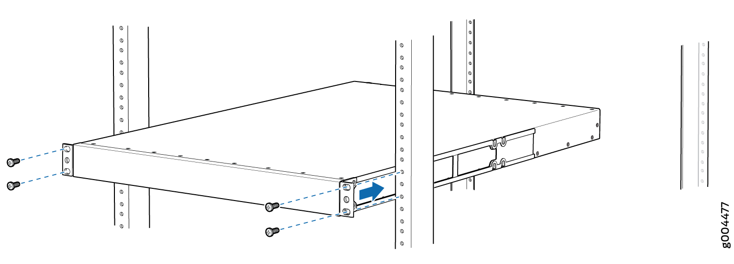
  7. Have a second person secure the front of the switch to the rack using four mounting screws (and cage nuts and washers if your rack requires them.) Tighten the screws. See Figure 2 for examples of connecting the mounting rails and blades.
    Figure 2: Attach EX4600 Switch to RackAttach EX4600 Switch to Rack
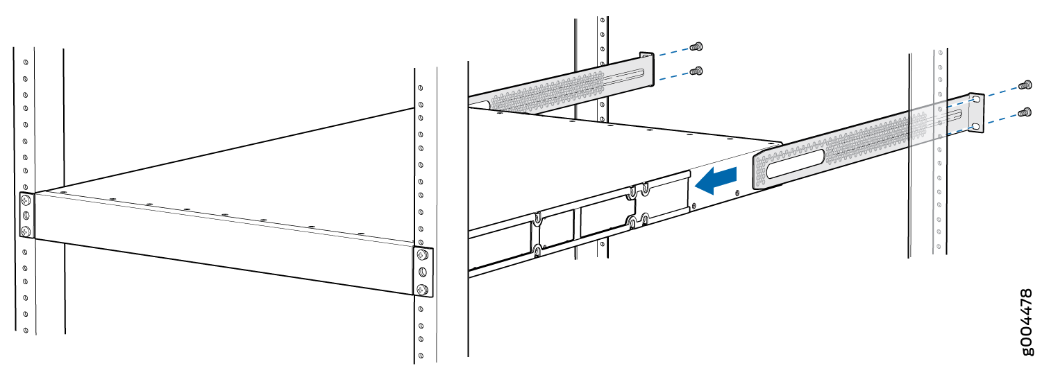
  8. Continue to support the switch while sliding the rear mounting-blades into the channel of the side mounting-rails and securing the blades to the rack. Use the four mounting screws (and cage nuts and washers if your rack requires them) to attach each blade to the rack. Tighten the screws. See Figure 3.
    Figure 3: Slide Mounting Blade into EX4600 Mounting RailSlide Mounting Blade into EX4600 Mounting Rail
  9. Ensure that the switch chassis is level by verifying that all the screws on the front of the rack are aligned with the screws at the back of the rack.