EX4600 Chassis
Chassis Physical Specifications for an EX4600 Switch
The EX4600 switch chassis is a rigid sheet-metal structure that houses the hardware components. Table 1 summarizes the physical specifications of the EX4600 chassis.
Product Number |
Height |
Width |
Depth |
Weight |
|---|---|---|---|---|
EX4600 |
1.72 in. (4.3 cm) |
17.36 in. (44.1 cm) |
20.48 in. (4.37 cm) |
With power supplies and fan modules installed: 21.7lbs ( 9.84 kg) |
Field-Replaceable Units in an EX4600 Switch
Field-replaceable units (FRUs) are components that you can replace at your site. The EX4600 switch FRUs are hot-insertable and hot-removable: you can remove and replace one of them without powering off the switch or disrupting the switching function. FRU types are:
Power supplies
Fan modules
Optical transceivers
Expansion modules
Replace a failed power supply with a blank panel or a new power supply within one minute of removal to prevent chassis overheating. The switch continues to operate with only one power supply running. Replace a failed fan module with a new fan module within one minute of removal to prevent chassis overheating. Do not operate the switch for more than one minute after a fan module or power supply fails.
Table 2 lists the FRUs for the EX4600 switch and actions to take before removing them.
FRU |
Required Action |
|---|---|
Power supplies |
None, if two power supplies are installed as recommended. If only one power is installed, you must power down the switch. See Removing a Power Supply from an EX4600 Switch. |
Fan modules |
None. See Removing a Fan Module from an EX4600 Switch for details. |
Optical transceivers |
None. We recommend that you disable the interface using the set interfaces interface-name disable command before you remove the transceiver. See Disconnect a Fiber-Optic Cable. |
Expansion modules |
None. See Removing an Expansion Module from an EX4600 Switch. |
If you have a Juniper Care service contract, register any addition, change, or upgrade of hardware components at https://www.juniper.net/customers/support/tools/updateinstallbase/ . Failure to do so can result in significant delays if you need replacement parts. This note does not apply if you replace existing components with the same type of component.
See Also
Port Panel of an EX4600 Switch
The fixed portion of the port panel of the EX4600-40F switch supports up to a maximum of 40 logical 10 GbE ports. Twenty-four physical ports (0 through 23) support 10 Gbps small form-factor pluggable plus (SFP+) transceivers. These ports can be configured as access ports. See The Hardware Compatibility Tool for a list of supported transceivers. All 24 of these ports can be used for SFP+ transceivers or SFP+ direct attach copper (DAC) cables. You can use 1-Gigabit Ethernet SFP+ transceivers, 10-Gigabit Ethernet SFP+ transceivers, and SFP+ direct attach copper cables in any access port.
The remaining 16 logical ports are available for four 40 GbE ports (24 through 27) that support up to four quad small-form factor pluggable plus (QSFP+) transceivers. Each QSFP+ port can operate either as a single 40 Gbps port or as a set of 4 independent 10 Gbps ports using QSFP+ breakout cables. The 40 GbE ports can be configured as either access ports or as uplinks. .
When you use the latest OEM part number FCLF8521P2BTL (printed on the transceiver label), you can install 1GbE transceivers (such as QFX-SFP-1GE-T) in any port with no restrictions. The same applies for devices that support 10GbE copper transceivers. However, if you are using the older OEM part number SP7041-M1-JN (not shipped in last 3+ years) instead, do not install 1GbE copper transceivers (such as QFX-SFP-1GE-T) directly above or below another 1GbE copper transceiver. Use only the top row or bottom row to avoid damage to the device caused when the transceivers are installed above or below each other.
Figure 1 shows the port panel of an EX4600 switch.
1 — Electrostatic Discharge (ESD) terminal | 3 — 40 GbE ports (4) |
2 — 10 G ports (24) | 4 — Expansion module bays with cover panels (2) |
Access Port and Uplink Port LEDs on an EX4600 Switch
The Link/Activity and Status LED configuration for an EX4600 switch uses bi-colored LEDs. The two figures in this topic show the location of those LEDs:
-
Figure 2 shows the location of the LEDs on the SFP+ access ports on the EX4600 and Figure 3 shows the location of the LEDs on the QSFP+ uplink ports on the EX4600.
The LED in Figure 2 labeled Link/Activity indicate link activity or a fault. The LED labeled Status in indicates transceiver presence.
Table 3 describes how to interpret the SFP+ port LEDs.
|
LED |
Color |
State |
Description |
|---|---|---|---|
|
Link/Activity |
Unlit |
Off |
The port is administratively disabled, there is no power, the link is down, or there is a fault. |
|
Green |
On steadily |
A link is established, but there is no link activity. |
|
|
Blinking |
A link is established, and there is link activity. |
||
|
Amber |
Blinking |
The beacon is enabled on the port. |
|
|
Status |
Unlit |
Off |
The link is down. |
|
Amber |
Blinking |
The beacon function is enabled on the port. |
|
|
Green |
Blinking |
A 1-Gigabit Ethernet transceiver is installed in the port and the link is established. |
|
|
Green |
On steadily |
A 10-Gigabit Ethernet transceiver is installed in the port and link is established. |
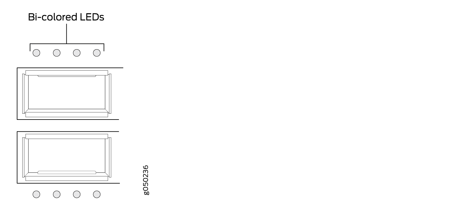
As shown in Figure 3, there are four bi-color LEDs for each QSFP+ port. The first LED is used and the remaining LEDs are not used when the interface is configured for 40-Gigabit Ethernet and connected to a QSFP+ transceiver. All four LEDs are used when the interface is configured for 10-Gigabit Ethernet and the port is connected using an optical split cable or a copper DACBO cable. Table 4 describes how to interpret the QSFP+ LEDs.
|
Color |
State |
Description |
|---|---|---|
|
Unlit |
Off |
The port is administratively disabled, there is no power, the link is down, or there is a fault. Note:
When configured for 10-Gigabit Ethernet, the LED remains unlit only if all four of the 10-Gigabit Ethernet SFP+ breakout links are down. |
|
Green |
On steadily |
A link is established, but there is no link activity. Note:
When configured for 10-Gigabit Ethernet, the LED is lit green when at least one of the four 10-Gigabit Ethernet SFP+ breakout links is established. |
|
Blinking |
A link is established, and there is link activity. Note:
When configured for 10-Gigabit Ethernet, the LED is lit green when at least one of the four 10-Gigabit Ethernet SFP+ breakout links is established. |
|
|
Amber |
Blinking |
All four LEDs blink to indicate the beacon function was enabled on the port. |
Management Panel of an EX4600 Switch
The management panel of the EX4600 switch is located on the Field Replaceable Unit (FRU) side of the switch, as shown in Figure 4. See Figure 5 for management panel details.
1 — Management panel | 3 — Power supply units |
2 — Fan modules |
1 — Status LEDs | 4 — RJ-45 console port (CON) and em0–RJ-45 (1000 Base-T) management Ethernet port (C0) |
2 — em1–SFP management Ethernet port (C1) Cage (socket for either 1 GbE copper SFP or fiber SFP) | 5 — USB port |
3 — Reset button, see caution statement below |
Do not use the Reset button to restart the power sequence unless under the direction of Juniper Networks Technical Assistance Center (JTAC).
The management panel consists of the following components:
-
Status LEDs
-
ALM (Alarm or beacon)
-
Unlit indicates the switch is halted or that there is no alarm.
-
Red indicates a major alarm.
-
Amber indicates a minor alarm.
-
-
SYS (System)
-
Unlit indicates the switch is powered off or halted.
-
Solid green indicates that Junos OS for EX Series is loaded on the switch.
-
Blinking green indicates that the switch is a participating member in a Virtual Chassis.
-
-
MST (Primary) in a Virtual Chassis
-
Unlit indicates the switch is standalone or is a line card member in a Virtual Chassis.
-
Solid green indicates the switch is the primary in a Virtual Chassis.
-
Blinking green indicates the switch is the backup primary in a Virtual Chassis.
-
-
ID (Identification)
-
Unlit indicates the beacon feature is not enabled.
-
Blinking blue indicates the beacon feature is enabled. This feature is enabled using the
request chassis beaconcommand.
-
-
-
Switch model number
-
Management Ports C0 and C1
-
C0–Use the RJ-45 connectors for 10/100/1000 BaseT.
-
C1–Use the SFP connector for 1000 BaseX.
-
-
USB port for image updates.
-
Console port (RJ-45) to support RS-232 serial ports. The LEDs above the port indicate status and link.
Chassis Status LEDs on an EX4600 Switch
The EX4600 switch has four status LEDs on the field-replaceable unit (FRU) end of the chassis, next to the management ports (see Figure 6).
1 — Status LEDs | 3 — RJ-45 console port (CON) and em0–RJ-45 (1000 Base-T) management Ethernet port (C0) |
2 — em1–SFP management Ethernet port (C1) Cage (socket for either 1 GbE copper SFP or fiber SFP) | 4 — USB port |
Do not use the Reset button to restart the power sequence unless under the direction of Juniper Networks Technical Assistance Center (JTAC).
Table 5 describes
the chassis status LEDs on an EX4600 switch, their colors and states,
and the status they indicate. You can view the colors of the three
LEDs remotely through the CLI by issuing the operational mode command show chassis lcd.
|
Name |
Color |
State |
Description |
|---|---|---|---|
|
ALM (Alarm or beacon) |
Unlit |
Off |
The switch is halted or there is no alarm. |
|
Red |
On steadily |
A major hardware fault has occurred, such as a temperature alarm or power failure, and the switch has halted. Power off the EX4600 switch by setting the AC power source outlet to the OFF (O) position, or unplugging the AC power cords. Correct any voltage or site temperature issues, and allow the switch to cool down. Power on the EX4600 switch and monitor the power supply and fan LEDs to help determine where the error is occurring. |
|
|
Amber |
On steadily |
A minor alarm has occurred, such as a software error. Power off the EX4600 switch by setting the AC power source outlet to the OFF (O) position, or unplugging the AC power cords. Power on the EX4600 switch and monitor the status LEDs to ensure that Junos OS boots properly. |
|
|
SYS (System) |
Unlit |
Off |
The switch is powered off or halted. |
|
Green |
On steadily |
Junos OS for EX Series is loaded on the switch. |
|
|
MST (Primary) |
Unlit |
Off |
The switch is standalone. |
|
ID (Identification) |
Unlit |
Off |
The beacon feature is not enabled on the switch. This
feature is enabled using the |
|
Blue |
Blinking |
The beacon feature is enabled on the switch. This feature
is enabled using the |
See Also
Expansion Modules for the EX4600
The EX4600 switch has two bays on the port panel in which you can optionally install one or two expansion modules. The EX4600 supports the same two expansion modules as the QFX5100, which increase port density:
-
EX4600-EM-8F, which provides 8 additional 10-Gigabit Ethernet Enhanced Small Form-Factor Pluggable (SFP+) ports.
-
QFX-EM-4Q, which provides 4 additional 40-Gigabit Quad SFP+ (QSFP+) ports.
The EX4600 is configured for the QFX-EM-4Q by default, but any combination of the two modules is supported. Expansion modules can be hot-inserted or hot-removed. However, when an EX4600-EM-8F is inserted instead of the default QFX-EM-4Q, the new configuration causes the interfaces to temporarily go down. Likewise when an EX4600-EM-8F is running on the EX4600 and it is swapped with a QFX-EM-4Q, the interfaces temporarily go down, which can cause a short disruption in traffic.
Expansion modules and transceivers are not shipped with the switch and must be ordered separately.
EX4600-EM-8F
The EX4600-EM-8F, provides 8 additional 10-Gigabit Ethernet SFP+ ports or 8 additional 1-Gigabit SFP ports to one of the bays in the EX4600 switch. Figure 7 shows the ports and LEDs on the expansion module.
Copper SFP transceivers (1000BASE-T) are restricted to the top four ports or the bottom four ports; fiber SFP transceivers (1000BASE-X) can be used in any of the eight ports. Attempting to stack copper SFP transceivers causes internal damage to the module.
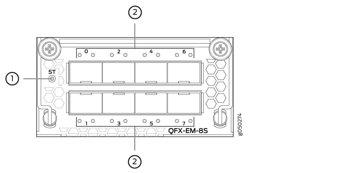
1 — Expansion module status LED | 2 — SFP+ port LEDs |
When the expansion module is inserted into the expansion bay, the chassis detects the additional ports, recognizes them as 10GbE ports, and lights the Status LED.
Table 6 describes the Status LED on the EX4600-EM-8F.
|
LED |
State |
Description |
|---|---|---|
|
ST |
Unlit |
|
|
Green |
|
QFX-EM-4Q
The QFX-EM-4Q, provides 4 additional 40-Gigabit Ethernet QSFP+ ports to one of the bays in the EX4600 switch. Port 0 and port 2 can be used for port channelization by configuring the system mode for 104 port mode.
Figure 8 shows the QFX-EM-4Q ports and LEDs.
1 — Expansion module status LED | 2 — QSFP+ port LEDs |
When the expansion module is inserted into the expansion bay, the chassis detects the additional ports, recognizes them as 40 GbE ports, and lights the Status LED.
Table 7 describes the Status LED on the QFX-EM-4Q expansion module.
|
LED |
State |
Description |
|---|---|---|
|
ST |
Unlit |
|
|
Green |
|