ON THIS PAGE
Fast Track to Rack Installation and Power
This procedure guides you through the simplest steps for the most common installation to get your EX4400 switch in a rack and connect it to power. Have more complex installation needs? See Install the EX4400 Switch.
Install the EX4400 in a Rack
You can install the EX4400 switch on a desktop or other level surface, in a two-post or four-post rack, or on a wall. We’ll walk you through the steps to install an AC-powered switch in a two-post rack.
Before you install, review the following:
- Place the switch on a flat, stable surface.
- Wrap and fasten one end of the ESD grounding strap around your bare wrist, and connect the other end to a site ESD point.
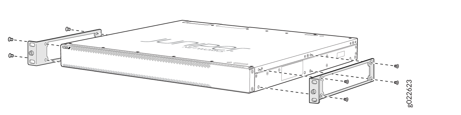
- Attach the mounting brackets to the sides of the EX4400 switch
using the eight screws in the rack mount kit and a screwdriver.
-
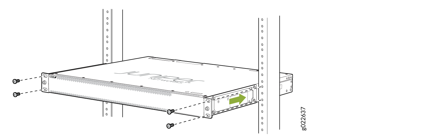
Lift the switch and position it in the rack. Position the switch so that the AIR IN labels on the fan modules are facing the cold aisle, or the AIR OUT labels on the fan modules are facing the hot aisle. Line up the bottom hole in each mounting bracket with a hole in each rack post, making sure the switch is level.
-
While you’re holding the switch in place, have a second person insert and tighten the rack mount screws to secure the mounting brackets to the rack posts. Tighten the screws in the two bottom holes first, and then tighten the screws in the two top holes.
-
Check that the mounting brackets on each side of the rack are lined up with each other.
-
Cover the empty extension module and the power supply slots by using the covers that came with the switch.
Connect to Power
To connect the EX4400 switch to AC power, you must do the following:
Ground the EX4400 Switch
To ground the EX4400 switch, do the following:
- Connect one end of the grounding cable to a proper earth ground, such as the rack.
- Place the grounding lug attached to the grounding cable over
the protective earthing terminal on the rear panel.
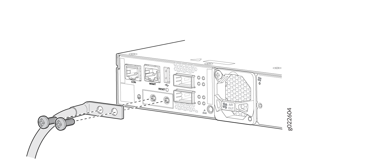
-
Secure the grounding lug to the protective earthing terminal using the 10-32 x .25-in. screws with #10 split-lock washers.
-
Dress the grounding cable. Be sure that the cable doesn’t block access to or touch other device components, and that it doesn’t drape where people could trip over it.
Connect the Power Cord and Power On the Switch
For information about the supported AC power cord specifications, see Table 1.
To connect the power cord, do the following:
-
Ensure that the power supply is fully inserted in the rear panel of the switch.
-
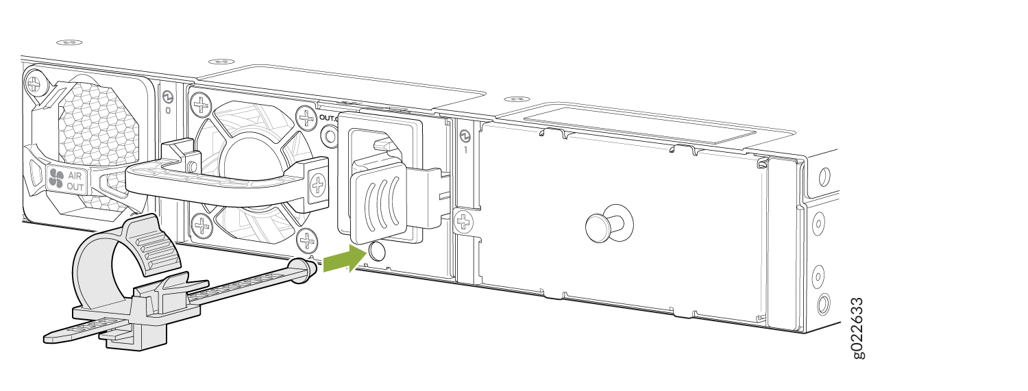
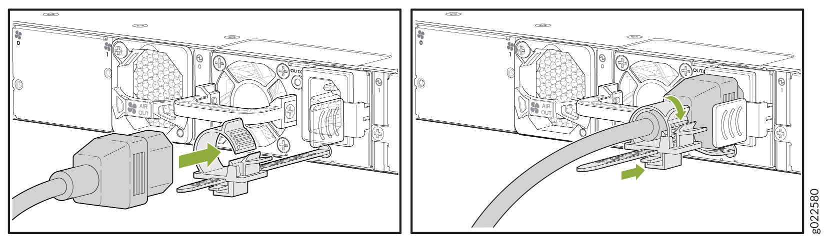
On the rear panel, connect the retainer strip and power cord to the AC power socket:
-
Push the end of the retainer strip into the hole next to the AC power socket until it snaps into place. Ensure that the loop in the retainer strip points upward.
-
Press the small tab on the retainer strip to loosen the loop.
-
Slide the loop until you have enough space to insert the power cord into the AC power socket.
-
Firmly plug in the power cord to the AC power socket on the switch.
-
Slide the loop toward the power supply until it is snug against the base of the power cord coupler.
-
Press the tab on the loop, and draw out the loop into a tight circle.
-
-
If the AC power source outlet has a power switch, turn it off.
-
Plug in the power cord to the AC power source outlet.
-
If the AC power source outlet has a power switch, turn it on. The switch powers on as soon as you plug it in. The EX4400 doesn't have a power switch.
-
Check to see that the
OUT.OKLED on the power supply is lit steadily green. If not, disconnect the power supply from the power source. You’ll need to replace the power supply (see Maintain the EX4400 Power System in the EX4400 Switch Hardware Guide).