ON THIS PAGE
Install the EX4100 Switch
This topic guides you through the steps to install EX4100 switches.
Unpack the EX4100 Switch
Juniper Networks ships EX4100 switches in a cardboard carton, secured with foam packing material. The carton has an accessory compartment.
The shipping carton completely protects EX4100 switches. Leave the switches safely in the carton until you are ready to begin installation.
To unpack the switch:
- Move the shipping carton to a staging area as close to the installation site as possible, but where you have enough room to remove the system components.
- Position the carton so that the arrows are pointing up.
- Open the top flaps on the shipping carton.
- Pull out the packing material holding the switch in place.
- Verify the parts received against the inventory on the label attached to the carton (see Packing List for an EX4100 Switch).
- Save the shipping carton and packing materials in case you need to move or ship the switch later.
Packing List for an EX4100 Switch
The switch shipment includes a packing list. Check the parts you receive with the switch against the items on the packing list. The packing list specifies the part number and provides a description of each part in your order. The parts shipped match the switch model you ordered (see EX4100 Models and Specifications).
If any part on the packing list is missing, contact your customer service representative or contact Juniper customer care from within the U.S. or Canada by telephone at 1-888-314-5822. For international-dial or direct-dial options in countries without toll-free numbers, see https://www.juniper.net/support/requesting-support.html.
See:
-
Table 1 for inventory of components provided with EX4100-48P, EX4100-48T, EX4100-24P, and EX4100-24T models.
-
Table 2 for inventory of components provided with EX4100-48MP and EX4100-24MP models.
|
Component |
Quantity |
|
|---|---|---|
|
Switch |
1 |
|
|
Fan modules |
2 preinstalled |
|
|
Power supplies |
1 (AC or DC) preinstalled |
|
|
AC power cord appropriate for your geographical location |
1 |
|
|
AC power cord retainer |
1 |
|
|
DC PSU terminal connector |
1 (shipped along with DC switch models only) |
|
|
Dust covers for SFP ports |
8 preinstalled |
|
|
Mounting brackets (2-post) |
2 |
|
|
Rubber feet |
4 |
|
|
Documentation Roadmap/Warranty Card |
1 |
|
|
Juniper Networks Product Warranty |
1 |
|
|
End User License Agreement |
1 |
|
|
Component |
Quantity |
|
|---|---|---|
|
Switch |
1 |
|
|
Fan modules |
2 preinstalled |
|
|
Power supplies |
1 (AC) preinstalled |
|
|
AC power cord appropriate for your geographical location |
1 |
|
|
AC power cord retainer |
1 |
|
|
Dust covers for SFP ports |
8 preinstalled |
|
|
Mounting brackets (2-post) |
2 |
|
|
Rubber feet |
4 |
|
|
Documentation Roadmap/Warranty Card |
1 |
|
|
Juniper Networks Product Warranty |
1 |
|
|
End User License Agreement |
1 |
|
Update Base Installation Data
Update the installation base data if any addition or change to the installation base occurs or if the installation base is moved. Juniper Networks is not responsible for not meeting the hardware replacement SLA for products that do not have accurate installation base data.
Update your installation base at https://supportportal.juniper.net/s/CreateCase .
Mount an EX4100 Switch on Two Posts in a Rack or Cabinet
Before mounting the switch on two posts in a rack:
-
Verify that the site meets the requirements described in Environmental Requirements and Specifications for EX4100 Switches.
-
Place the rack in its permanent location, allowing adequate clearance for airflow and maintenance, and secure it to the building structure.
-
Read General Safety Guidelines and Warnings, with particular attention to Chassis and Component Lifting Guidelines.
Ensure that you have the following parts and tools available:
-
Phillips (+) screwdriver, number 2 (not provided).
-
Screws to secure the chassis to the rack (not provided).
You can mount an EX4100 switch on two posts of a 19-in. rack or cabinet by using the front mounting brackets provided with the switch. (The remainder of this topic uses rack to mean rack or cabinet.)
You can also mount the switch on four posts of a four-post rack by using the mounting brackets provided with the separately orderable four-post rack-mounting kit. See Mount an EX4100 Switch on Four Posts in a Rack or Cabinet.
One person must be available to lift the switch while another secures the switch to the rack.
If you are mounting multiple units on a rack, mount the heaviest unit at the bottom of the rack and mount the other units from the bottom of the rack to the top in decreasing order of the weight of the units.
To mount the switch on two posts in a rack:
-
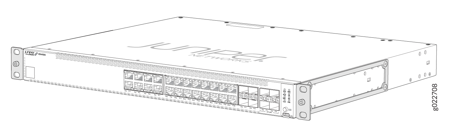
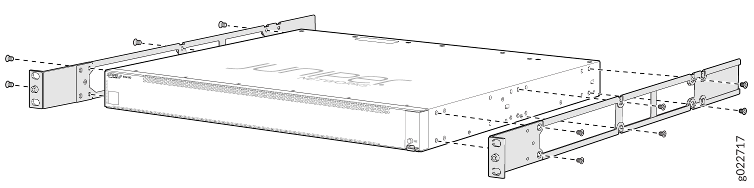
Remove the switch from the shipping carton (see Unpack the EX4100 Switch).
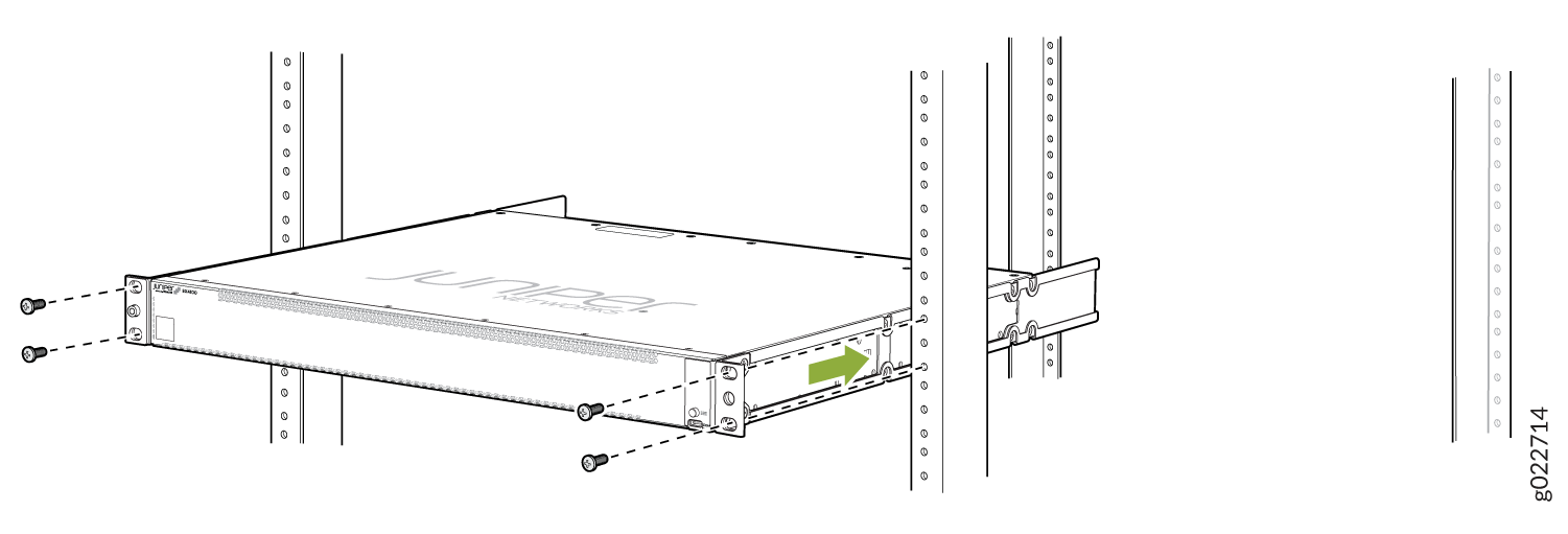
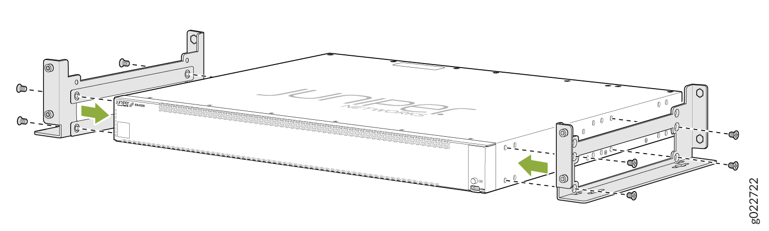
Figure 1: EX4100 Chassis with Front-Mounting Brackets
-
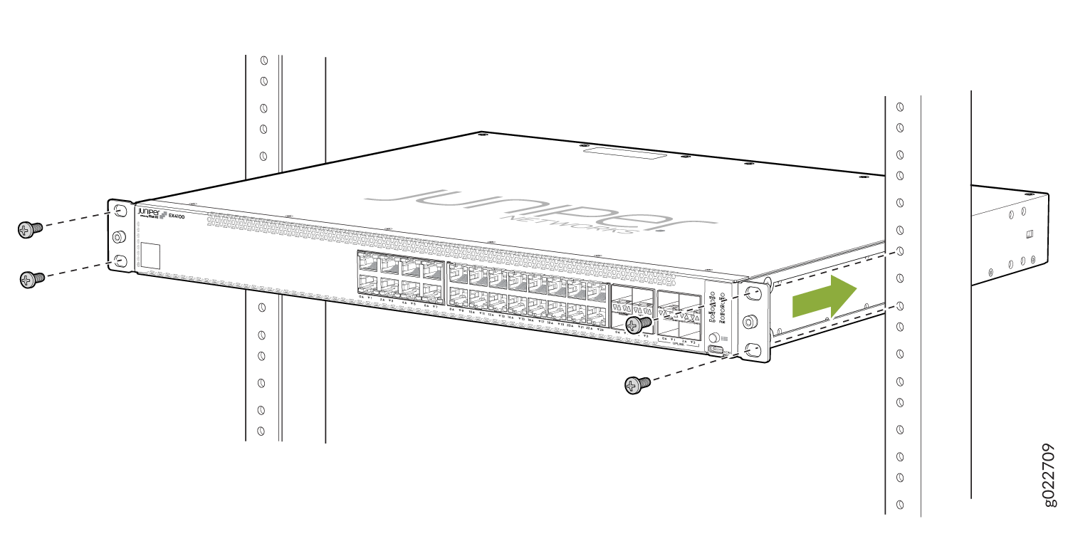
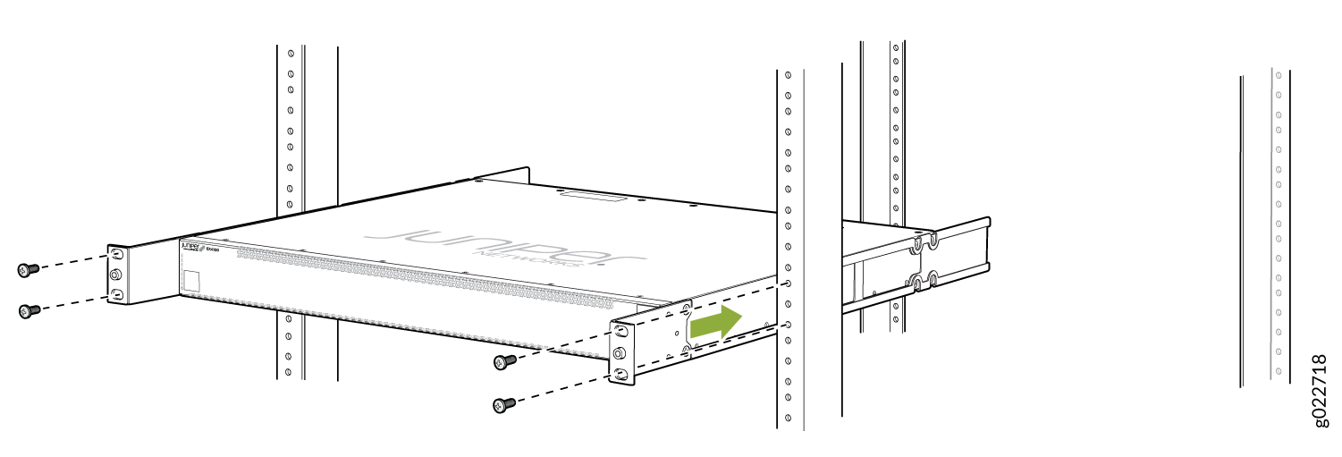
Have one person grasp both sides of the switch, lift the switch, and
position it in the rack, aligning the mounting bracket holes with the
threaded holes in the rack or cabinet rail. Have the person align the bottom
hole in each mounting bracket with a hole in each rack rail, making sure
that the chassis is level. See Figure 2.
Figure 2: Mounting the Switch on Two Posts in a Rack
-
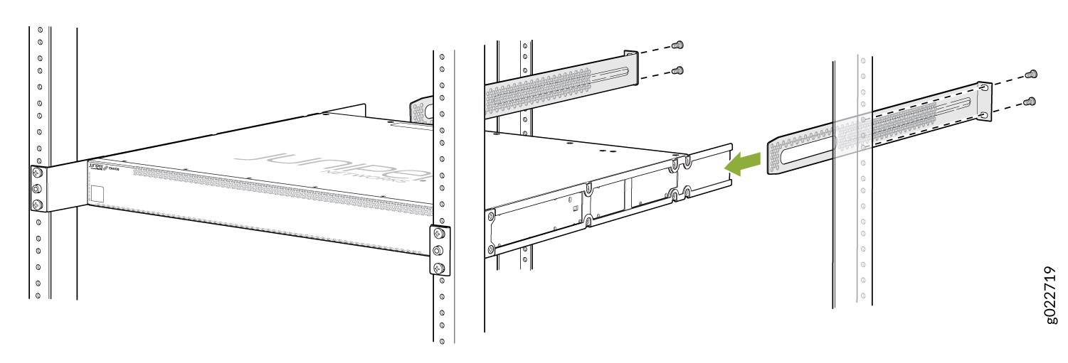
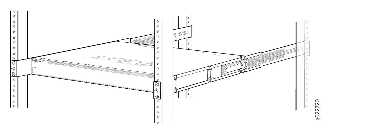
Ensure that the switch chassis is level by verifying that all screws on one
side of the rack are aligned with the screws on the other side.
Figure 3: EX4100 Chassis Installed in Rack

Mount an EX4100 Switch on Four Posts in a Rack or Cabinet
Before mounting the switch on four posts in a rack:
-
Verify that the site meets the requirements described in EX4100 and EX4100-F Site Guidelines and Requirements.
-
Place the rack in its permanent location, allowing adequate clearance for airflow and maintenance, and secure it to the building structure.
-
Read General Safety Guidelines and Warnings, with particular attention to Chassis and Component Lifting Guidelines.
If you want to mount the switch in a recessed position, attach the 2-in.-recessed front-mounting brackets provided in the separately orderable four-post rack-mounting kit. See Mount an EX4100 Switch in a Recessed Position in a Rack or Cabinet.
Ensure that you have the following parts and tools available:
-
Phillips (+) screwdriver, number 2
-
12 flat-head 4x6-mm Phillips mounting screws (provided with the four-post rack-mounting kit)
-
One pair of side-mounting rails (provided with the four-post rack-mounting kit)
-
One pair of rear-mounting blades (provided with the four-post rack-mounting kit)
-
Screws to secure the chassis and the rear-mounting blades to the rack (not provided)
You can mount an EX4100 switch on four posts of a 19-in. rack or cabinet by using the separately orderable four-post rack-mounting kit. (The remainder of this topic uses rack to mean rack or cabinet.)
If you need to mount the switch in a recessed position on a four-post rack, you can use the 2-in.-recessed front-mounting brackets provided in the separately orderable four-post rack-mounting kit.
One person must be available to lift the switch while another secures the switch to the rack.
If you are mounting multiple units on a rack, mount the heaviest unit at the bottom of the rack and mount the other units from the bottom of the rack to the top in decreasing order of the weight of the units.
To mount the switch on four posts in a rack:
-
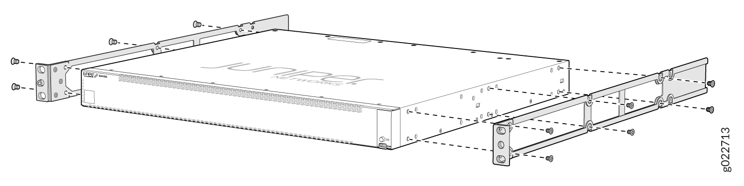
As shown in Figure 4, align the side mounting rails along the side panels of the switch
chassis and insert and tighten the twelve 4x6 mm Phillips flat-head mounting
screws to secure the side panels to the two sides of the switch
chassis.
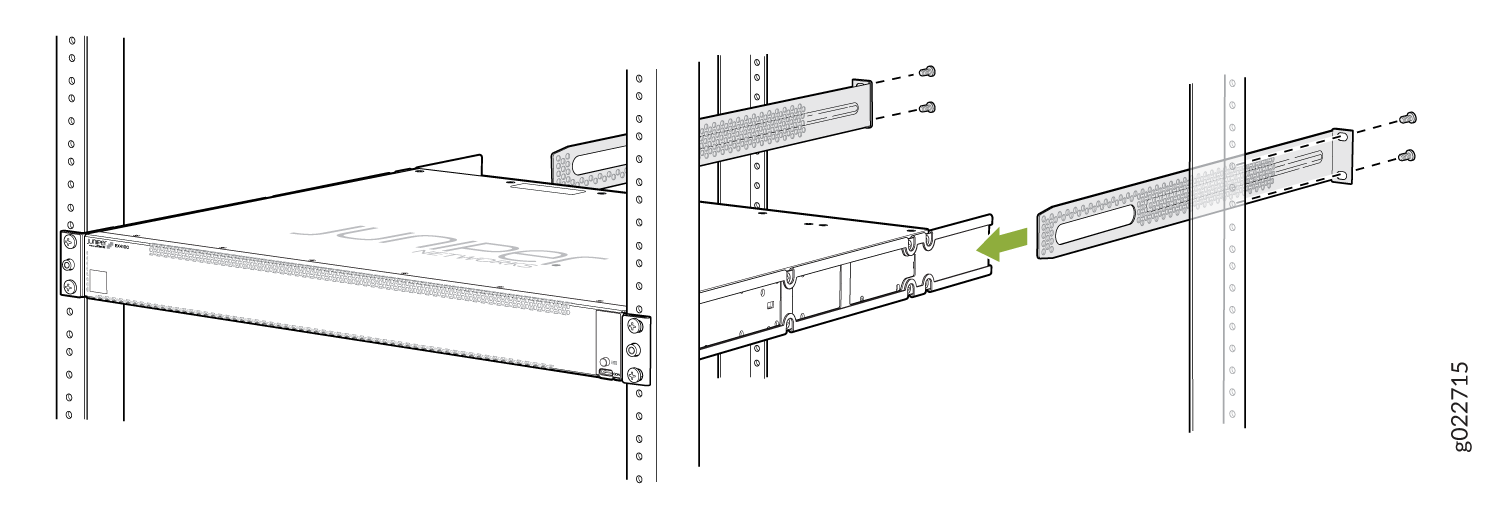
Figure 4: Attaching the Side Mounting Rail to the Switch Chassis
-
Have one person grasp both sides of the switch, lift the switch, and
position it in the rack, aligning the holes on the side mounting rail with
the threaded holes in the front post of the rack. Have the person align the
bottom hole in both the front-mounting brackets with a hole in each rack
rail, making sure that the chassis is level. See Figure 5.
Figure 5: Mounting the Switch to the Front Posts in a Rack
-
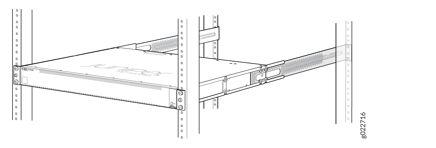
Slide the rear-mounting blades into the side mounting-rails. See Figure 6.
Figure 6: Sliding the Rear-Mounting Blades into the Side Mounting Rails
-
Attach the rear-mounting blades to the rear post by using the appropriate
screws for your rack. Tighten the screws.
Figure 7: Chassis Fully Installed in the Rack
Mount an EX4100 Switch in a Recessed Position in a Rack or Cabinet
You can mount an EX4100 switch in a rack or cabinet such that the switch is recessed inside the rack from the front of the rack by 2 inches. You can use the 2-in.-recessed front-mounting brackets provided in the separately orderable four-post rack-mounting kit to mount the switch in a recessed position.
Reasons that you might want to mount the switch in a recessed position include:
-
You are mounting the switch in a cabinet, and the cabinet doors do not close completely unless the switch is recessed.
-
The switch you are mounting has transceivers installed in the uplink ports, and the transceivers in the uplink ports protrude from the front of the switch.
Before you mount an EX4100 switch in a recessed position inside a 19-in. four-post rack:
-
Verify that the site meets the requirements described in EX4100 Site Guidelines and Requirements.
-
Place the rack in its permanent location, allowing adequate clearance for airflow and maintenance, and secure it to the building structure.
-
Read General Safety Guidelines and Warnings, with particular attention to Chassis and Component Lifting Guidelines.
Ensure that you have the following parts and tools available:
-
Number 2 Phillips (+) screwdriver (not provided)
-
Eight screws to secure the mounting brackets to the rack (not provided)
-
An ESD grounding strap (not provided)
-
Recessed-mounting brackets to mount the switch in a recessed position from the front posts of a rack—2 (provided with the four-post rack-mounting kit)
-
Flat head 4-40 Phillips screws to attach the recessed-mounting brackets to the side rails of the bracket assembly—6 (provided with the four-post rack-mounting kit)
-
Flat head 4x6-mm Phillips screws to attach the front-mounting bracket assembly to the chassis—12 (provided with the four-post rack-mounting kit)
To mount an EX4100 switch in a recessed position from the front posts of a 19-in. four-post rack:
-
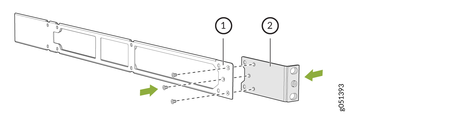
Remove the flush mounting bracket and then attach the recessed-mounting
brackets provided with the four-post rack-mounting kit to the side rails by
using the flat head 4-40 Phillips screws provided with the four-post
rack-mounting kit .
Figure 8: Attach the Recessed-Mounting Bracket to the Side Rail
-
Insert the flat head 4x6-mm Phillips screws to attach the recessed-mounting
bracket assembly into the aligned holes on the chassis provided with the
four-post rack-mounting kit and tighten the screws.
Figure 9: Attach the Recessed-Mounting Bracket Assembly to the Switch
-
Have a second person secure the mounting brackets to the rack by using four
screws appropriate for your rack. Tighten the screws.
Figure 10: Secure the Switch to the Front Posts of a Rack
-
Secure the rear-mounting brackets to the rear post of the rack by using
four screws appropriate for your rack.
Figure 11: Secure the Switch to the Rear Post of the Rack by Using the Rear-Mounting Brackets
-
Look around the installed switch to ensure that the switch is installed
correctly.
Figure 12: Chassis Fully Installed in Rack
Mount an EX4100 Switch on a Wall
Before mounting a switch on a wall:
-
Verify that the site meets the requirements described in Site Preparation Checklist for EX4100 Switches .
-
Read General Safety Guidelines and Warnings, with particular attention to Chassis and Component Lifting Guidelines.
Ensure that you have the following parts and tools available:
-
2 wall-mounting brackets (provided in the wall-mounting kit)
-
12 wall-mounting bracket screws (provided in the wall-mounting kit)
-
6 mounting screws (8-32 x 1.25 in. or M4 x 30 mm) (not provided)
-
Hollow wall anchors rated to support up to 75 lb (34 kg) if you are not screwing the screws directly into wall studs (not provided)
-
Phillips (+) screwdriver, number 2
You can mount an EX4100 switch on a wall by using the separately orderable wall-mounting kit.
To mount one or two switches on a wall:
-
Attach the wall-mounting brackets to the sides of the chassis using four
wall-mounting bracket screws on each side, as shown in Figure 13.
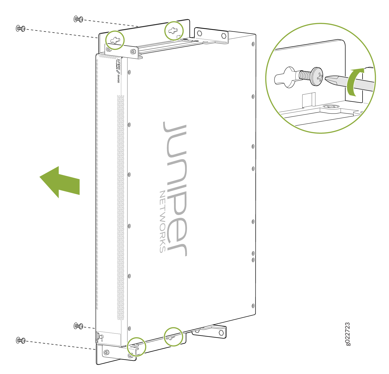
Figure 13: Attaching Wall-Mounting Brackets to a Switch Chassis
-
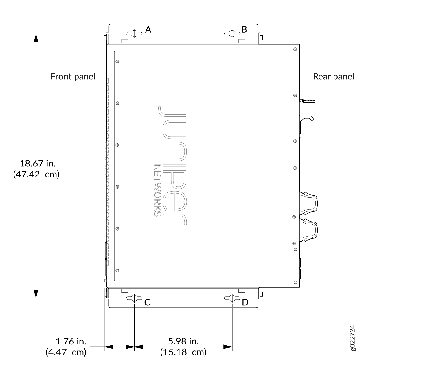
Drill and install mounting screws as per below procedure.
Note:
Tighten the screws only partway in, leaving about 1/4 in. (6 mm) distance between the head of the screw and the wall.
-
Drill a hole (D) at a distance of 18.67 in. (47.43 cm) on a plumb
line down from screw B and install a mounting screw.
Figure 14: Measurements for Installing Mounting Screws
-
Drill a hole (D) at a distance of 18.67 in. (47.43 cm) on a plumb
line down from screw B and install a mounting screw.