EX4100 Models and Specifications
This topic provides details of the EX4100 models and their specifications, information on number of ports and PoE support, throughput, and components in the shipment for each model.
The EX4100 line of switches consist of both PoE and non-PoE models and multigigabit port models. These switches run on either AC or DC power and support either back-to-front or front-to-back airflow.
Let's take a look at the different EX4100 models and their specifications.
|
Gigabit Models |
Multigigabit |
|---|---|
EX4100-24P
Components on the Front and Rear Panels of EX4100-24P Switches
Figure 1 shows the front view of an EX4100-24P switch.
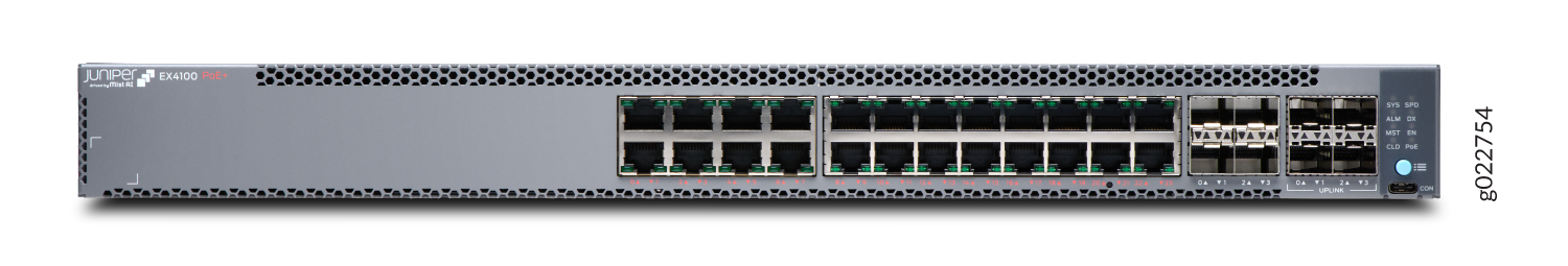
Figure 2 show the rear view of an EX4100-24P switch with AC power supply.
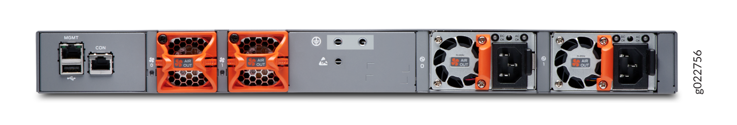
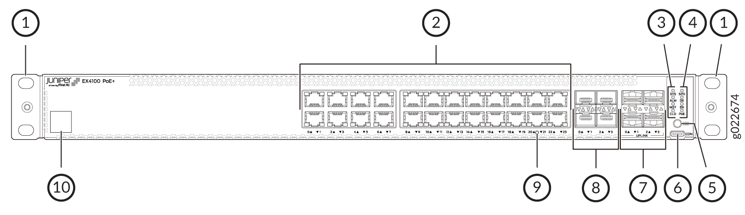
Figure 3 shows the components on the front panel of an EX4100-24P switch.
-
Front mounting brackets
-
10/100/1000BASE-T RJ-45 network ports. These ports in EX4100-24P switches support PoE+ (30 W by default).
-
Chassis status LEDs (labeled SYS, ALM, MST, and CLD)
-
Port mode LEDs (labeled SPD, DX, EN, and PoE)
-
Factory Reset/Mode button
-
RS232 to USB Type-C console port
-
1GE/10GE SFP+ MACsec-enabled uplink ports
-
10GE/25GE SFP28 Virtual Chassis ports
-
Reset button
-
Claim code label
Claim code labels for 24 port EX4100 models are on the front panels; for 48 port EX4100 models, claim code labels are on the rear panels.
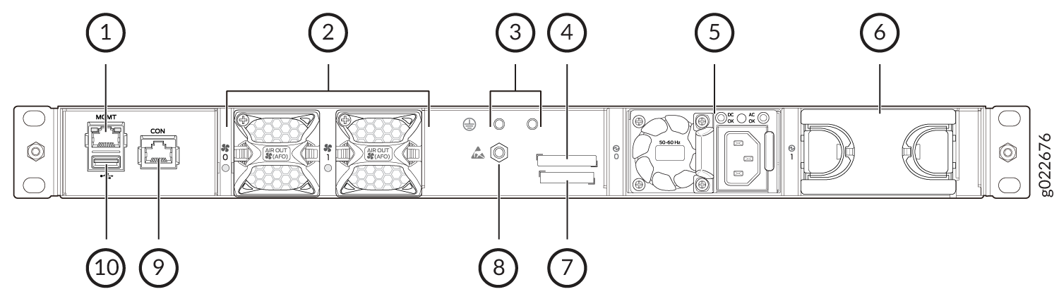
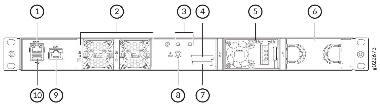
Figure 4 shows the components on the rear panel of an EX4100-24P switch with an AC power supply.
-
RJ-45 management port (labeled MGMT)
-
Fan modules
-
Protective earthing terminal
-
CLEI code label
-
AC power supply
-
Empty slot for power supply
-
Serial number
-
Electrostatic discharge (ESD) point
-
RJ-45 console port (labeled CON)
-
USB 2.0 Type-A port
Table 2 lists the components shipped with EX4100-24P switch models.
Table 3 describes the physical specifications and ports of EX4100-24P switches.
|
Model number |
Fan Modules |
Power Supply |
First Junos OS Release |
|---|---|---|---|
|
EX4100-24P |
Two fan modules with front-to-back airflow, indicated by the label AIR OUT. |
A 920W AC power supply with the AIR OUT label. |
22.2R1 |
|
Item |
Description |
|---|---|
|
Chassis Dimensions |
Height—1.72 in (4.37 cm) |
|
Depth—With no power supply and fan module 13.78 in (35 cm) Depth—With no power supply and fan module 15.05 in (38.24 cm) |
|
|
Width—With power supply and fan module installed 17.36 in in (44.09 cm) |
|
|
Weight |
6315g - with power supply and fan module |
|
Built-in ports |
|
|
PoE Ports |
24 - PoE+ (30 W by default) |
EX4100-24T
Components on the Front and Rear Panels of EX4100-24T Switches
EX4100-24T shows the front view of an EX4100-24T switch.
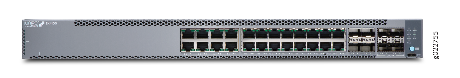
Figure 6 show the rear view of an EX4100-24T switch with AC power supply.
Figure 7 shows the components on the front panel of an EX4100-24T switch.

1 — Front mounting brackets | 6 — RS232 to USB Type-C console port |
2 — 10/100/1000BASE-T RJ-45 non-PoE network ports | 7 — 1GE/10GE SFP+ MACsec-enabled uplink ports |
3 — Chassis status LEDs (labeled SYS, ALM, MST, and CLD) | 8 — 10GE/25GE SFP28 Virtual Chassis ports |
4 — Port mode LEDs (labeled SPD, DX, and EN) | 9 — Reset button |
5 — Factory Reset/Mode button | 10 — Claim Code label |
Figure 8 shows the components on the rear panel of an EX4100-24T switch with an AC power supply.
-
RJ-45 management port (labeled MGMT)
-
Fan modules
-
Protective earthing terminal
-
CLEI code label
-
AC power supply
-
Empty slot for power supply
-
Serial number
-
Electrostatic discharge (ESD) point
-
RJ-45 console port (labeled CON)
-
USB 2.0 Type-A port
Figure 9 shows the components on the rear panel of an EX4100-24T switch with a DC power supply.
-
RJ-45 management port (labeled MGMT)
-
Fan modules
-
Protective earthing terminal
-
CLEI code label
-
DC power supply
-
Empty slot for power supply
-
Serial number
-
Electrostatic discharge (ESD) point
-
RJ-45 console port (labeled CON)
-
USB 2.0 Type-A port
Table 4 lists the components shipped with EX4100-24T switch models.
Table 5 describes the physical specifications, ports, and throughput of EX4100-24T switches.
|
Model number |
Fan Modules |
Power Supply |
First Junos OS Release |
|---|---|---|---|
|
EX4100-24T |
Two fan modules with front-to-back airflow, indicated by the label AIR OUT. |
A 150W AC power supply with the AIR OUT label. |
22.2R1 |
|
EX4100-24T-DC |
Two fan modules with front-to-back airflow, indicated by the label AIR OUT. |
A 150W DC power supply with the AIR OUT label. |
22.2R1 |
|
Item |
Description |
|---|---|
|
Chassis Dimensions |
Height - 1.72 in (4.37 cm) |
|
Depth - With no power supply and fan module 13.78 in (35 cm) |
|
|
Depth - With power supply and fan module installed 15.05 in (38.24 cm) |
|
|
Width—With power supply and fan module installed 17.36 in in (44.09 cm) |
|
|
Weight |
5875g - with power supply and fan module |
|
Built-in ports |
|
|
PoE Ports |
0 |
EX4100-48P
Components on the Front and Rear Panels of EX4100-48P Switches
Figure 10 shows the front view of an EX4100-48P switch.
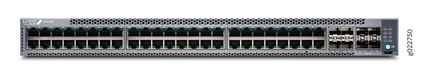
Figure 11 shows the rear view of an EX4100-48P switch with AC power supply.
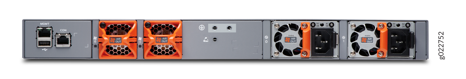
Figure 12 shows the components on the front panel of an EX4100-48P switch.
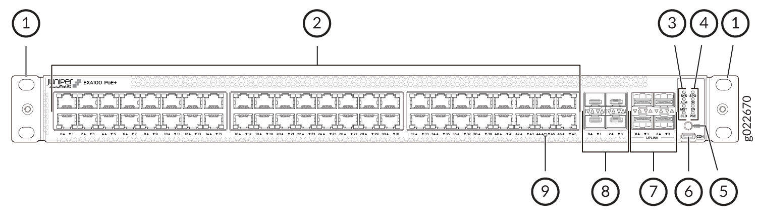
1 — Front mounting brackets | 6 — RS232 to USB Type-C console port |
2 — 10/100/1000BASE-T RJ-45 network ports. These ports in EX4100-48P switches support PoE+ (30 W by default). | 7 — 1GE/10GE SFP+ MACsec-enabled uplink ports |
3 — Chassis status LEDs (labeled SYS, ALM, MST, and CLD) | 8 — 10GE/25GE SFP28 Virtual Chassis ports |
4 — Port mode LEDs (labeled SPD, DX, EN, and PoE) | 9 — Reset button |
5 — Factory Reset/Mode button |
Figure 13 shows the components on the rear panel of an EX4100-48P switch with an AC power supply.
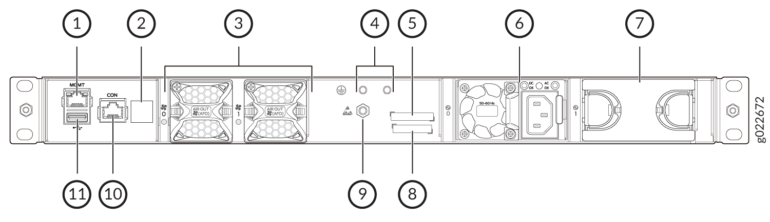
1 — RJ-45 management port (labeled MGMT) | 7 — Empty slot for power supply |
2 — Claim code label | 8 — Serial number |
3 — Fan modules | 9 — Electrostatic discharge (ESD) point |
4 — Protective earthing terminal | 10 — RJ-45 console port (labeled CON) |
5 — CLEI code label | 11 — USB 2.0 Type-A port |
6 — AC power supply |
Table 6 lists the components shipped with EX4100-48P switch models.
Table 7 describes the physical specifications and ports EX4100-48P switches.
|
Model number |
Fan Modules |
Power Supply |
First Junos OS Release |
|---|---|---|---|
|
EX4100-48P |
Two fan modules with front-to-back airflow, indicated by the label AIR OUT. |
A 920W AC power supply with the AIR OUT label. |
22.2R1 |
|
Item |
Description |
|---|---|
|
Chassis Dimensions |
Height - 1.72 in (4.37 cm) |
|
Depth - With no power supply and fan module 13.78 in (35 cm) |
|
|
Depth - With power supply and fan module installed 15.05 in (38.24 cm) |
|
|
Width—With power supply and fan module installed 17.36 in in (44.09 cm) |
|
|
Weight |
6495g - with power supply and fan module |
|
Built-in ports |
|
|
PoE Ports |
48 PoE+ (30 W by default) |
EX4100-48T
Components on the Front and Rear Panels of EX4100-48T Switches
Figure 14 shows the front view of an EX4100-48T switch.
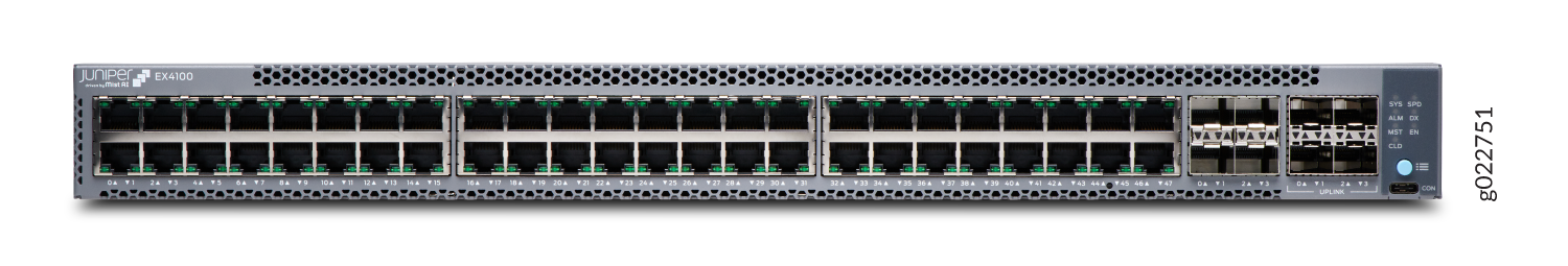
Figure 15 shows the rear view of an EX4100-48T switch with AC power supply.
Figure 16 shows the components on the front panel of an EX4100-48T switch.
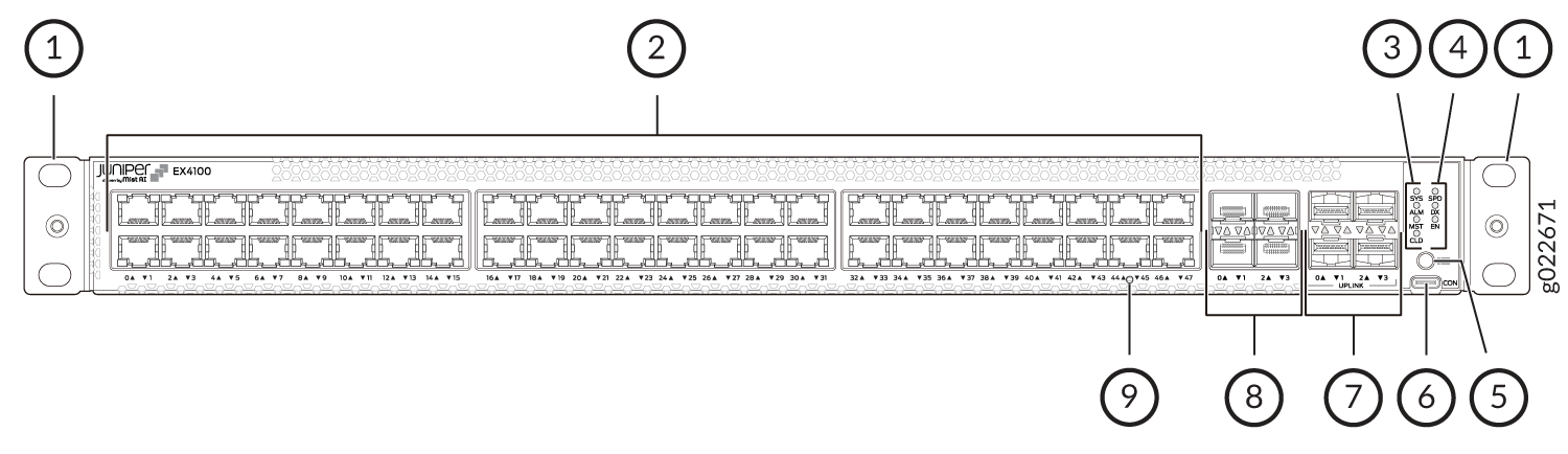
1 — Front mounting brackets | 6 — RS232 to USB Type-C console port |
2 — 10/100/1000BASE-T RJ-45 non-PoE network ports | 7 — 1GE/10GE SFP+ MACsec-enabled uplink ports |
3 — Chassis status LEDs (labeled SYS, ALM, MST, and CLD) | 8 — 10GE/25GE SFP28 Virtual Chassis ports |
4 — Port mode LEDs (labeled SPD, DX, and EN) | 9 — Reset button |
5 — Factory Reset/Mode button |
Figure 17 shows the components on the rear panel of an EX4100-48T switch with an AC power supply.
1 — RJ-45 management port (labeled MGMT) | 7 — Empty slot for power supply |
2 — Claim code label | 8 — Serial number |
3 — Fan modules | 9 — Electrostatic discharge (ESD) point |
4 — Protective earthing terminal | 10 — RJ-45 console port (labeled CON) |
5 — CLEI code label | 11 — USB 2.0 Type-A port |
6 — AC power supply |
Figure 18 shows the components on the rear panel of an EX4100-48T switch with a DC power supply.
1 — RJ-45 management port (labeled MGMT) | 6 — Empty slot for power supply |
2 — Fan modules | 7 — Serial number |
3 — Protective earthing terminal | 8 — Electrostatic discharge (ESD) point |
4 — CLEI code label | 9 — RJ-45 console port (labeled CON) |
5 — DC power supply | 10 — USB 2.0 Type-A port |
Table 8 lists the components shipped with EX4100-48T switch models.
Table 9 describes the physical specifications and ports of EX4100-48T switches.
|
Model number |
Fan Modules |
Power Supply |
First Junos OS Release |
|---|---|---|---|
|
EX4100-48T |
Two fan modules with front-to-back airflow, indicated by the label AIR OUT. |
A 150W AC power supply with the AIR OUT label. |
22.2R1 |
|
EX4100-48T-AFI |
Two fan modules with back-to-front airflow, indicated by the label AIR IN. |
A 150 W AC power supply with the AIR IN label. |
22.2R1 |
|
EX4100-48T-DC |
Two fan modules with front-to-back airflow, indicated by the label AIR OUT. |
A 150 W DC power supply with the AIR OUT label. |
22.2R1 |
|
Item |
Description |
|---|---|
|
Chassis Dimensions |
Height - 1.72 in (4.37 cm) |
|
Depth - With no power supply and fan module 13.78 in (35 cm) |
|
|
Depth - With power supply and fan module installed 15.05 in (38.24 cm) |
|
|
Width—With power supply and fan module installed 17.36 in in (44.09 cm) |
|
|
Weight |
6010g - with power supply and fan module |
|
Built-in ports |
|
|
PoE Ports |
0 |
EX4100-24MP
Components on the Front and Rear Panels of EX4100-24MP Switches
Figure 19 shows the front view of an EX4100-24MP switch.
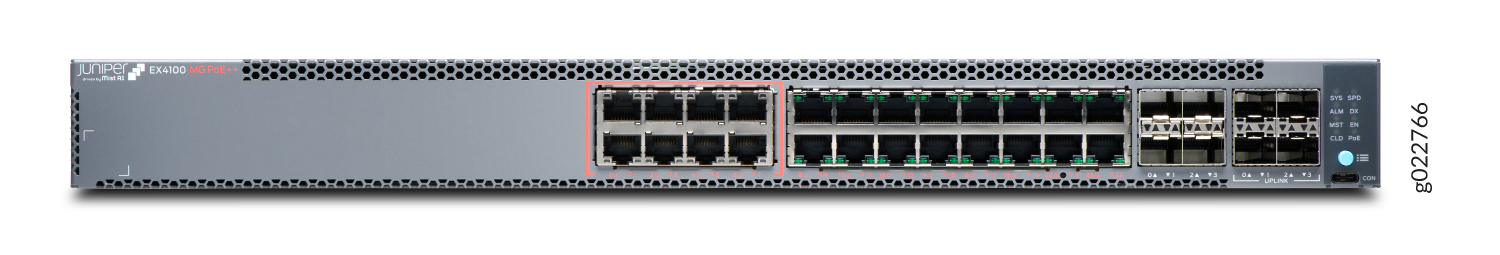
Figure 20 shows the rear view of an EX4100-24MP switch with AC power supply.
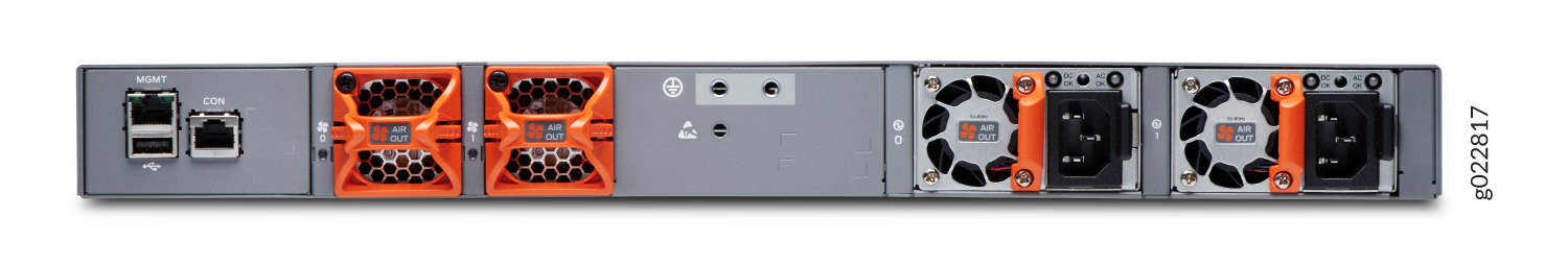
Figure 21 shows the components on the front panel of an EX4100-24MP switch.

1 — Front mounting brackets | 6 — RS232 to USB Type-C console port |
2 — Eight 1/2.5/5/10 GE MACsec-enabled network ports. Sixteen 1 GE BASE-T RJ-45 network ports. These ports in EX4100-24MP support PoE++ (90 W). | 7 — 1/10 GE SFP+ MACsec-enabled uplink ports |
3 — Chassis status LEDs (labeled SYS, ALM, MST, and CLD) | 8 — 10/25 GE SFP28 Virtual Chassis ports |
4 — Port mode LEDs (labeled SPD, DX, EN and PoE) | 9 — Reset button |
5 — Factory Reset/Mode button | 10 — Claim Code label |
Figure 22 shows the components on the rear panel of an EX4100-24MP switch with an AC power supply.

1 — RJ-45 management port (labeled MGMT) | 7 — Empty slot for power supply |
2 — Claim Code label (for EX4100-MP switches) | 8 — Serial number |
3 — Fan modules | 9 — Electrostatic discharge (ESD) point |
4 — Protective earthing terminal | 10 — RJ-45 console port (labeled CON) |
5 — CLEI code label | 11 — USB 2.0 Type-A port |
6 — AC power supply |
Table 10 lists the components shipped with EX4100-24MP switch models.
Table 11 describes the physical specifications and ports of EX4100-24MP switches.
|
Model number |
Fan Modules |
Power Supply |
First Junos OS Release |
|---|---|---|---|
|
EX4100-24MP |
Two fan modules with front-to-back airflow, indicated by the label AIR OUT. |
A 920W AC power supply with the AIR OUT label. |
22.3R1 |
|
Item |
Description |
|---|---|
|
Chassis Dimensions |
Height - 1.72 in (4.37 cm) |
|
Depth - With no power supply and fan module 13.78 in (35 cm) |
|
|
Depth - With power supply and fan module installed 15.05 in (38.24 cm) |
|
|
Width—With power supply and fan module installed 17.36 in in (44.09 cm) |
|
|
Weight |
6410g - with power supply and fan module |
|
Built-in ports |
|
|
PoE Ports |
24 PoE++ (90 W) |
EX4100-48MP
Components on the Front and Rear Panels of EX4100-48MP Switches
Figure 23 shows the front view of an EX4100-48MP switch.
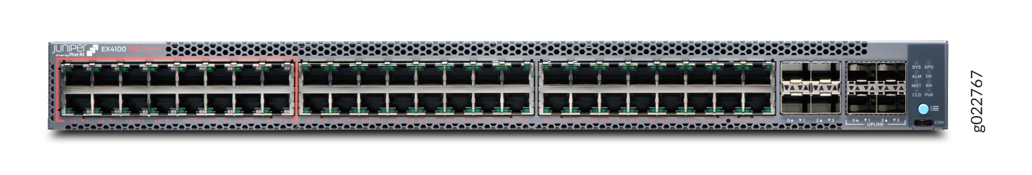
Figure 24 shows the rear view of an EX4100-48MP switch with AC power supply.
Figure 25 shows the components on the front panel of an EX4100-48MP switch.
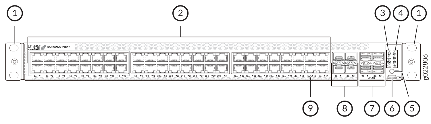
1 — Front mounting brackets | 6 — RS232 to USB Type-C console port |
2 — Sixteen 1/2.5 GE MACsec-enabled network ports. Thirty-two 1 GE BASE-T RJ-45 network ports. These ports in EX4100-48MP support PoE++ (90 W). | 7 — 1/10 GE SFP+ MACsec-enabled uplink ports |
3 — Chassis status LEDs (labeled SYS, ALM, MST, and CLD) | 8 — 10/25 GE SFP28 Virtual Chassis ports |
4 — Port mode LEDs (labeled SPD, DX, EN and PoE) | 9 — Reset button |
5 — Factory Reset/Mode button |
Figure 26 shows the components on the rear panel of an EX4100-48MP switch with an AC power supply.
1 — RJ-45 management port (labeled MGMT) | 7 — Empty slot for power supply |
2 — Claim Code label (for EX4100-MP switches) | 8 — Serial number |
3 — Fan modules | 9 — Electrostatic discharge (ESD) point |
4 — Protective earthing terminal | 10 — RJ-45 console port (labeled CON) |
5 — CLEI code label | 11 — USB 2.0 Type-A port |
6 — AC power supply |
Table 12 lists the components shipped with EX4100-48MP switch models.
Table 13 describes the physical specifications and ports of EX4100-48MP switches.
|
Model number |
Fan Modules |
Power Supply |
First Junos OS Release |
|---|---|---|---|
|
EX4100-48MP |
Two fan modules with front-to-back airflow, indicated by the label AIR OUT. |
A 920W AC power supply with the AIR OUT label. |
22.3R1 |
|
Item |
Description |
|---|---|
|
Chassis Dimensions |
Height - 1.72 in (4.37 cm) |
|
Depth - With no power supply and fan module 13.78 in (35 cm) |
|
|
Depth - With power supply and fan module installed 15.05 in (38.34 cm) |
|
|
Width—With power supply and fan module installed 17.36 in in (44.09 cm) |
|
|
Weight |
6550g - with power supply and fan module |
|
Built-in ports |
|
|
PoE Ports |
48 PoE++ (90 W) |