ON THIS PAGE
Fast Track to Rack Installation and Power
This procedure guides you through the simplest steps for the most common installation to get your EX4100 switch in a rack and connect it to power. Have more complex installation needs? See Install the EX4100 Switch
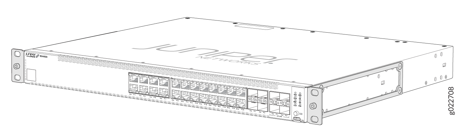
Install the EX4100 in a Rack
The mounting kit that ships in the box has the brackets you need to install the switch in a two-post rack. We’ll walk you through how to install the switch in a two-post rack. The following are instructions on how to install the EX4100 gigabit and EX4100 multigigabit switch models in a rack.
Before you install, review the following. Also, have someone available to help you secure the switch to the rack.
Place the switch on a flat, stable surface.
Wrap and fasten one end of the ESD grounding strap around your bare wrist, and connect the other end to a site ESD point.
Lift the switch and position it in the rack. Position the switch so that the AIR IN labels on the fan modules are facing the cold aisle or the AIR OUT labels on the fan modules are facing the hot aisle. Line up the bottom hole in each mounting bracket with a hole in each rack post, ensuring that the switch is level.
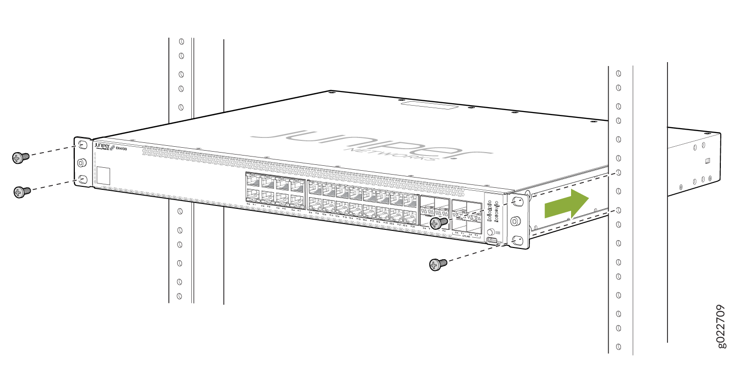
While you’re holding the switch in place, have a second person insert and tighten the rack mount screws to secure the mounting brackets to the rack posts. Tighten the screws in the two bottom holes first, and then tighten the screws in the two top holes.
Check that the mounting brackets on each side of the rack are lined up with each other.

Cover the empty extension module and the power supply slots by using the covers that came with the switch.
What's in the Box?
-
EX4100 switch with two preinstalled fan modules and one preinstalled power supply unit
-
One AC power cord appropriate for your geographical location.
-
AC power cord retainer
-
Eight preinstalled dust covers for SFP ports
-
Four rubber feet
-
RJ-45 cable and RJ-45 to DB-9 serial port adapter
What Else Do I Need?
-
Someone to help you secure the switch to the rack
-
Mounting screws to secure the switches to the rack
-
A number two Phillips (+) screwdriver
-
A serial-to-USB adapter (if your laptop doesn’t have a serial port)
-
An electrostatic discharge (ESD) grounding strap
-
A management host such as a laptop or desktop PC
-
Two M5X10mm screws with washers to secure the grounding lug
-
A grounding cable: 8 AWG (2 mm²), minimum 90° C wire, or as permitted by the local code, with a Panduit LCD8-14A-L or equivalent lug attached.
Connect to Power
To connect the EX4100 switch to AC power, you must do the following:
Ground the EX4100 Switch
To ground the EX4100 switch, do the following:
Connect one end of the grounding cable to a proper earth ground, such as the rack in which the switch is mounted.
Place the grounding lug attached to the grounding cable over the protective earthing terminal on the rear panel.
Connect a Grounding Cable to an EX4100-24P, EX4100-24T, EX4100-48P, EX4100-48T, EX4100-24MP, and EX4100-48MP Switch
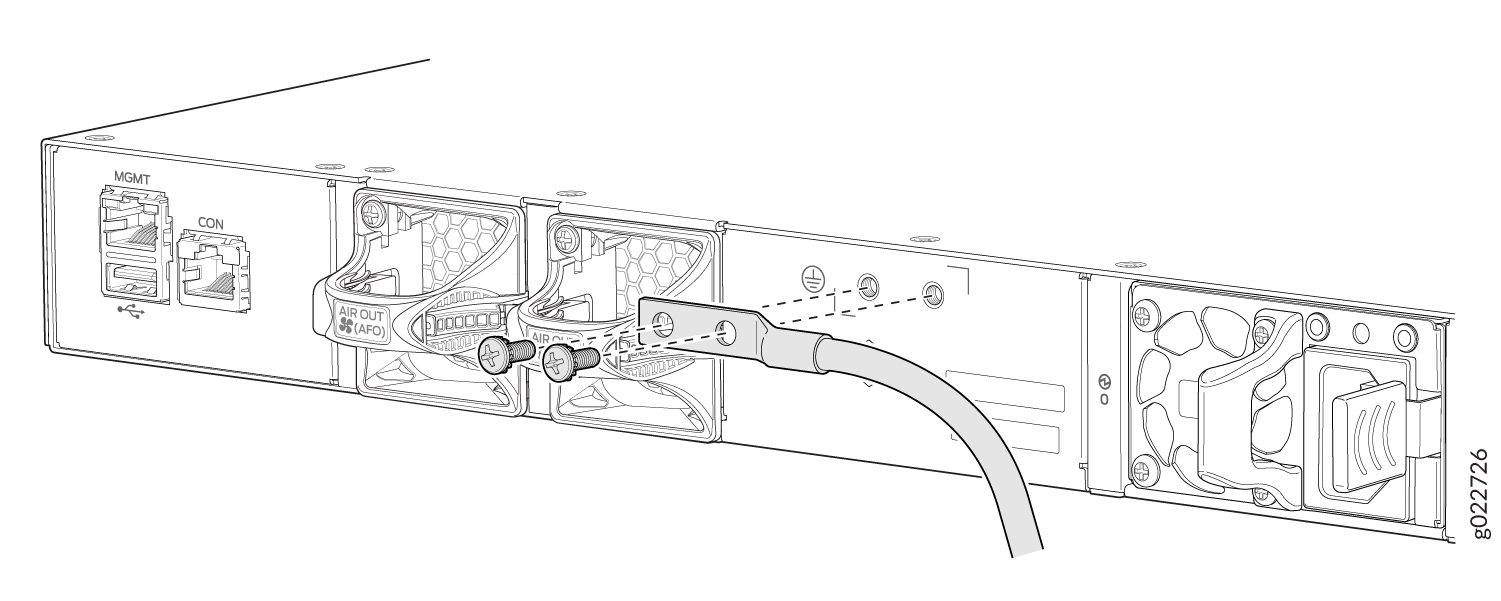
Secure the grounding lug to the protective earthing terminal with the screws.
Secure the grounding cable and ensure that it does not touch or block access to other switch components.
Connect the Power Cord and Power On the Switch
For information about the supported AC power cord specifications, see Table 7.
To connect the power cord, do the following:
Ensure that the power supply is fully inserted in the rear panel of the switch.
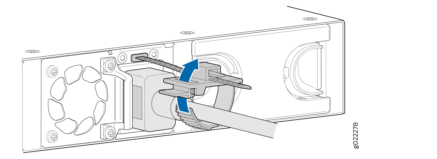
On the rear panel, connect the power cord retainer clip to the AC power supply.
Push the end of the power cord retainer strip into the slot above the power cord socket until the strip snaps into place. Ensure that the loop in the retainer strip faces the power cord. The power cord retainer clip extends out of the chassis by 3 in. (7.62 cm).
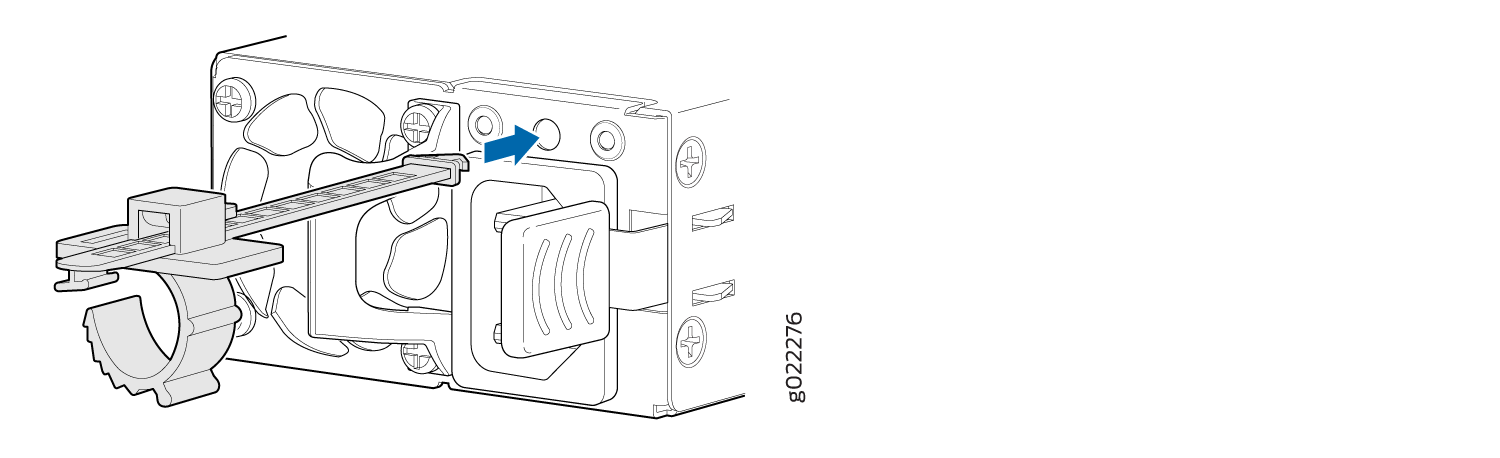
Press the small tab on the retainer strip to loosen the loop. Slide the loop until there's enough space to insert the power cord coupler into the power cord socket.
Plug in the power cord to the power cord socket.
Slide the loop toward the power supply until it's snug against the base of the coupler.
Press the tab on the loop and draw out the loop into a tight circle.
If the AC power source outlet has a power switch, turn it off.
Insert the power cord plug into an AC power source outlet.
If the AC power source outlet has a power switch, turn it on. The switch powers on as soon as you plug it in.
Check to see that the DC OK LED on the power supply is lit steadily green. If not, disconnect the power supply from the power source. You’ll need to replace the power supply (see Maintain the EX4100 Cooling System)
.