EX4100 Power System
AC Power Supply in EX4100 Switches
Juniper Networks ships EX4100 switches with one power supply installed in the rear panel. You can install up to two power supplies in an EX4100 switch. The power supply slots are numbered 0 and 1, and each slot has a power icon next to it. The power supplies support front-to-back airflow or back-to-front airflow. They are fully redundant, load-sharing, hot-removable and hot-insertable field-replaceable units (FRUs). Hot-removable and hot-insertable mean that when the second power supply is installed and running, you can remove and replace the power supplies without powering off the switch or disrupting switch functions. This topic describes the AC power supplies that EX4100 switches support.
Do not mix:
-
AC and DC power supplies in the same chassis.
-
Power supplies with different airflow directions in the same chassis.
-
Fan modules with different airflow directions in the same chassis.
-
Power supplies and fan modules with different airflow directions in the same chassis.
- Characteristics of an AC Power Supply
- Specifications of the AC Power Supplies Used in EX4100 Switches
- PoE Budget Planning
- AC Power Supply Airflow
- Specifications of the Power Cord for AC Power Supplies for EX4100 Switches
Characteristics of an AC Power Supply
The AC power supplies for EX4100 switches are field-replaceable units (FRUs).
-
The EX4100-24P and EX4100-48P switches use 920-W power supplies. The AC power supplies support Power over Ethernet (PoE+) in EX4100-24P and EX4100-48P switch models.
-
The EX4100-24MP and EX4100-48MP switches use 920-W power supplies. The AC power supplies support Power over Ethernet (PoE++) in EX4100-24MP and EX4100-48MP switch models.
-
The EX4100-24T, EX4100-48T, and EX4100-48T-AFI switches use 150-W power supplies.
Refer EX4100 Power System to check which EX4100 models use which PSUs or built-in power supplies.
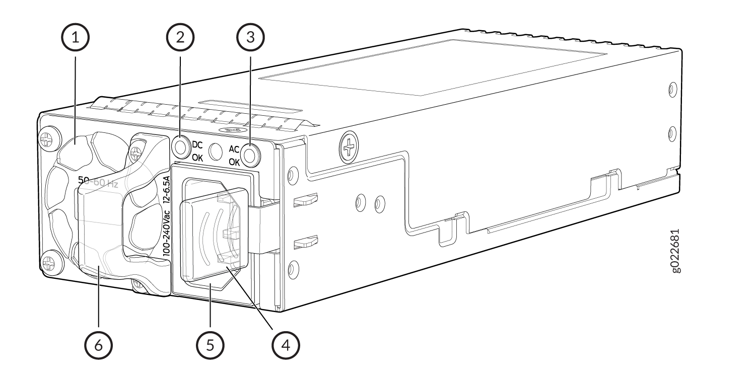
1 — Power Supply Unit Fan | 4 — Power Supply Unit ejector lever |
2 — Power Supply Unit DC LED | 5 — Power Supply Unit inlet |
3 — Power Supply Unit AC LED | 6 — Power Supply Unit handle |
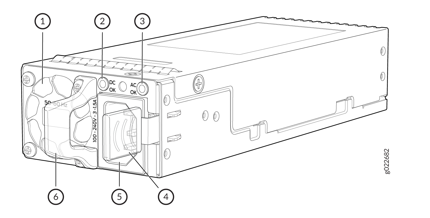
1 — Power Supply Unit fan | 4 — Power Supply Unit ejector lever |
2 — Power Supply Unit DC LED | 5 — Power Supply Unit inlet |
3 — Power Supply Unit AC LED | 6 — Power Supply Unit handle |
Table 1 lists details of the 920 W, 150 W AC power supplies used in EX4100 switches.
|
Details |
920 W AC Power Supply |
150 W AC Power Supply |
|
|---|---|---|---|
|
Model number |
|
|
|
|
Minimum installed in chassis |
1 |
1 |
|
|
Maximum installed in chassis |
2 |
2 |
|
|
AC appliance inlet Note:
Each AC appliance inlet requires a dedicated AC power source. |
Number |
1 |
1 |
|
Type |
I |
||
|
Power supply status LEDs |
AC OK and DC OK |
AC OK and DC OK |
|
To prevent electrical injury while installing or removing AC power supplies, carefully follow instructions in Install an AC Power Supply in an EX4100 Switch and Remove an AC Power Supply from an EX4100 Switch.
Specifications of the AC Power Supplies Used in EX4100 Switches
-
Table 2 provides the power supply specifications of the 920 W AC power supplies.
-
Table 3 provides the power supply specifications of the 150 W AC power supplies.
|
Item |
Specification |
|---|---|
|
AC input voltage |
|
|
AC input line frequency |
50–60 Hz |
|
AC input current rating |
|
|
Output power |
920 W |
|
Item |
Specification |
|---|---|
|
AC input voltage |
|
|
AC input line frequency |
50–60 Hz |
|
AC input current rating |
|
|
Output power |
150 W |
PoE Budget Planning
Table 4 shows the PoE budget planning details in EX4100-24P and EX4100-48P switch models. Table 5 shows the PoE budget planning details in EX4100-24MP and EX4100-48MP switches.
|
Model |
System Budget |
PoE Budget |
Total Budget |
Total PSU power |
|---|---|---|---|---|
|
48P one PSU |
106 W |
740 W |
846 W |
920 W |
|
48P two PSU |
106 W |
1440 W |
1546 W |
1840 W |
|
24P one PSU |
93 W |
740 W |
833 W |
920 W |
|
24P two PSU |
93 W |
1440 W |
1533 W |
1840 W |
|
Model |
System Budget |
PoE Budget |
Total Budget |
Total PSU power |
|---|---|---|---|---|
|
48MP one PSU |
140 W |
740 W |
880 W |
920 W |
|
48MP two PSU |
140 W |
1620 W |
1760 W |
1840 W |
|
24MP one PSU |
129 W |
740 W |
869 W |
920 W |
|
24MP two PSU |
129 W |
1620 W |
1749 W |
1840 W |
Apart from the aforementioned combinations, any other combination will be insufficient to power the switch.
AC Power Supply Airflow
Each power supply has its own fan and is cooled by its own internal cooling system. Each power supply has a label AIR OUT or AIR IN on the faceplate of the power supply. The label indicates the direction of airflow in the power supply. Table 6 lists the AC power supply models and the direction of airflow in them.
|
Model |
Label on Power Supply |
Direction of Airflow |
|---|---|---|
|
AIR OUT |
Front to back. Air to cool the chassis enters through the vents on the front panel of the chassis. Hot air exits through the vents on the rear panel of the chassis. |
|
AIR IN |
Back to front. Air to cool the chassis enters through the vents on the rear panel of the chassis. Hot air exits through the vents on the front panel of the chassis. |
Specifications of the Power Cord for AC Power Supplies for EX4100 Switches
A detachable AC power cord is supplied with the AC power supplies. The coupler is type C13 as described by International Electrotechnical Commission (IEC) standard 60320. The plug end of the power cord fits into the power source outlet that is standard for your geographical location.
The AC power cord provided with each power supply is intended for use with that power supply only and not for any other use.
In North America, AC power cords must not exceed 4.5 meters (approximately 14.75 feet) in length, to comply with National Electrical Code (NEC) Sections 400-8 (NFPA 75, 5-2.2) and 210-52 and with Canadian Electrical Code (CEC) Section 4-010(3). The cords supplied with the switch are in compliance.
Table 7 gives the AC power cord specifications for the countries and regions listed in the table.
|
Country or Region |
Electrical Specifications |
Plug Standards |
Juniper Model Number |
|---|---|---|---|
|
Argentina |
250 VAC, 10 A, 50 Hz |
IRAM 2073 Type RA/3 |
CBL-EX-PWR-C13-AR |
|
Australia |
250 VAC, 10 A, 50 Hz |
AS/NZZS 3112 Type SAA/3 |
CBL-EX-PWR-C13-AU |
|
Brazil |
250 VAC, 10 A, 50 Hz |
NBR 14136 Type BR/3 |
CBL-EX-PWR-C13-BR |
|
China |
250 VAC, 10 A, 50 Hz |
GB 1002-1996 Type PRC/3 |
CBL-EX-PWR-C13-CH |
|
Europe (except Italy, Switzerland, and the United Kingdom) |
250 VAC, 10 A, 50 Hz |
CEE (7) VII Type VIIG |
CBL-EX-PWR-C13-EU |
|
India |
250 VAC, 10 A, 50 Hz |
IS 1293 Type IND/3 |
CBL-EX-PWR-C13-IN |
|
Israel |
250 VAC, 10 A, 50 Hz |
SI 32/1971 Type IL/3G |
CBL-EX-PWR-C13-IL |
|
Italy |
250 VAC, 10 A, 50 Hz |
CEI 23-16 Type I/3G |
CBL-EX-PWR-C13-IT |
|
Japan |
125 VAC, 12 A, 50 Hz or 60 Hz |
JIS 8303 |
CBL-EX-PWR-C13-JP |
|
Korea |
250 VAC, 10 A, 50 Hz or 60 Hz |
CEE (7) VII Type VIIGK |
CBL-EX-PWR-C13-KR |
|
North America* |
125 VAC, 13 A, 60 Hz |
NEMA 5-15 Type N5-15 |
CBL-EX-PWR-C13-US |
|
125 VAC, 15 A, 60 Hz |
NEMA 5-15 Type N5-15 |
CBL-PWR-C13-US-48P |
|
|
South Africa |
250 VAC, 10 A, 50 Hz |
SABS 164/1:1992 Type ZA/13 |
CBL-EX-PWR-C13-SA |
|
Switzerland |
250 VAC, 10 A, 50 Hz |
SEV 6534-2 Type 12G |
CBL-EX-PWR-C13-SZ |
|
United Kingdom |
250 VAC, 10 A, 50 Hz |
BS 1363/A Type BS89/13 |
CBL-EX-PWR-C13-UK |
For North America, use AC power cords with specifications 125 VAC, 13 A, 60 Hz for EX4100-24T and EX4100-48T.
Figure 3 illustrates the plug on the power cord for some of the countries or regions listed in Table 7.
Do not use the AC power cord with any other product other than EX4100.
Power cords must not block access to switch components.
Table 8 lists the specifications of the power cords used to connect EX4100 switches to C13 Power Strips.
|
Country/Region |
Electrical Specifications |
Juniper Model Number |
|---|---|---|
|
USA, China, Japan, Europe, South Korea, Australia |
250 VAC, 10 A, 50 Hz |
CBL-EX-PWR-C13-C14 |
DC Power Supply in EX4100 Switches
EX4100 switches are shipped with one power supply installed in the rear panel of the switches. You can install up to two power supplies in an EX4100 switch. The power supply slots are numbered 0 and 1, and each slot has a power icon next to it. The power supplies support front-to-back airflow directions and are fully redundant, load-sharing, hot-removable and hot-insertable field-replaceable units (FRUs) when the second power supply is installed and running: You can remove and replace them without powering off the switch or disrupting switch functions. This topic describes the DC power supplies that EX4100 switches support.
Do not mix:
-
AC and DC power supplies in the same chassis.
-
Power supplies with different airflow directions in the same chassis.
-
Fan modules with different airflow directions in the same chassis.
-
Power supplies and fan modules with different airflow directions in the same chassis.
- Characteristics of a DC Power Supply
- Specifications of the DC Power Supplies Used in EX4100 Switches
- DC Power Supply Airflow
Characteristics of a DC Power Supply
The DC power supplies for EX4100 switches are available in 150 W model. EX4100-48T-DC, EX4100-24T-DC support 150 W DC power supplies. You can install up to two DC power supplies in an EX4100 switch. Power supplies are installed in the power supply slots labeled PSU 0 and PSU 1 in the rear panel of the chassis.
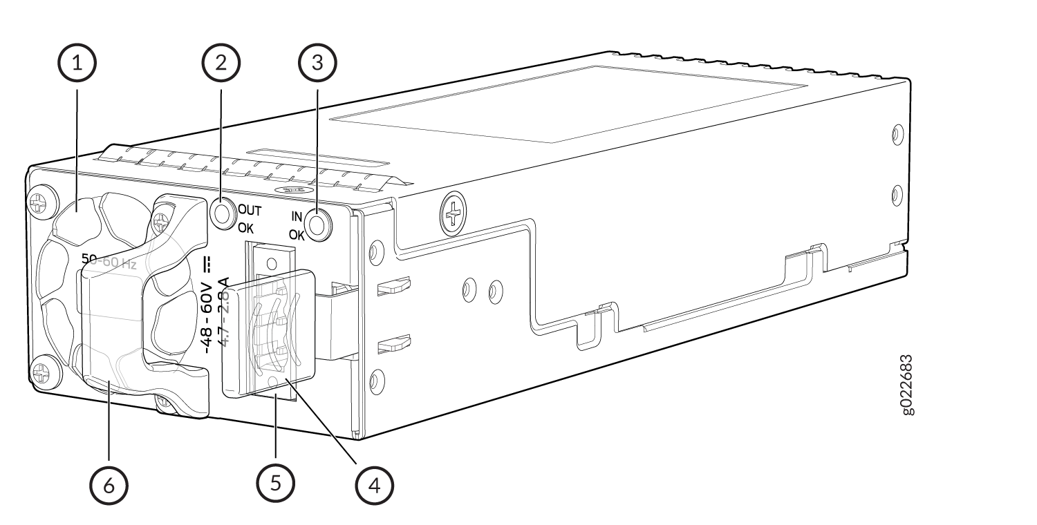
1 — Power supply unit fan | 4 — Power supply unit ejector lever |
2 — Power supply unit LED | 5 — Power supply unit inlet |
3 — Power supply unit LED | 6 — Power supply unit handle |
Table 9 lists the details of the 150 W DC power supplies used in EX4100 switches.
|
Details |
150 W DC Power Supplies |
|
|---|---|---|
|
Model number |
JPSU-150-DC-AFO |
|
|
Minimum number of power supplies installed in chassis |
1 |
|
|
Maximum number of power supplies installed in chassis |
2 |
|
|
Power supply status LEDs |
IN OK and OUT OK |
|
To prevent electrical injury while installing or removing DC power supplies, carefully follow instructions in Install a DC Power Supply in an EX4100 Switch and Remove a DC Power Supply from an EX4100 Switch.
Specifications of the DC Power Supplies Used in EX4100 Switches
Table 10 provides the power supply specifications of the 150 W DC power supplies.
|
Item |
Specification |
|---|---|
|
DC input voltage |
Rated operating voltage: –48 VDC to –60 VDC |
|
DC input current rating |
4.7A - 2.8 A |
|
Output power |
150 W |
DC Power Supply Airflow
Each power supply has its own fan and internal cooling system. Each power supply has a label AIR OUT or AIR IN on the faceplate of the power supply that indicates the direction of airflow through the power supply. Table 11 lists the DC power supply models and the direction of airflow throughthem.
|
Model |
Label on Power Supply |
Direction of Airflow |
|---|---|---|
|
JPSU-150-DC-AFO |
AIR OUT |
Front to back: Air to cool the chassis enters through the vents on the front panel of the chassis. Hot air exits through the vents on the rear panel of the chassis. |
Power Supply LEDs in EX4100 Switches
The power supply for EX4100 switches have one LED that indicates the state of the power supply (see Figure 5 and Figure 6).
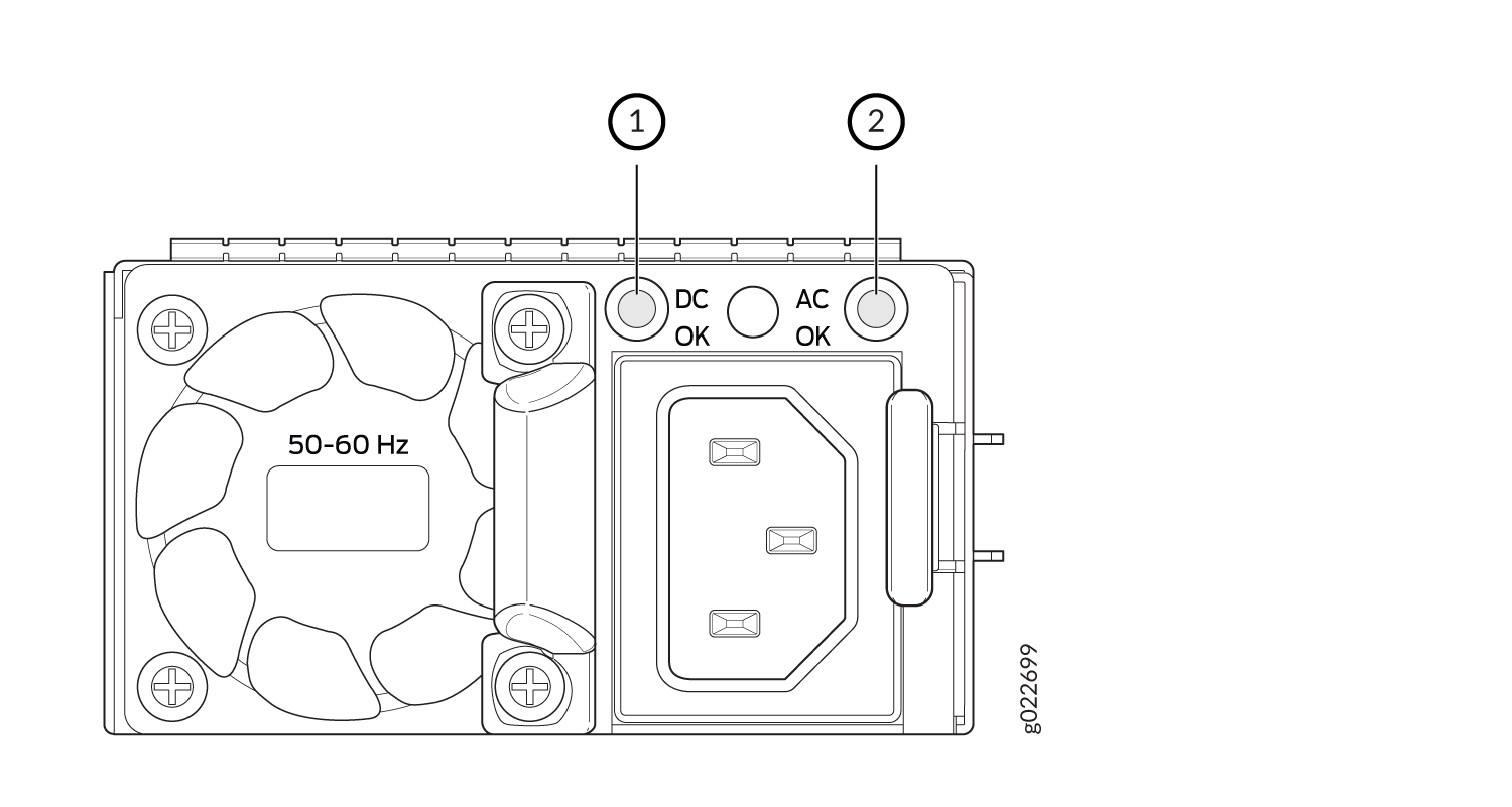
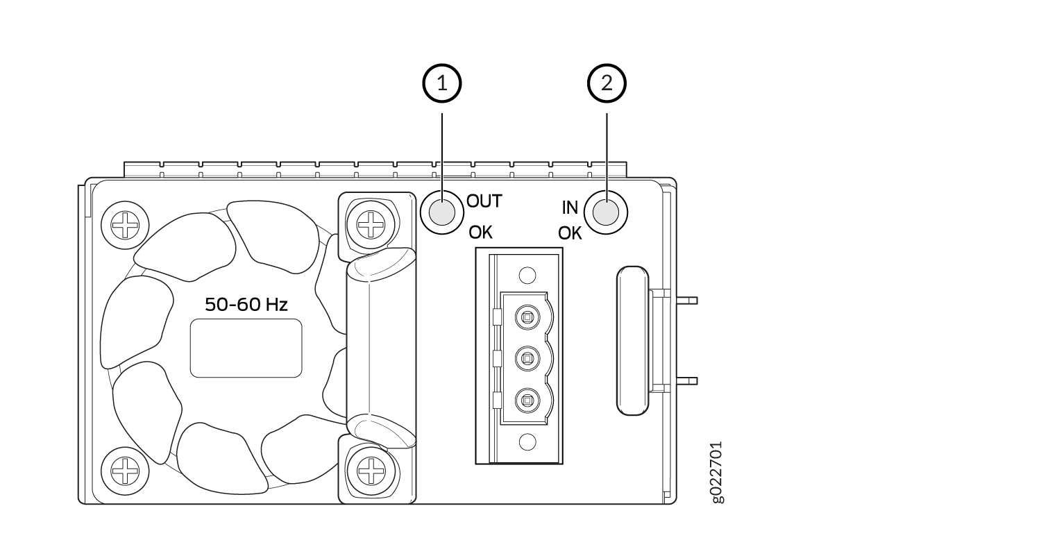
Table 12 describes the AC power supply LEDs.
|
LED |
Color |
Description |
|---|---|---|
|
AC OK |
Unlit |
Indicates one of the following:
|
|
Green |
The power supply is receiving proper input power. |
|
|
Red |
The power supply has failed. |
|
|
Flashing Red |
This PSU is not receiving power. |
|
|
DC OK |
Unlit |
Indicates one of the following:
|
|
Green |
The power supply is delivering power and is functioning correctly. |
|
|
Red |
The power supply has failed. |
|
|
Flashing red |
This PSU is not receiving power. |
If the AC OK LED and the DC OK LED are not lit green, either the AC power cord is not installed properly or the power input voltage is not within normal operating range.
If the AC OK LED is lit green and the DC OK LED is unlit or lit red, the AC power supply is installed properly, but the power supply has an internal failure.
Table 13 describes the LEDs on the DC power supplies.
|
Name |
Color |
Description |
|---|---|---|
|
IN OK |
Unlit |
Indicates one of the following:
|
|
Green |
The power supply is receiving power. |
|
|
Red |
The power supply has failed. |
|
|
Flashing Red |
This PSU is not receiving power. |
|
|
OUT OK |
Unlit |
Indicates one of the following:
|
|
Green |
The power supply is functioning correctly. |
|
|
Red |
The power supply has failed and must be replaced. |
|
|
Flashing red |
This PSU is not receiving power. |