ON THIS PAGE
Mount an EX4100-H-12MP Switch Using Rack Mount Kit (with DIN Rail) Within a Cabinet
Mount an EX4100-H-12MP Switch Using Rack Mount Kit (Screw Mount) Within a Cabinet
Mount an EX4100-H-12MP Switch on a Ferrous Wall or Surface Using Magnet Pads Within a Cabinet
Mount an EX4100-H-12MP Switch in a Desktop Orientation or on a Flat Surface Within a Cabinet
Mount an EX4100-H-12MP Switch Using DIN Rail Mount Kit Within a Cabinet
Unmounting an EX4100-H-12MP Switch from a DIN Rail Within a Cabinet
Mount an EX4100-H-24MP or EX4100-H-24F Switch in a Rack Within a Cabinet
Attaching the Physical Security Lock to the EX4100-H-12MP Switch
Attaching the Physical Security Lock to the EX4100-H-24MP and EX4100-H-24F Switch
Install the EX4100-H Switch
This topic guides you through the steps to install EX4100-H switches.
Unpack the EX4100-H Switch
We ship the EX4100-H switches in a cardboard carton, secured with foam packing material. The carton has an accessory compartment.
The shipping carton completely protects the EX4100-H switches. Leave the switches safely in the carton until you are ready to begin installation.
To unpack the switch:
- Move the shipping carton to a staging area as close to the installation site as possible, but where you have enough room to remove the system components.
- Position the carton so that the arrows are pointing up.
- Open the top flaps on the shipping carton.
- Pull out the packing material holding the switch in place.
- Verify the parts received against the inventory on the label attached to the carton (see Packing List for an EX4100-H Switch).
- Save the shipping carton and packing materials in case you need to move or ship the switch later.
Packing List for an EX4100-H Switch
The switch shipment includes a packing list. Check the parts you receive with the switch against the items on the packing list. The packing list specifies the part number and provides a description of each part in your order. The parts shipped match the switch model you ordered (see EX4100-H Models and Specifications).
If any part on the packing list is missing, contact your customer service representative or contact Juniper customer care from within the U.S. or Canada by telephone at 1-888-314-5822. For international-dial or direct-dial options in countries without toll-free numbers, see https://www.juniper.net/support/requesting-support.html.
-
Table 1 provides details on inventory of components provided with the EX4100-H-12MP switch models.
-
Table 2 provides details on inventory of components provided with the EX4100-H-24MP switch models.
-
Table 3 provides details on inventory of components provided with the EX4100-H-24F switch models.
|
Component |
Quantity |
|
|---|---|---|
|
Switch |
1 |
|
|
Power supply unit |
1 (specific to the switch—AC or DC) |
|
|
AC power cord appropriate for your geographical location |
1 |
|
|
Cable between the switch and the PSU |
1 |
|
|
DC cable |
1 (not shipped with AC SKUs) |
|
|
Dust covers |
20 (preassembled): SFP (4), RJ45 (14), USB-A (1), USB-C (1) |
|
|
Alarm connector |
1 (preassembled to switch) |
|
|
PSU terminal connectors |
2 (preassembled to switch) |
|
|
Documentation roadmap/warranty card |
1 |
|
|
Juniper Networks Product Warranty |
1 |
|
|
End User License Agreement |
1 |
|
|
Component |
Quantity |
|
|---|---|---|
|
Switch |
1 |
|
|
Power supply unit |
1 (specific to the switch—AC or DC pre-assembled to the switch) |
|
|
AC Power Cord |
1 (Shipped with AC SKU), specific to region |
|
|
DC cable (shipped with DC SKU) |
1 (Shipped with DC SKU), not shipped with AC SKUs |
|
|
Dust covers: |
36 (preassembled): SFP (8), RJ45 (26), USB-A (1), USB-C (1) |
|
|
Alarm connector |
1 (preassembled to switch) |
|
|
Rack Mounting Kit |
1 |
|
|
Documentation Roadmap/Warranty Card/End User License Agreement |
1 |
|
|
Component |
Quantity |
|
|---|---|---|
|
Switch |
1 |
|
|
Power supply unit |
1 (specific to the switch—AC or DC pre-assembled to the switch) |
|
|
AC Power Cord |
1 (Shipped with AC SKU), specific to region |
|
|
DC cable (shipped with DC SKU) |
1 (Shipped with DC SKU), not shipped with AC SKUs |
|
|
Dust covers |
20 (preassembled): SFP (32), RJ45 (2), USB-A (1), USB-C (1) |
|
|
Alarm connector |
1 (preassembled to switch) |
|
|
Rack Mounting Kit |
1 |
|
|
Documentation Roadmap/Warranty Card/End User License Agreement |
1 |
|
For all mounting options:
The EX4100-H switch (with PSU if using external PSU or with PSU FRU) must be installed in a certified cabinet or enclosure to prevent any personal injury due to access to live parts. The enclosure shall be accessible by using a tool. The access to the switch shall be restricted. Only instructed and skilled person must access the switch. This requirement applies to any off-the-shelf external PSU as well.
For traffic control application (NEMA TS2), the EX4100-H switch must be installed in a NEMA 4 certified cabinet or certified enclosure as per NEMA TS2 standard ( section 7 requirement). The cabinet shall meet the NEMA TS2 section 7 requirement.
EX4100-H with all types of mounting (wall, desk, magnet, rack, and Din) must be installed in a certified cabinet.
The certified cabinet or enclosure must meet the fire enclosure requirements of UL, EN 62368-1 to ensure no foreign objects fall into the switch (and PSU if using external PSU) and no flaming particles fall out from the switch (and PSU if using external PSU) to outside.
User shall assess the climatic/environmental conditions at installation site to select the cabinet/enclosure to ensure that the switch (and PSU if using external PSU) is protected from dust, rain, salt fog, pollutants to prevent any damage. Below are few examples.
For indoor and indoor non office installation with very low dust/moisture – certified sealed cabinet/enclosure must be certified to minimum IP 54 (defined in EN60529) or certified TYPE 4 (defined in UL 50).
For installing the switch (and PSU if using external PSU) in outdoor environment (to protect from dust, corrosion, moisture, salt fog, pollutants, rain) sealed enclosure or certified sealed cabinet must be certified to IP65 or higher (IP code defined in EN 60529) or TYPE 4 (defined in UL 50E, UL50)
When using the external PSU DDR-120B-12 with the EX4100-H-12MP switch, ensure that the input of the DDR-120B-12 PSU is connected to a DC power source that is isolated from the mains.
Update Base Installation Data
Update the installation base data if any addition or change to the installation base occurs or if the installation base is moved. Juniper Networks is not responsible for not meeting the hardware replacement SLA for products that do not have accurate installation base data.
Update your installation base at https://supportportal.juniper.net/s/CreateCase .
Mount an EX4100-H-12MP Switch Using Rack Mount Kit (with DIN Rail) Within a Cabinet
Before mounting the switch using rack mount kit (with DIN Rail) within a cabinet:
-
Verify that the site meets the requirements described in Environmental Requirements and Specifications for EX4100-H Switches.
-
Place the rack in its permanent location, allowing adequate clearance for airflow and maintenance, and secure it to the building structure.
-
Read General Safety Guidelines and Warnings, with particular attention to Chassis and Component Lifting Guidelines .
Ensure that you have the following parts and tools available:
-
Rack mounting bracket with DIN rail channel (EX4100-H-12-RM-DRK)
-
DIN rail kit
-
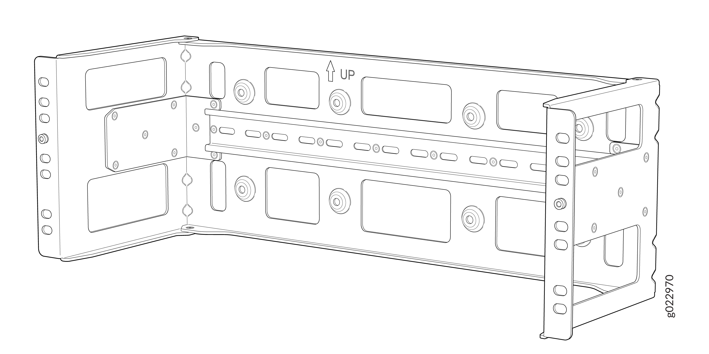
The rack mounting bracket with DIN Rail channel is attached to the two-post
rack for mounting the EX4100-H-12MP switch and PSU within a cabinet. The
following is the figure of the rack mounting bracket with DIN Rail
channel.
Note: Recommended torque for mounting bracket to the switch and PSU:22 +/- 0.5 Lb.inFigure 1: Rack Mounting Bracket with DIN Rail Channel
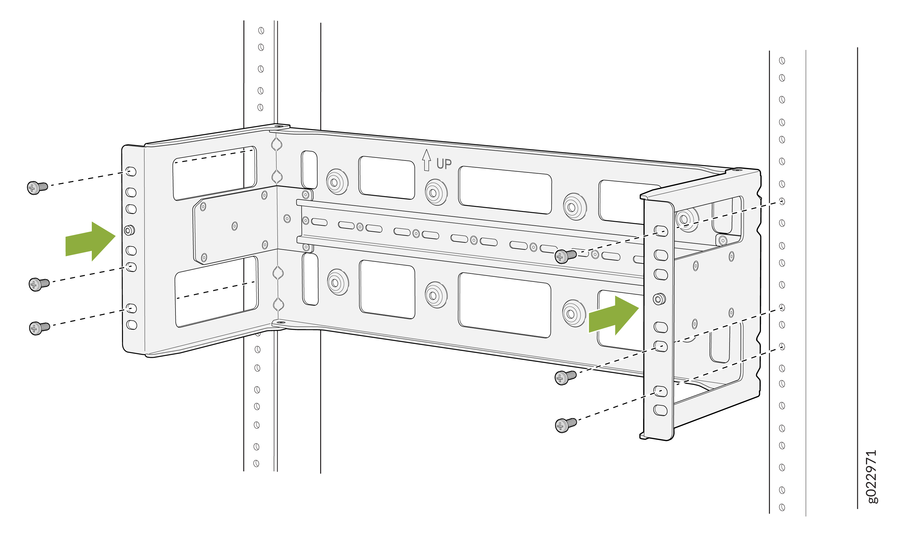
-
Attach the rack mounting bracket with DIN Rail channel to the two-post
rack.
Figure 2: Attach rack mounting bracket with DIN Rail channel to the two-post rack
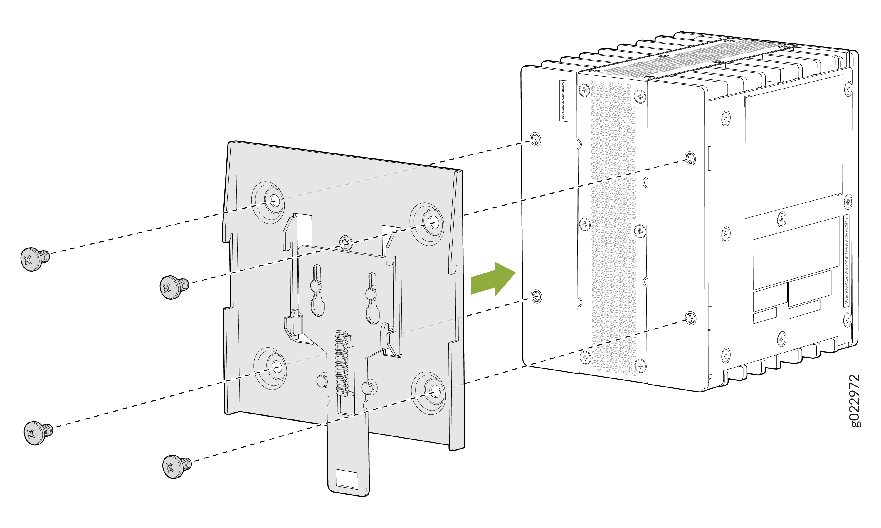
-
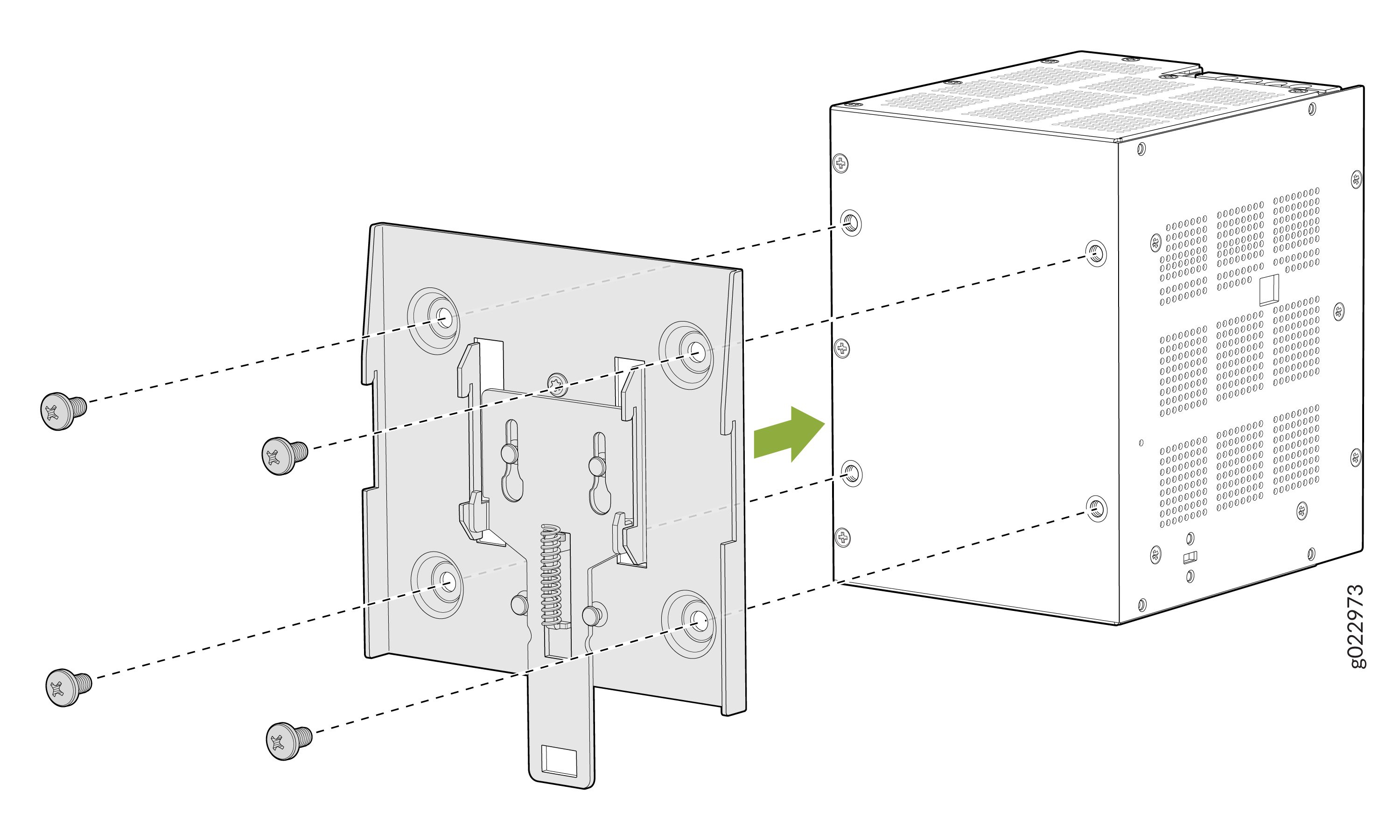
Attach the DIN Rail bracket to the switch.
Figure 3: Attach DIN Rail bracket to the switch
-
Attach the DIN Rail bracket to the PSU.
Figure 4: Attach DIN Rail bracket to the PSU
-
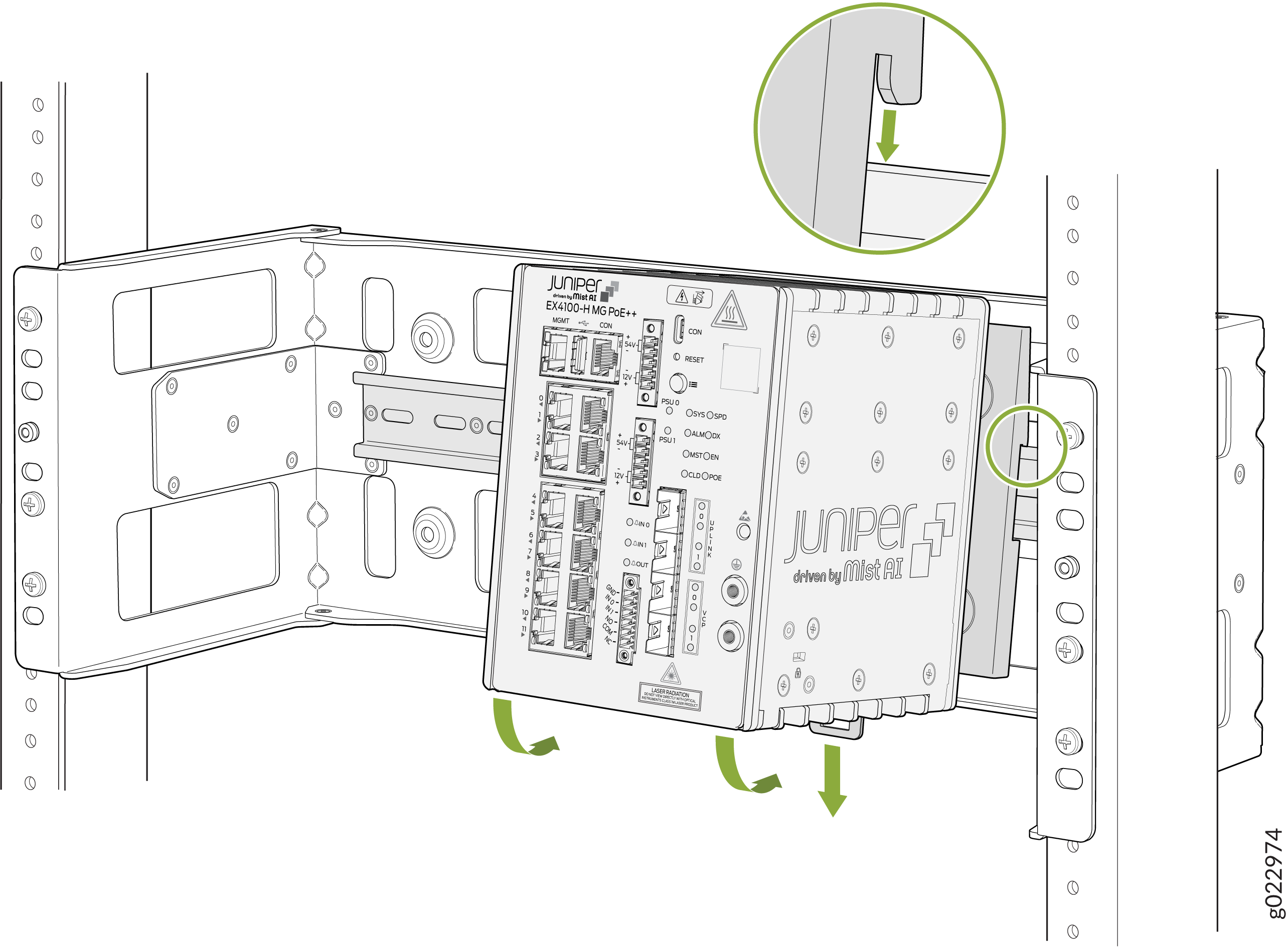
Mount the switch to the DIN Rail channel of the rack mounting
bracket.
Figure 5: Mount switch to DIN Rail channel
-
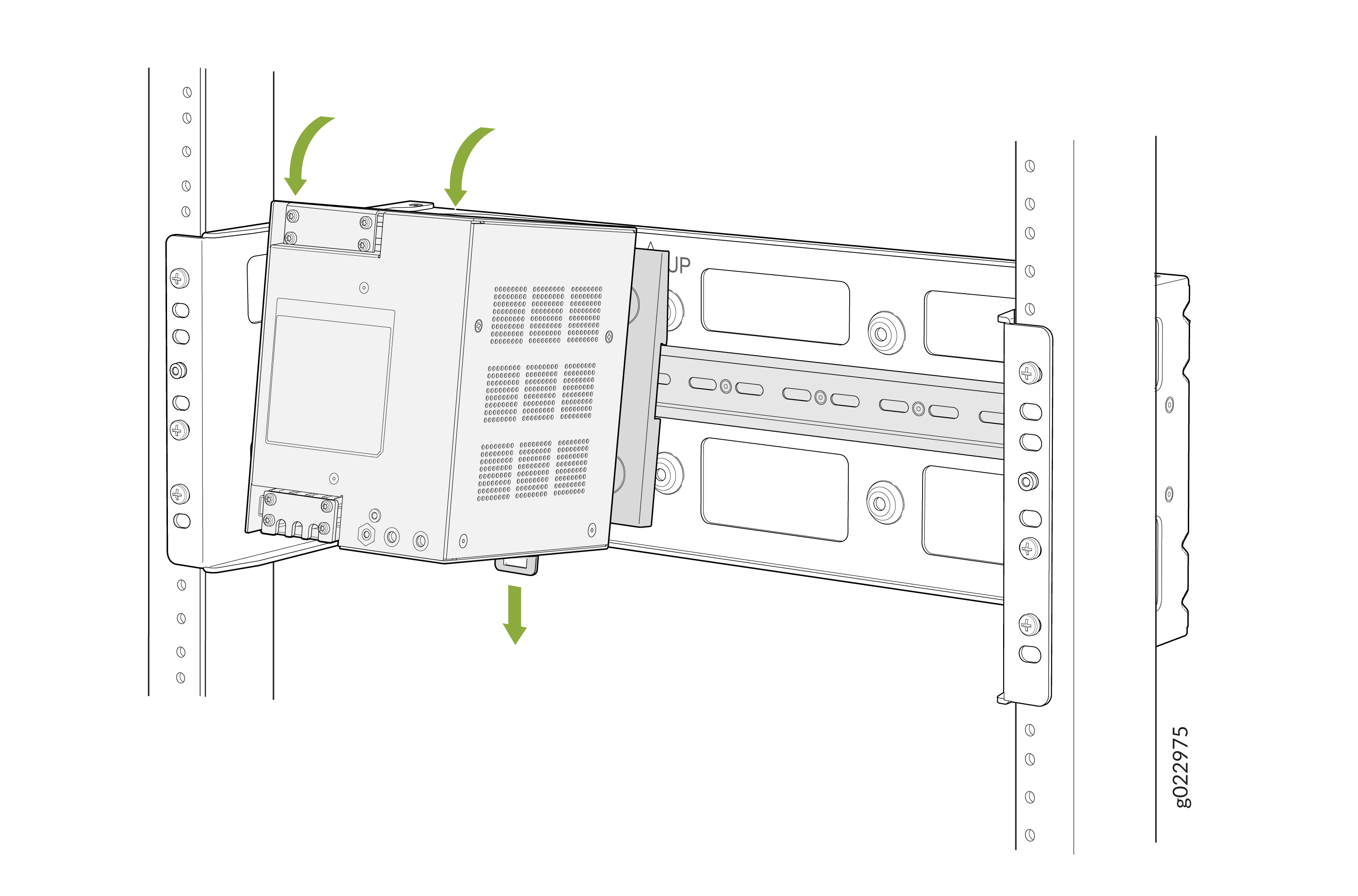
Mount the PSU to the DIN Rail channel of the rack mounting bracket.
Figure 6: Mount PSU to DIN Rail channel
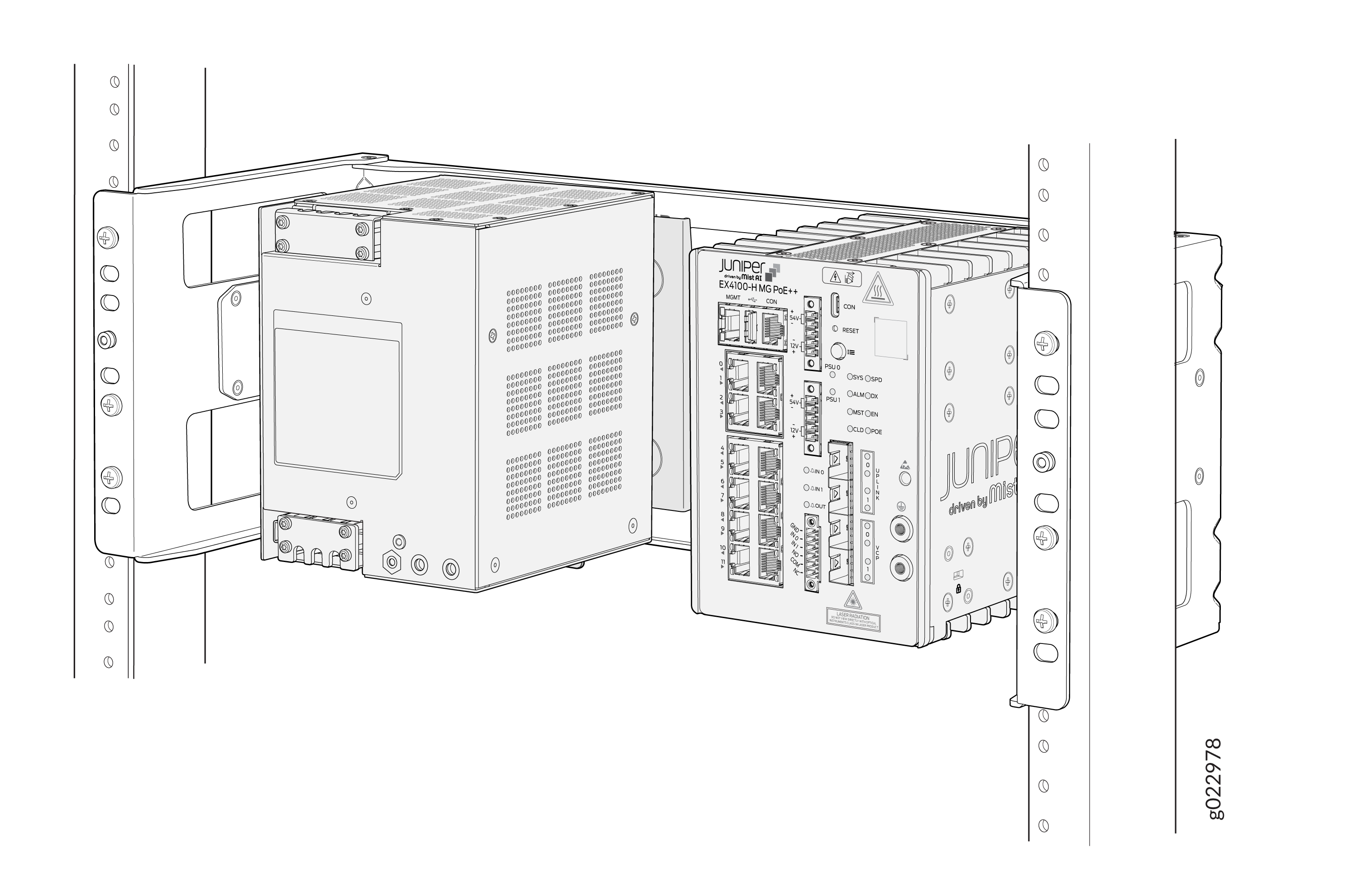
-
You have mounted the EX4100-H-12MP switch and PSU to the DIN Rail channel
of the rack mounting bracket that is attached to the two-post mounting rack
within a cabinet.
Figure 7: Switch and PSU Mounted using DIN Rail channel of the rack mounting bracket in the two-post rack within a cabinet
Mount an EX4100-H-12MP Switch Using Rack Mount Kit (Screw Mount) Within a Cabinet
Before mounting the switch in a rack:
-
Verify that the site meets the requirements described in Environmental Requirements and Specifications for EX4100-H Switches.
-
Place the rack in its permanent location, allowing adequate clearance for airflow and maintenance, and secure it to the building structure.
-
Read General Safety Guidelines and Warnings, with particular attention to Chassis and Component Lifting Guidelines .
Ensure that you have the following parts and tools available:
-
One rack mounting bracket
-
Eight M5 L8 screws
-
An EX4100-H-12-RMK kit
-
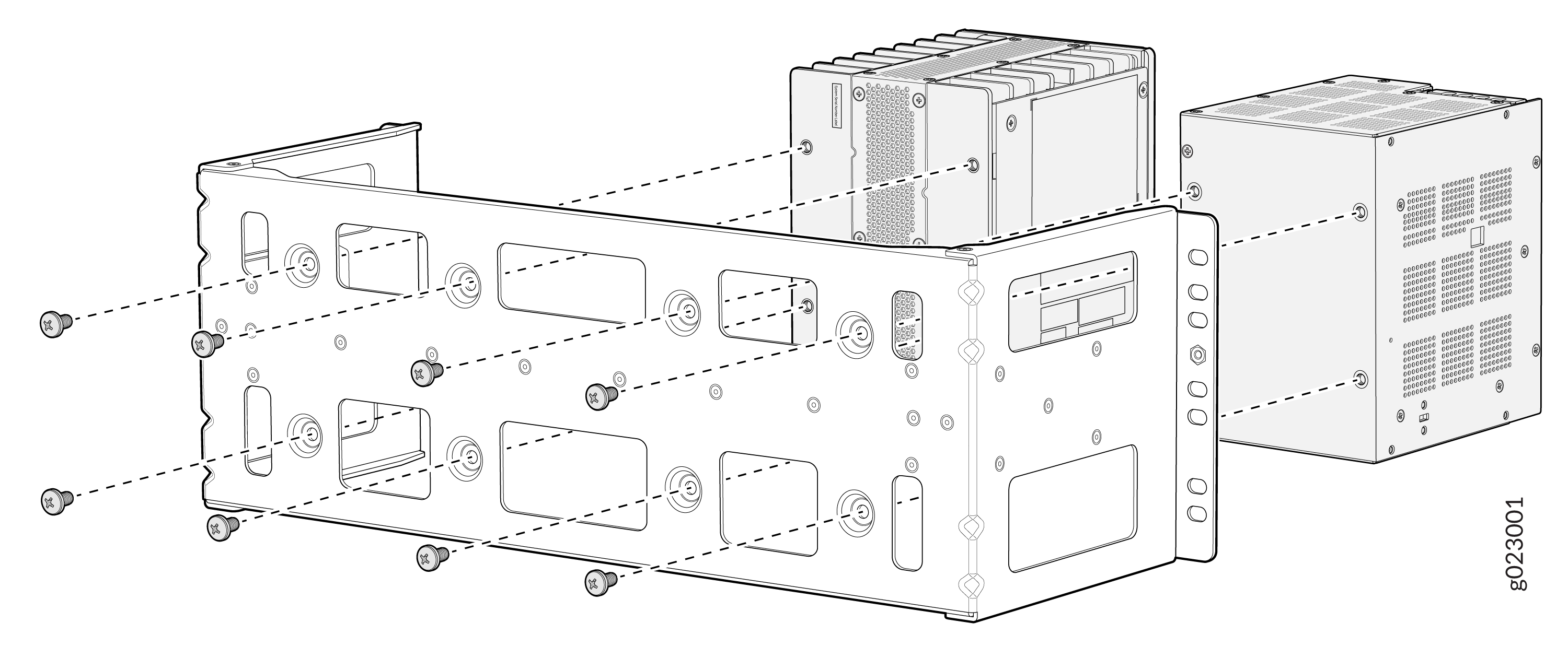
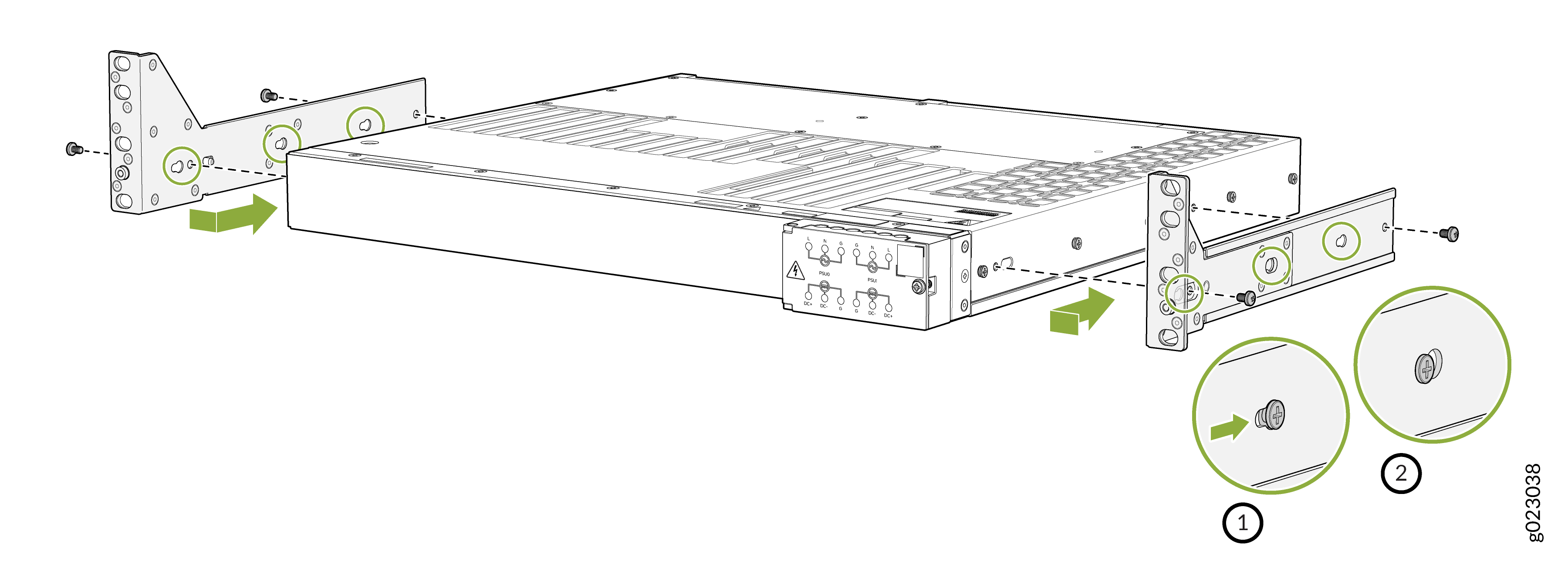
Assemble the PSU and switch to the rack mounting bracket by using M5 L8
screws.
Note: Recommended torque for mounting bracket to the switch and PSU:22 +/- 0.5 Lb.inFigure 8: Assemble the PSU and Switch to the rack mounting bracket with screws
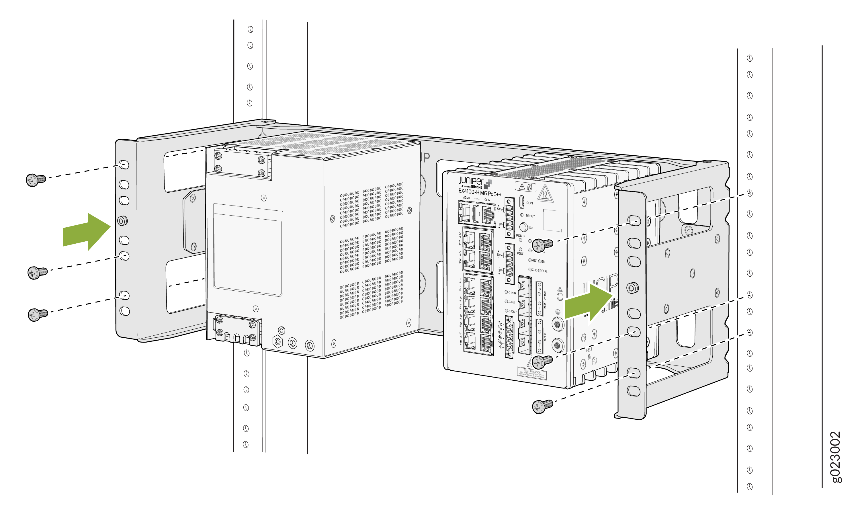
-
Attach the rack mounting bracket to the two-post rack within a
cabinet.
Figure 9: Attach the rack mounting bracket to the rack
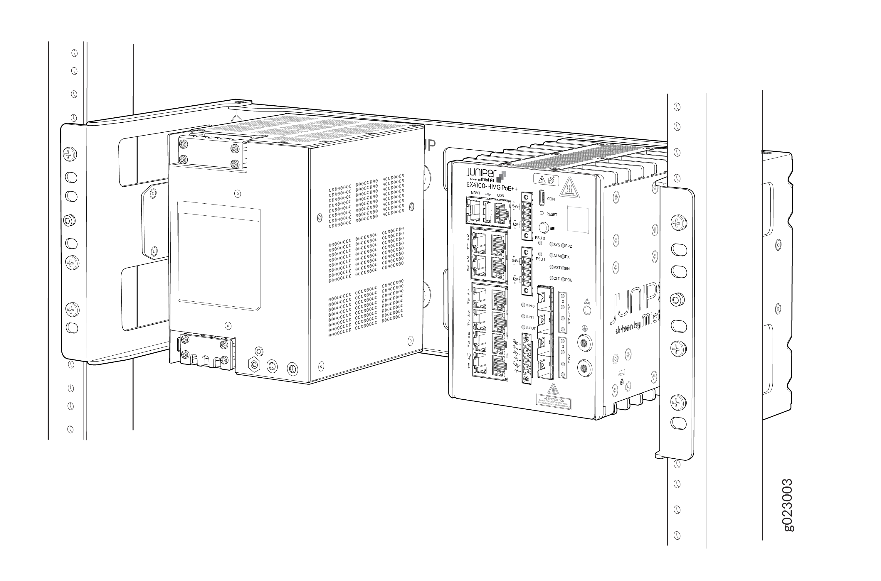
-
The switch and the PSU mounted to the rack mounting bracket that is
attached to the two-post rack within cabinet.
Figure 10: The Switch and the PSU mounted to the rack mounting bracket
Mount an EX4100-H-12MP Switch on a Ferrous Wall or Surface Using Magnet Pads Within a Cabinet
Before mounting the switch on a wall. ensure that you have the following parts and tools available:
-
Two magnet support plates(one for the switch and the other for the PSU)
-
Eight M5 L8 screws
-
Two magnet pads
Magnet mounting is to be done within the building only, not to be installed outside of building. Switch and PSU has to be mounted in a location where there is no direct sunlight on the switch and PSU. Switch and PSU should not be installed near to heat source as the temperature affects magnet performance.
If you do not install the magnet and the device correctly, it could lead to a hazard. Use only the magnet kit provided by Juniper to mount your device. You can mount the switches on a ferrous wall in IT or secure room using magnet pads.
-
You can mount the units on a ferrous wall using magnet pads, at a height of no more than 2 m.
-
Make sure the ferrous wall is smooth and free of any contaminants like oil, grease, dirt, etc., as otherwise the unit may fall.
-
Ensure that the ferrous wall on which the switch is mounted isn’t close to any area where any vibration or impact may occur. Also, you must not mount the product near any heat-generating area as it can cause the mounting to malfunction.
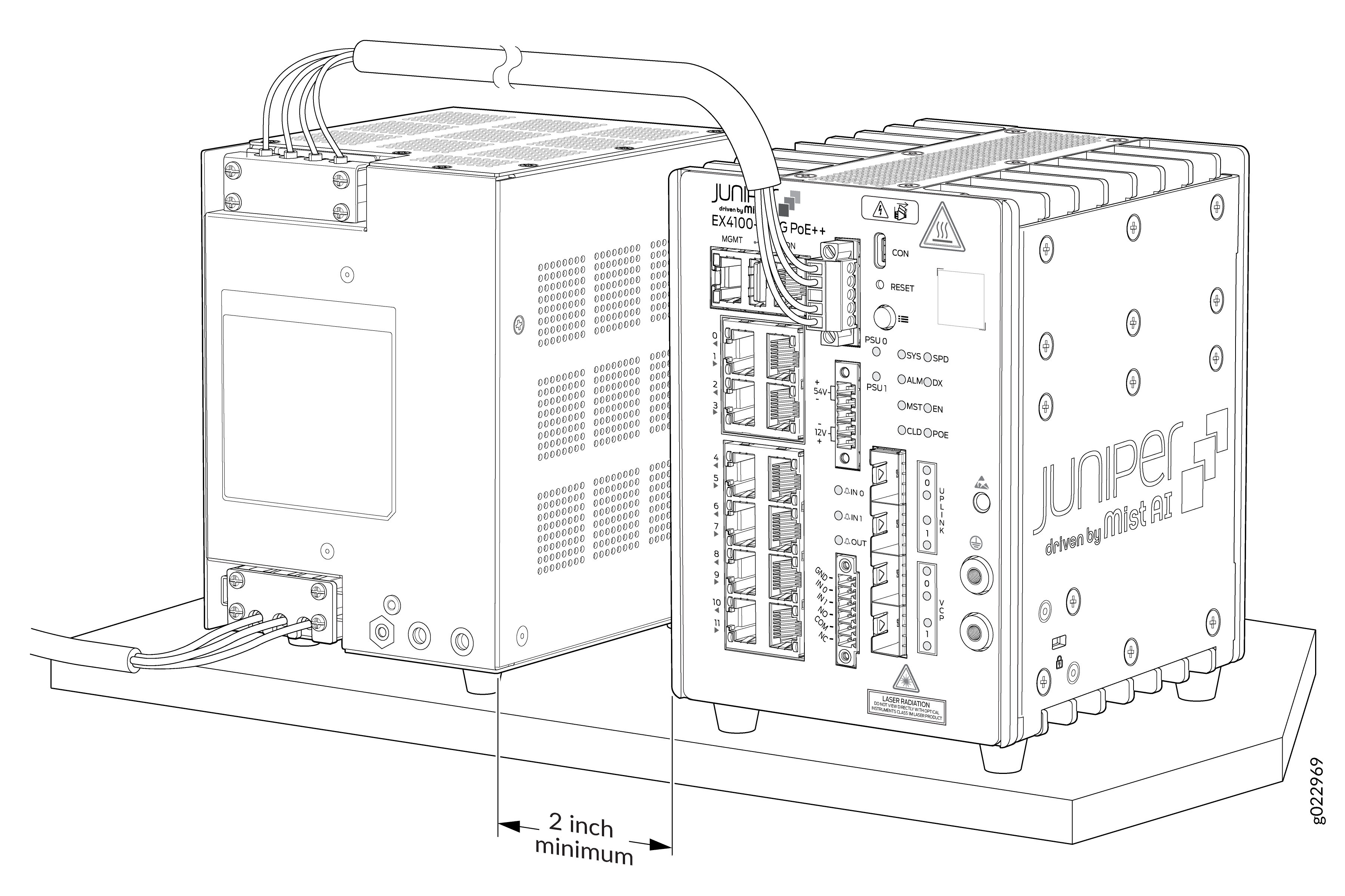
-
Allow a sufficient space of 2 in. all around the switch for cooling. Insufficient space can lead to overheating of the switch chassis.
-
The ferrous wall on which the switch will be mounted shall be flat and the surface shall be without any undulation. The ferrous wall shall be well supported and strong enough to support the switch.
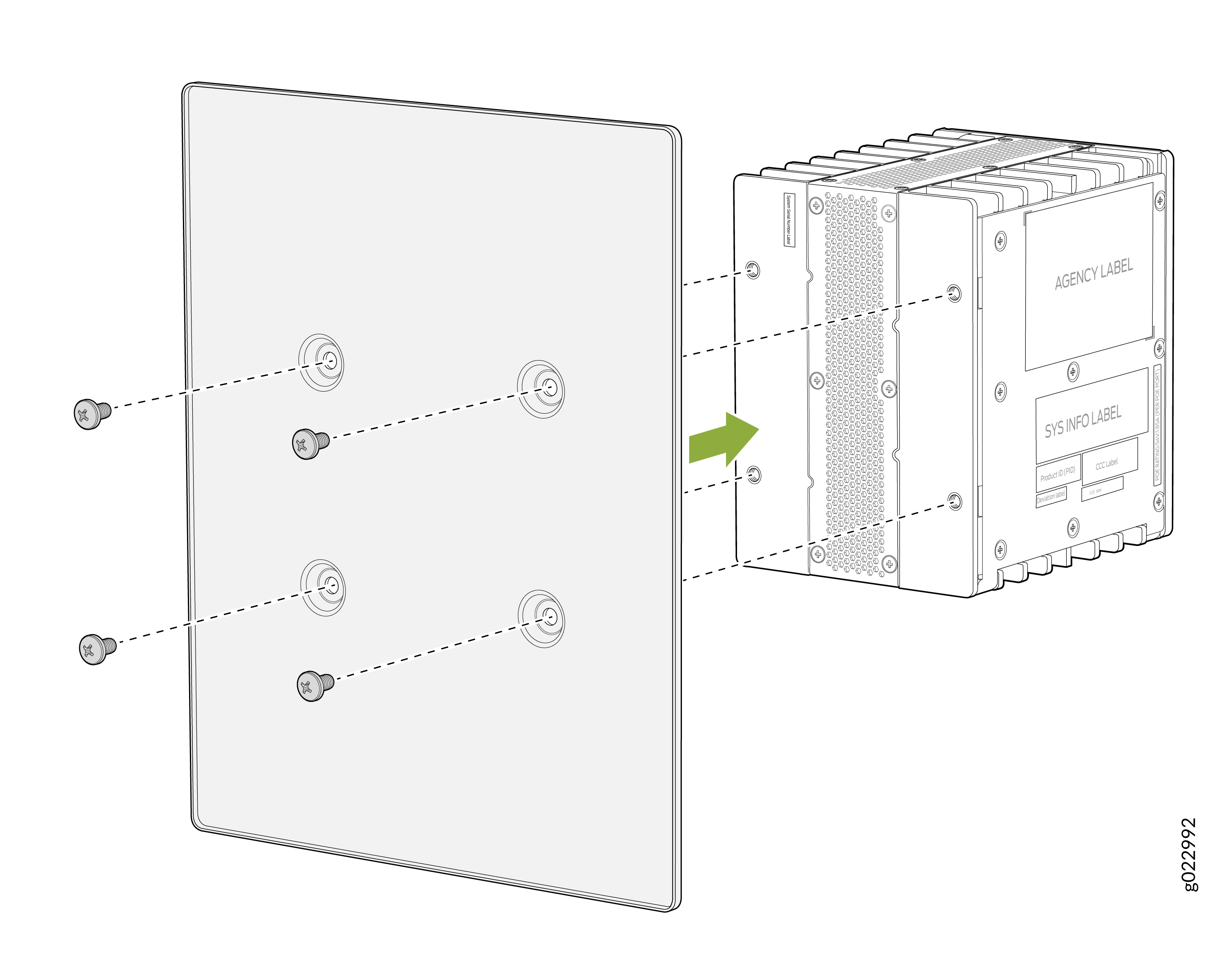
-
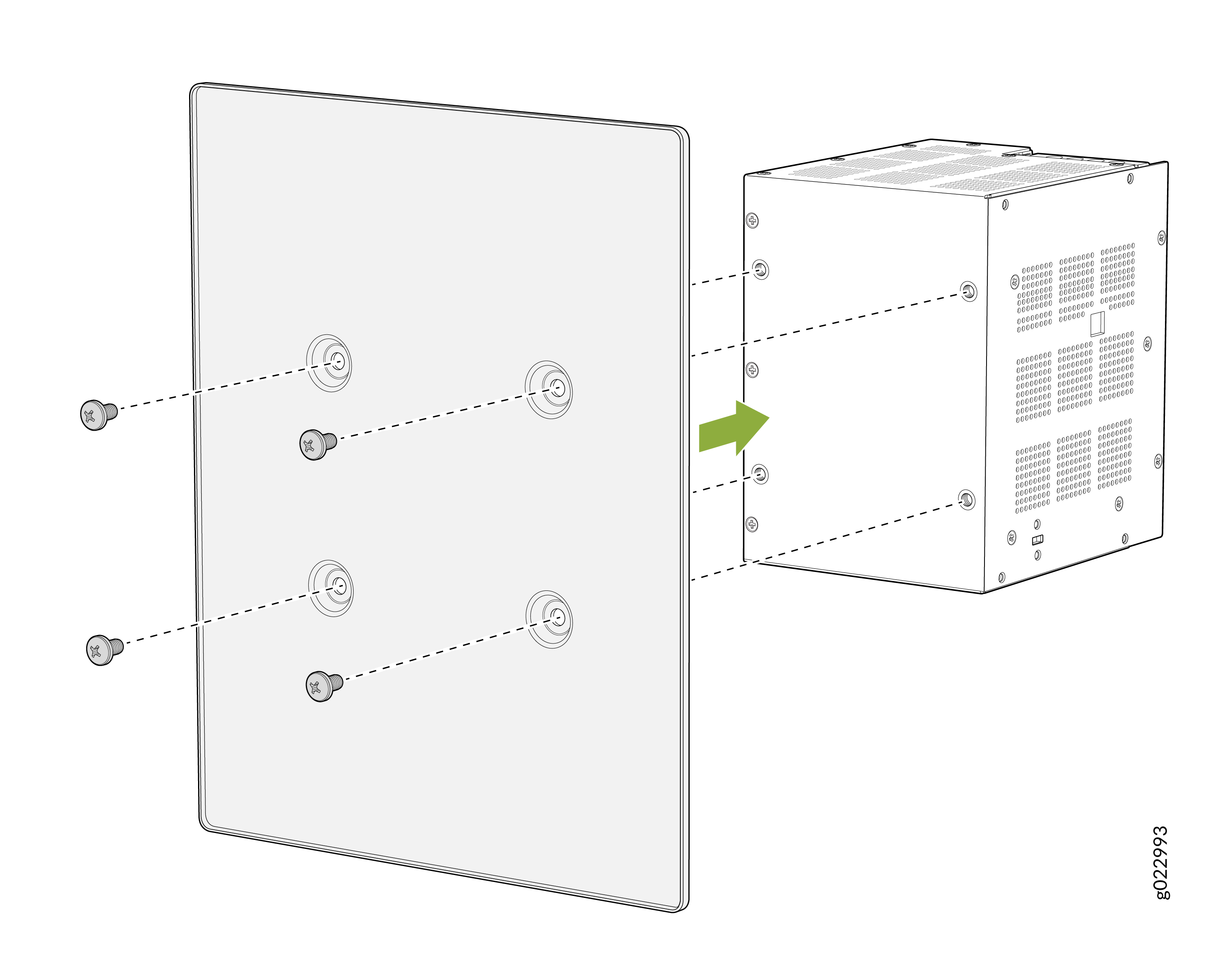
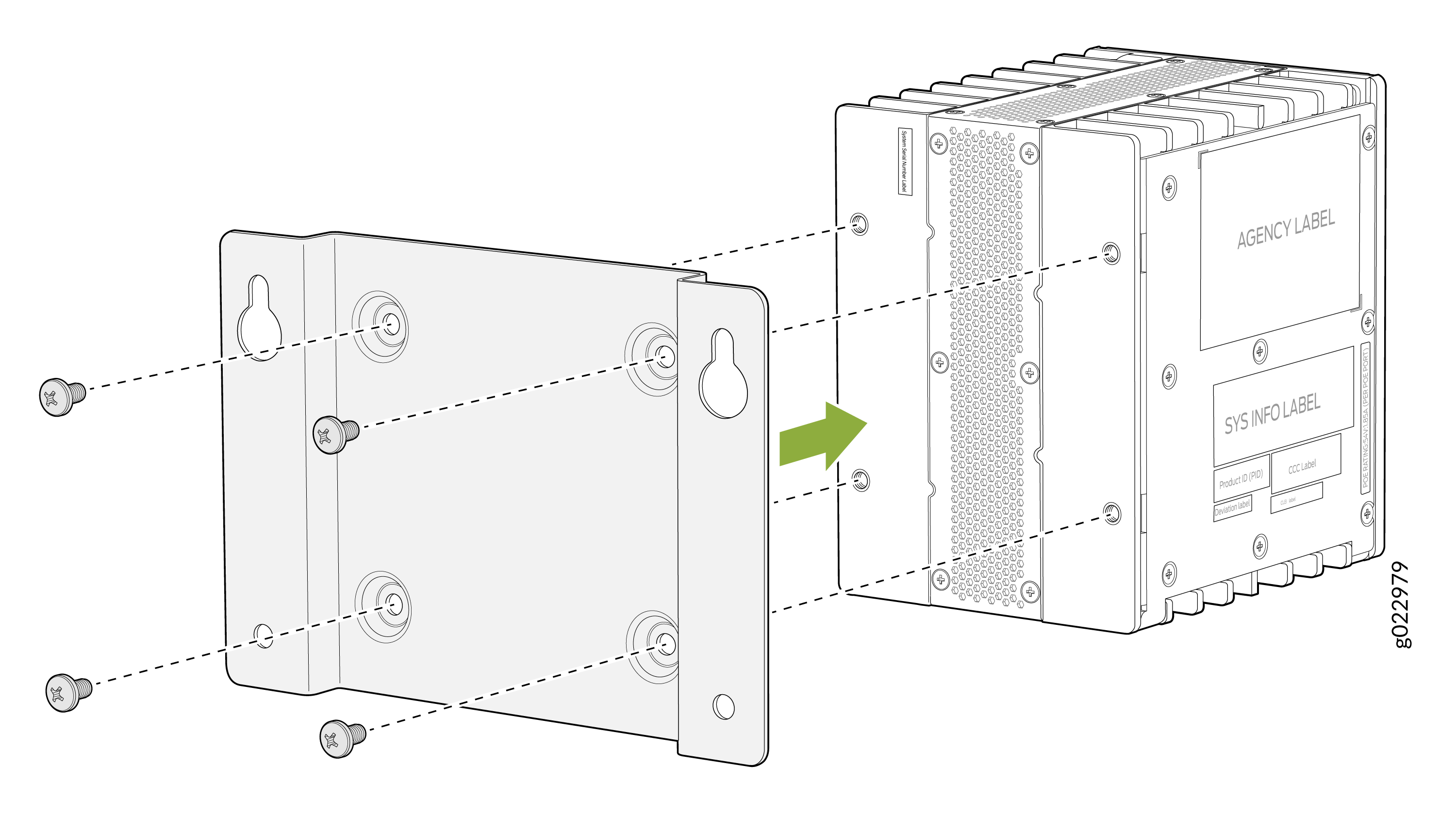
Attach the magnet tray onto the rear of the switch.
Note: Recommended torque for mounting bracket to the switch and PSU:22 +/- 0.5 Lb.inFigure 11: Assemble the magnet tray onto the rear of the switch
-
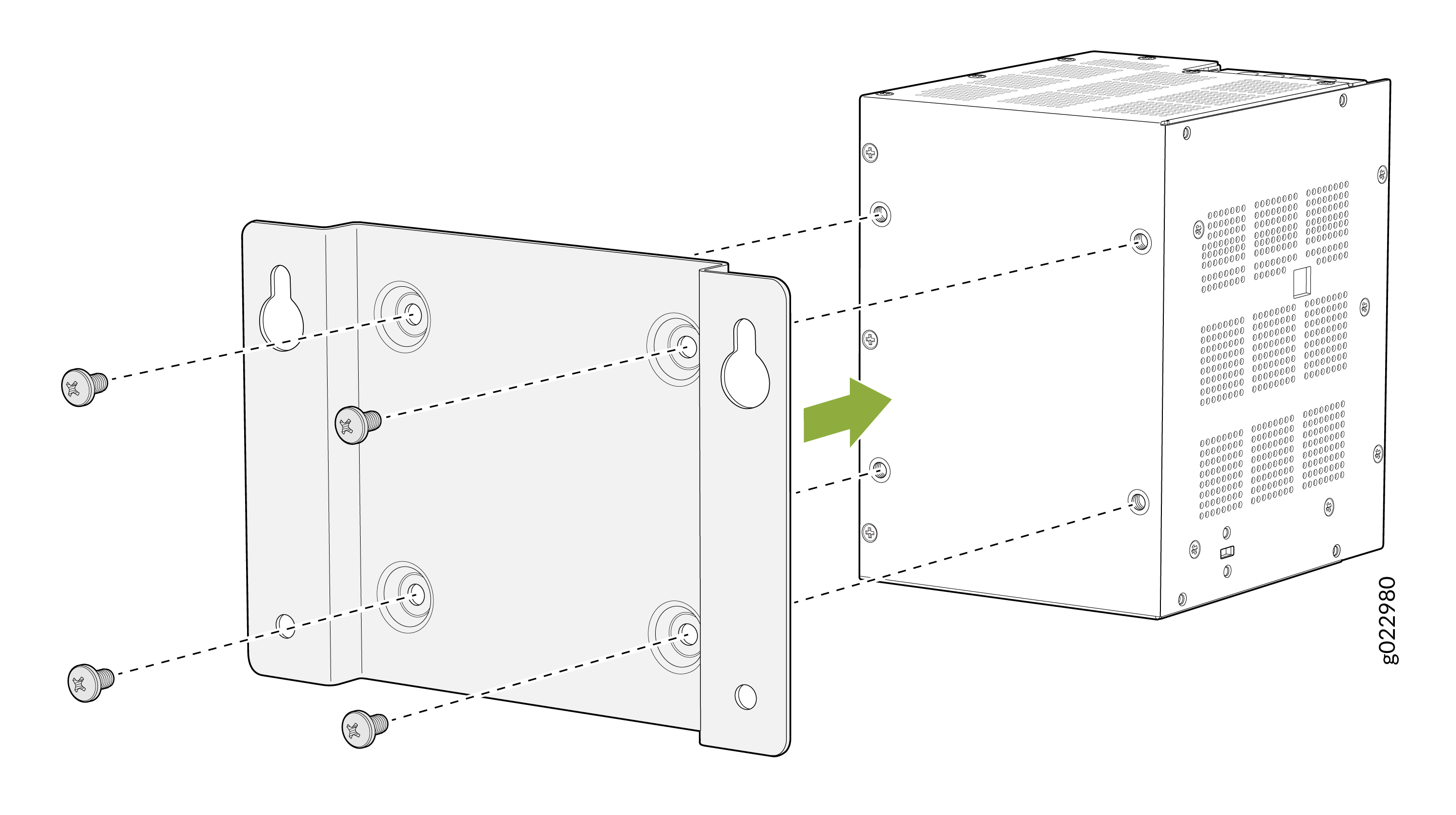
Assemble the magnet tray onto the rear of the PSU.
Figure 12: Assemble the magnet tray onto the rear of the PSU
-
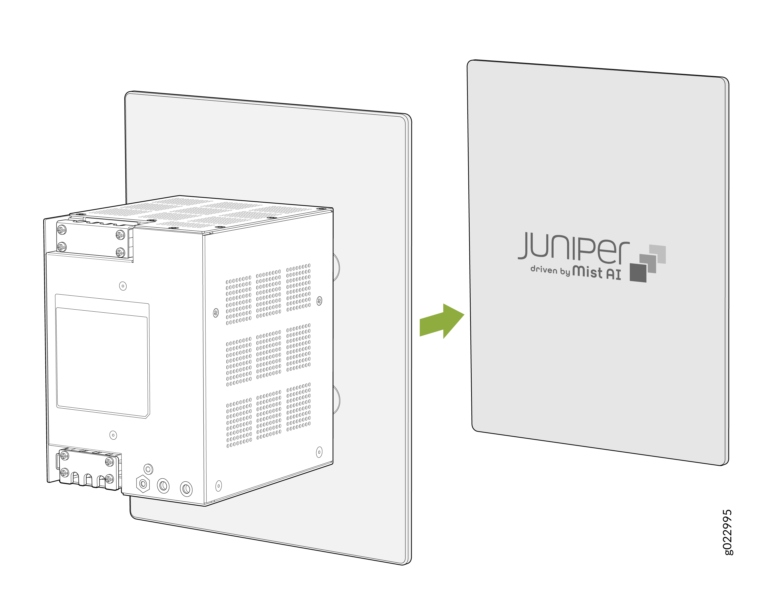
Attach the switch to the magnet pad.
Figure 13: Attach the switch on the magnet pad

-
Attach the PSU to the magnet pad.
Figure 14: Attach the PSU on the magnet pad
-
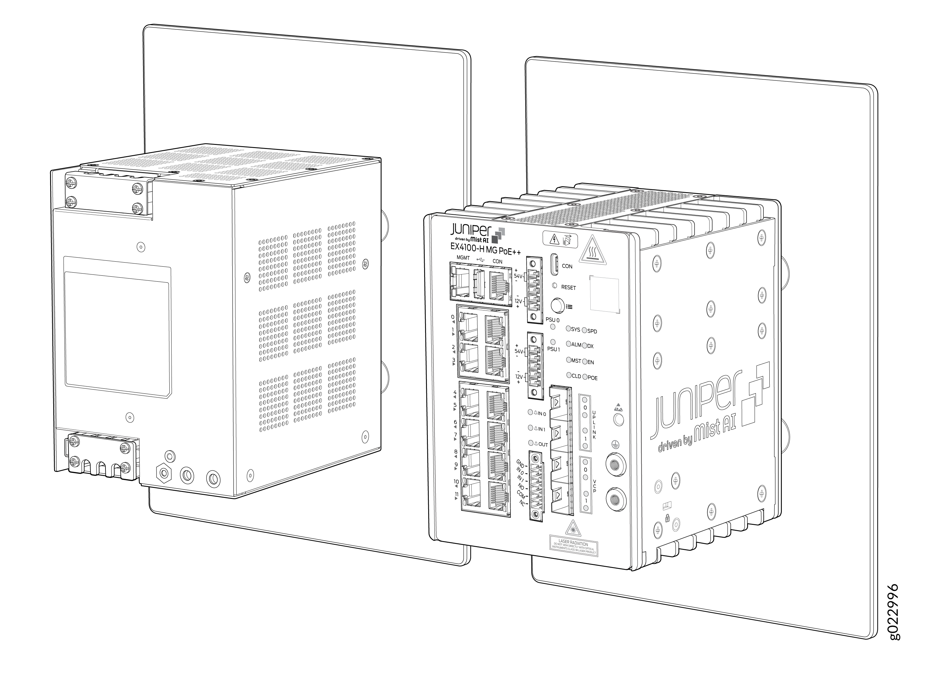
Switch and PSU mounted to the magnetic surface.
Figure 15: The switch and the PSU Mounted to the Magnetic Surface
Mount an EX4100-H-12MP Switch in a Desktop Orientation or on a Flat Surface Within a Cabinet
You can mount the switch and its PSU on a desk or any other level surface within a cabinet. The surface or the area must not be an inclined.
Allow a sufficient space of 2 in. all around the switch for cooling. Insufficient space can lead to overheating of the switch chassis.
Mount an EX4100-H-12MP Switch Using DIN Rail Mount Kit Within a Cabinet
Ensure that you have the following parts and tools available:
-
Two DIN mounting brackets (one for the switch and the other for the PSU)
-
Eight M5 L8 screws
-
The product can be mounted onto a standard 35 mm DIN Rail
-
Allow a sufficient space of 2 in all around the switch for cooling. Insufficient space can lead to overheating of the switch chassis.
-
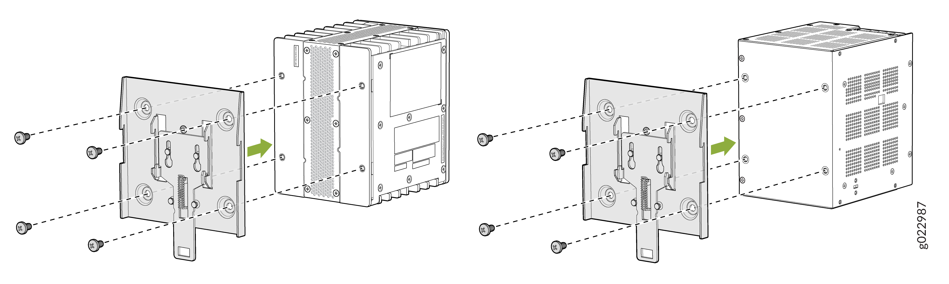
Assemble DIN mounting brackets onto the switch and the PSU.
Note: Recommended torque for mounting bracket to the switch and PSU:22 +/- 0.5 Lb.inFigure 17: Assemble DIN mounting brackets onto the switch and the PSU
-
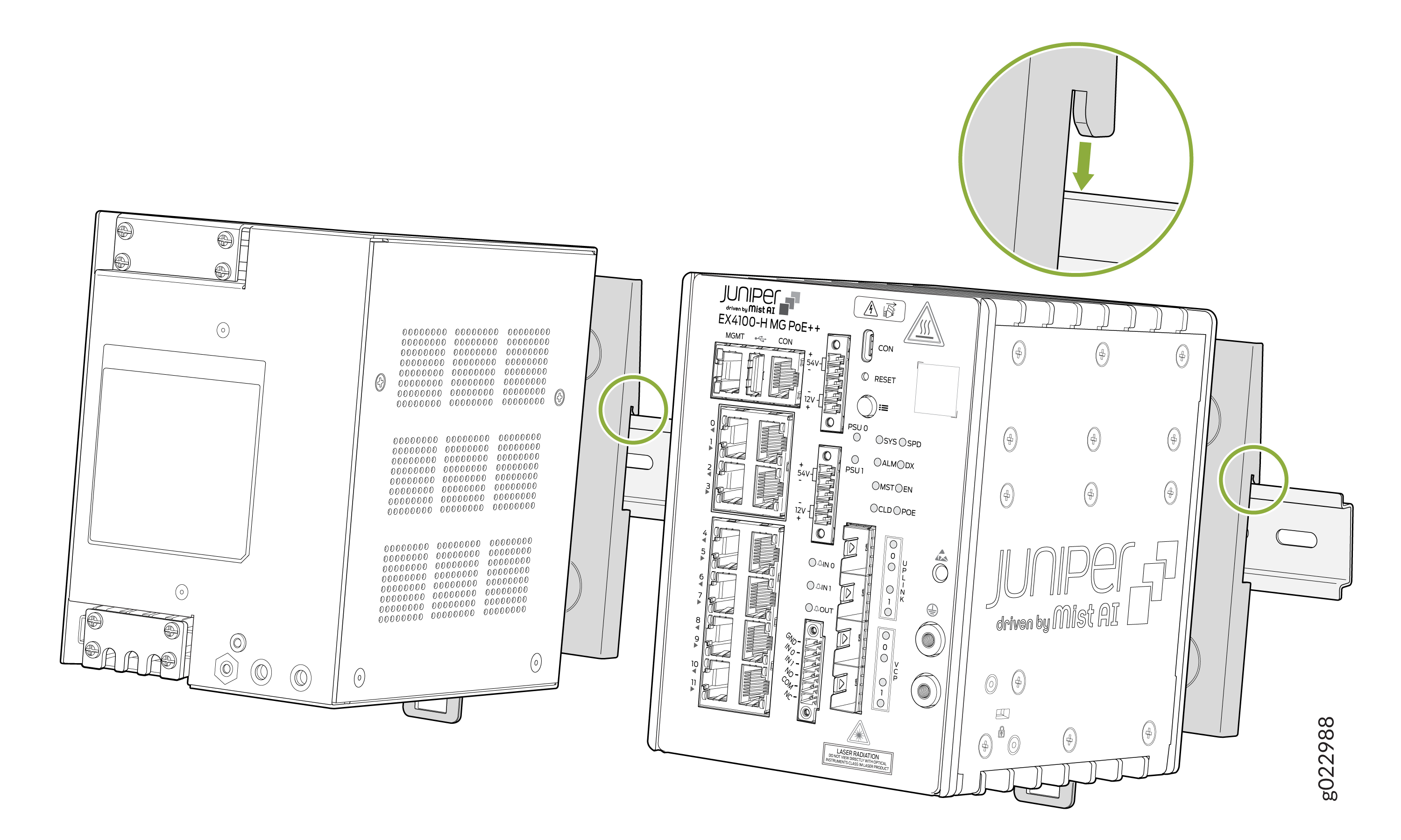
Hook on the switch and the PSU to the DIN channel top side.
Figure 18: Hook on the switch and PSU to the DIN channel top side
-
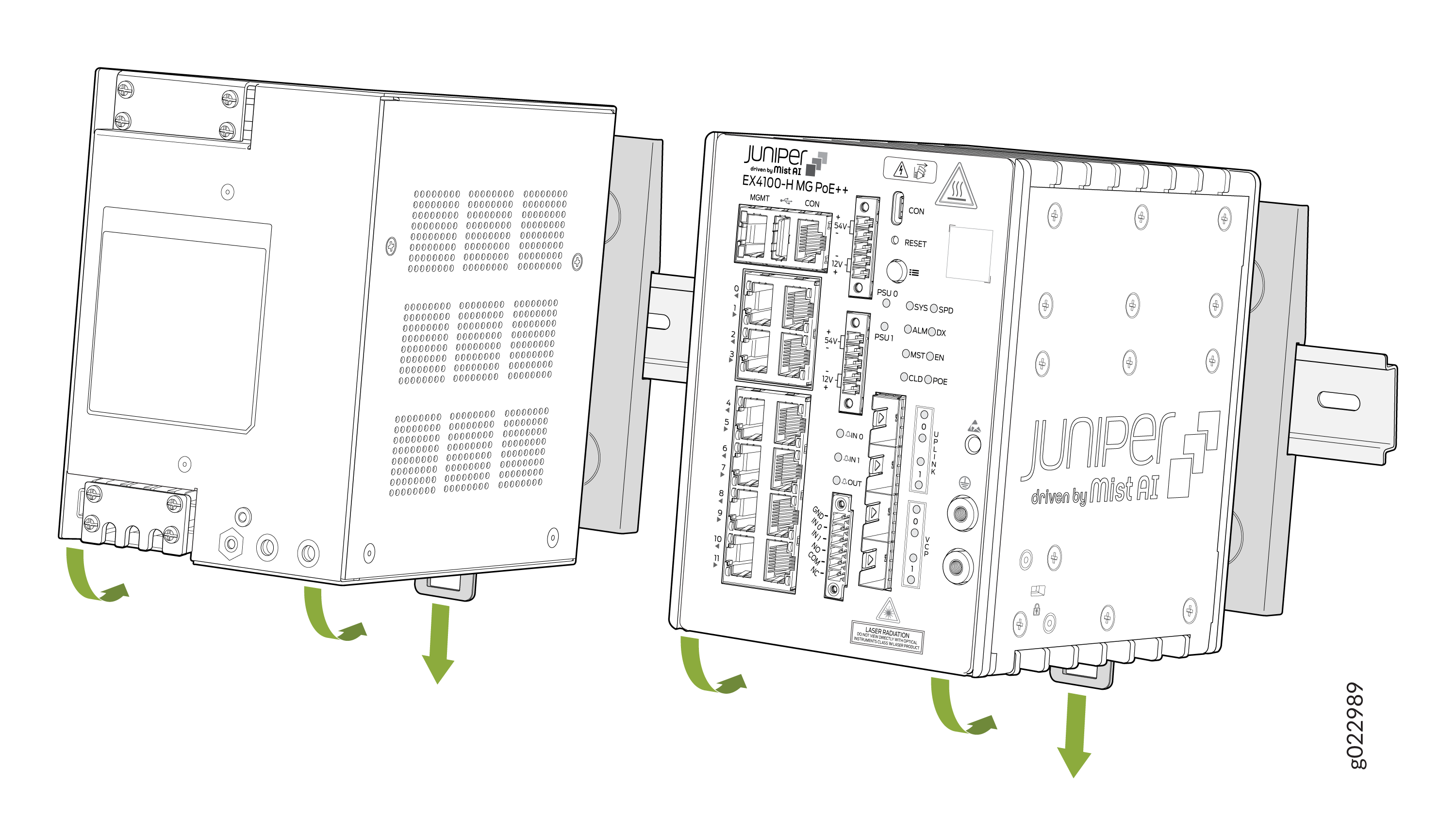
Pull the spring latch to engage the unit to the DIN channel.
Figure 19: Pull the spring latch to engage the unit to the DIN channel
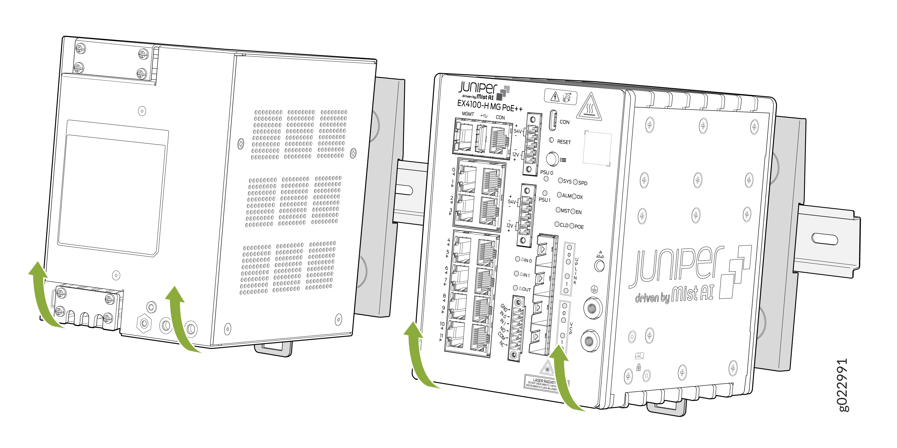
Unmounting an EX4100-H-12MP Switch from a DIN Rail Within a Cabinet
-
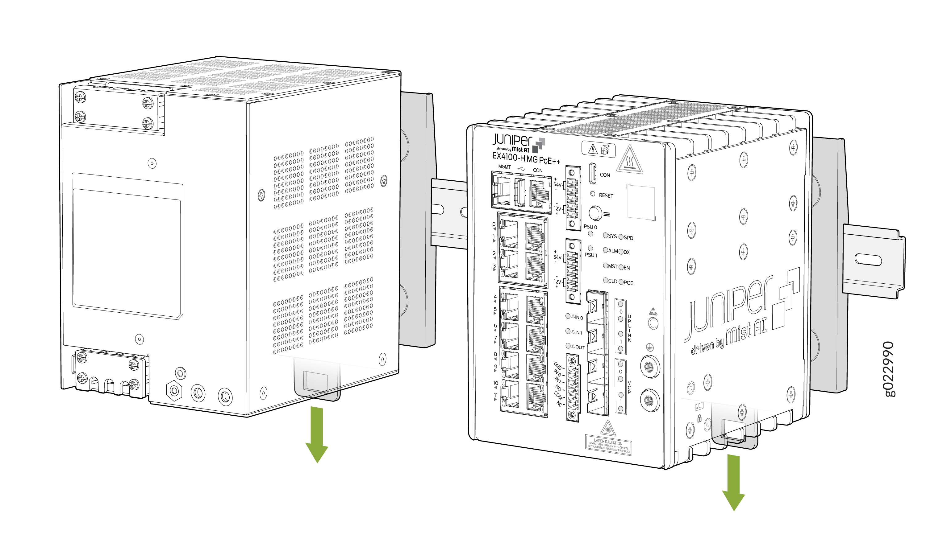
Pull the spring latch to disengage the switch and the PSU.
Figure 20: Pull the spring latch to disengage the switch and PSU
-
Remove the switch and the PSU from the DIN rail.
Figure 21: Remove the switch and PSU from the DIN rail
Mount an EX4100-H-12MP Switch on a Wall Within a Cabinet
Before mounting the switch on a wall:
-
Verify that the site meets the requirements described in Site Preparation Checklist for EX4100-H Switches.
-
Read General Safety Guidelines and Warnings with particular attention to Chassis and Component Lifting Guidelines.
. Ensure that you have the following parts and tools available:
-
Two wall-mounting brackets (provided in the wall-mounting kit)
-
Eight wall-mounting bracket screws (provided in the wall-mounting kit)
-
Eight mounting screws to attach the switch and the external PSU using M5 x 8 mm (provided in the wall-mounting kit)
-
Hollow wall anchors (provided in the wall-mounting kit)
-
A Number 2 Phillips (+) screwdriver (not provided)
You can mount an EX4100-H-12MP switch on a wall by using the separately orderable wall-mounting kit.
To mount the switch and the external PSU on a wall within a cabinet:
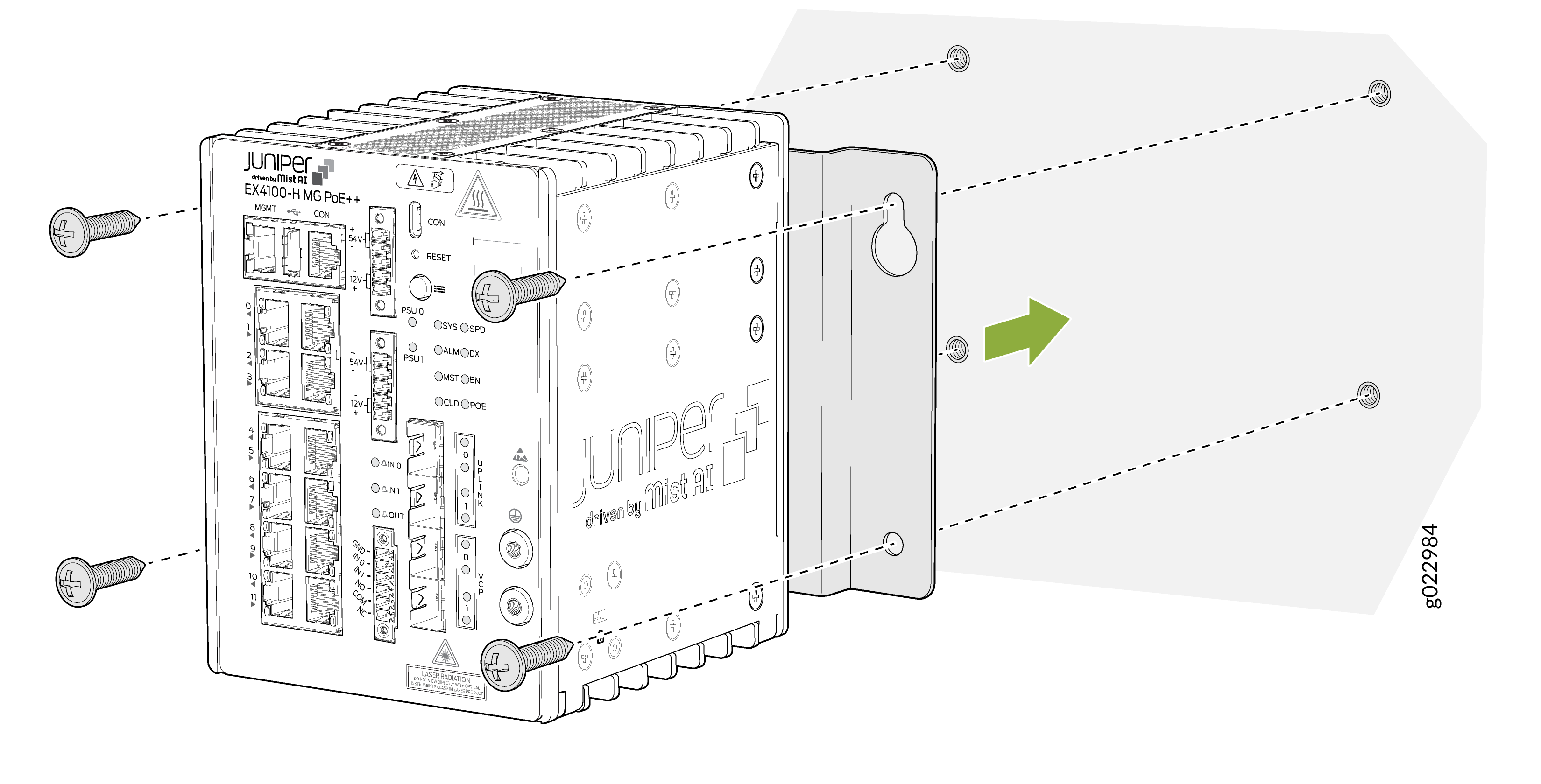
-
Attach the wall-mounting bracket to the switch.
Note: Recommended torque for mounting bracket to the switch and PSU:22 +/- 0.5 Lb.inFigure 22: Attach wall-mounting bracket to the switch
-
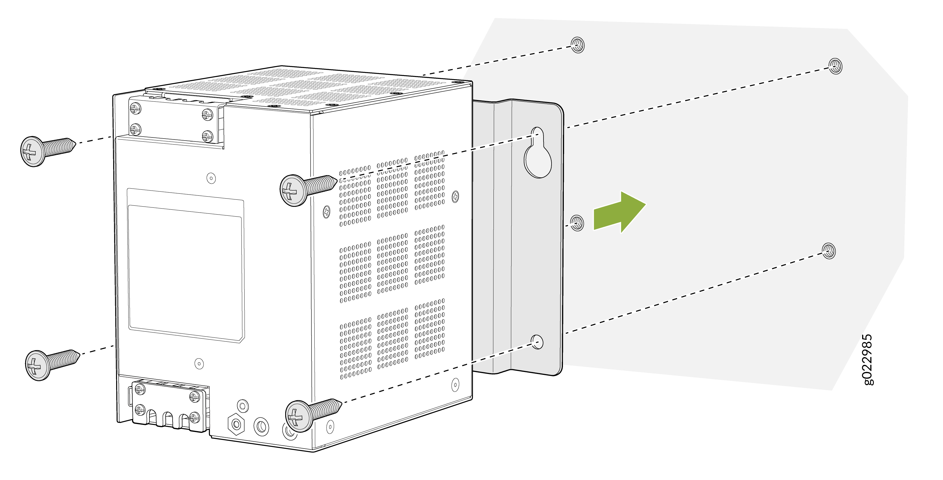
Attach wall-mounting bracket to the PSU.
Figure 23: Attach wall-mounting bracket to the PSU
-
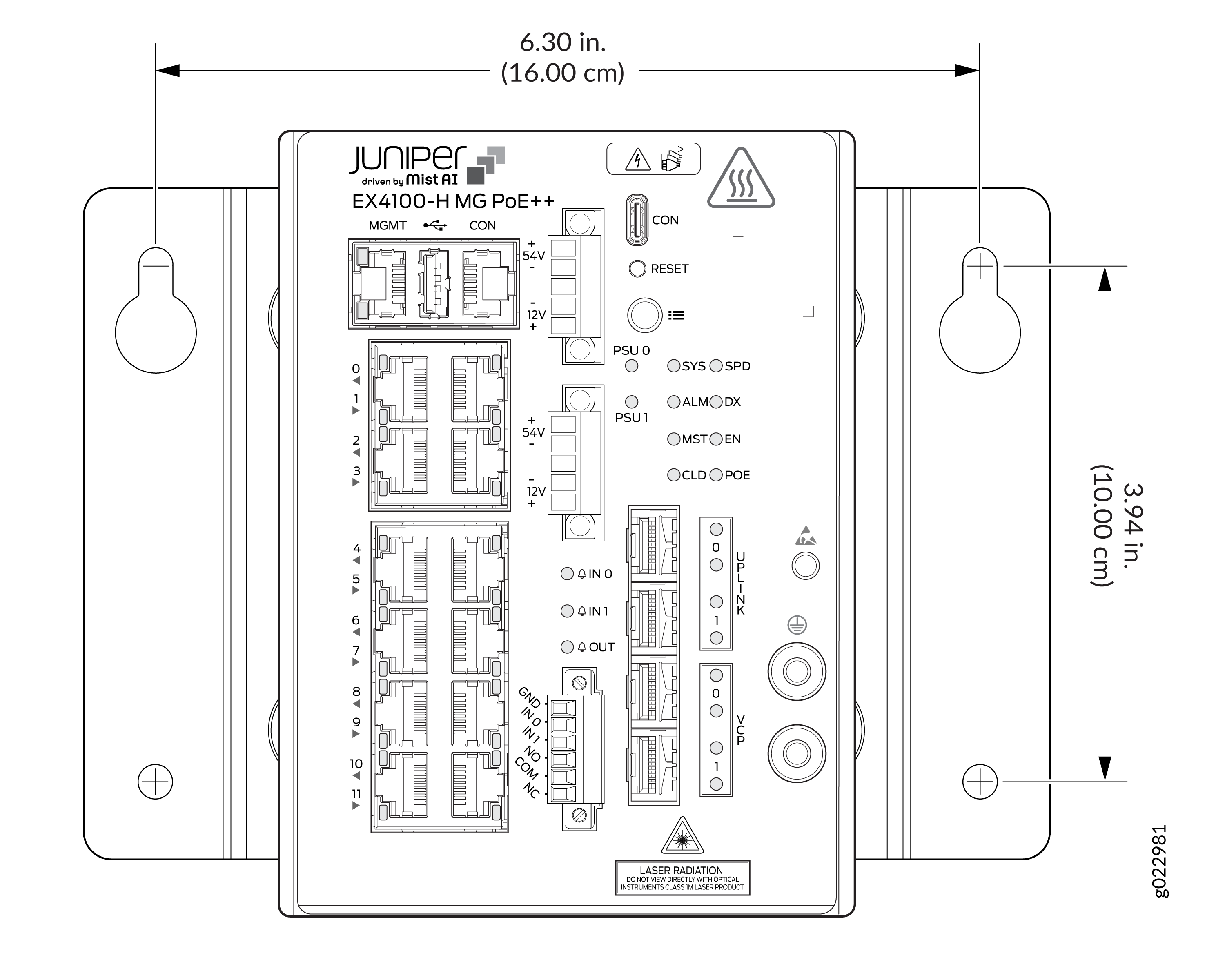
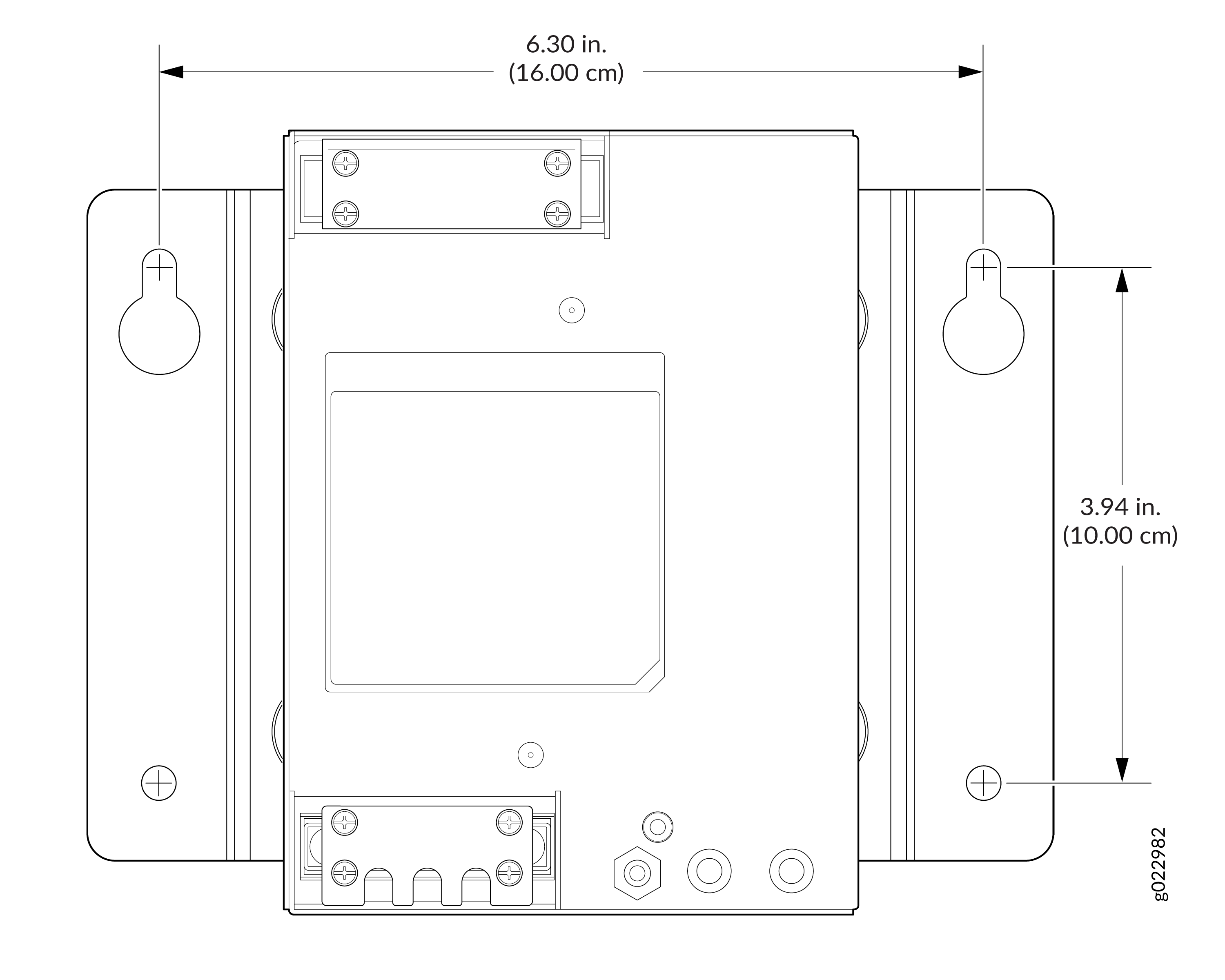
Drill holes as per the measurements in the following figure to install the
mounting screws for the wall-mounting brackets of the switch. If the mounting
screws are inserted in a wall board with no stud behind it, you must use dry wall
anchors rated to support 75 lb (34 kg). Insert the screws into wall studs wherever
possible to provide added support for the switch chassis.Tighten the screws only
partway in, leaving about 1/4 in. (6 mm) distance between the head of the screw
and the wall.
Figure 24: Measurements for installing mounting screws for the mounting brackets of the switch
-
Drill holes as per the measurements in the following figure to install the
mounting screws for the wall-mounting brackets of the PSU. If the mounting
screws are inserted in a wall board with no stud behind it, you must use dry
wall anchors rated to support 75 lb (34 kg). Insert the screws into wall
studs wherever possible to provide added support for the PSU chassis.Tighten
the screws only partway in, leaving about 1/4 in. (6 mm) distance between
the head of the screw and the wall.
Figure 25: Measurements for installing mounting screws for the mounting brackets of the PSU
-
Secure the switch to the wall using screws. Tighten all mounting
screws.
Figure 26: Secure the switch to the wall using screws
-
Secure the PSU to the wall using screws. Tighten all mounting screws.
Figure 27: Secure the PSU to the wall using screws
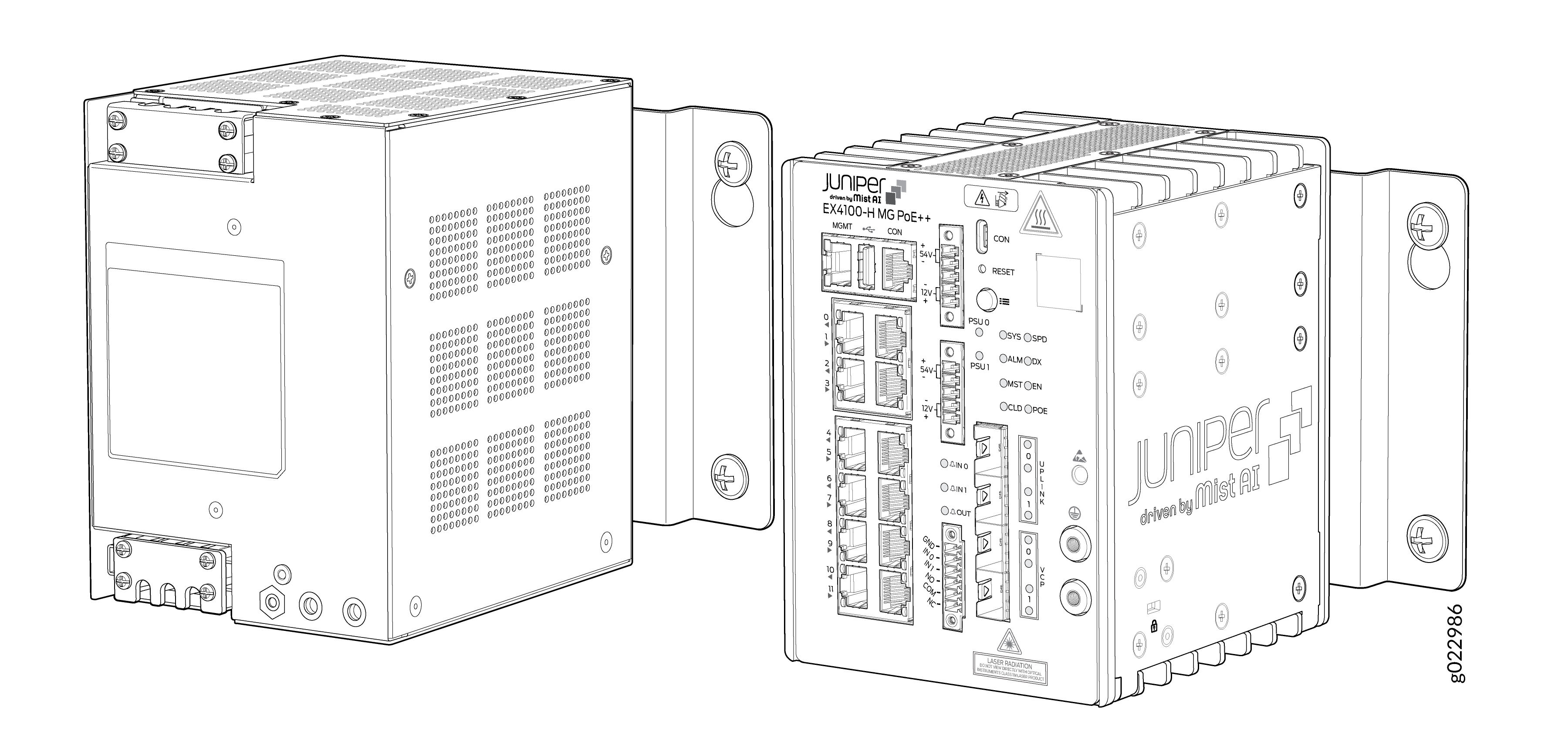
-
Switch and PSU installed on the wall within a cabinet.
Figure 28: Switch and PSU installed on the wall
Mount an EX4100-H-24MP or EX4100-H-24F Switch in a Rack Within a Cabinet
Two-post rack mounting is the default mounting option for the EX4100-H-24MP and EX4100-H-24F switch.
Maintain a clearance of 1 RU on top of the switch and 1 RU on bottom of the switch.
-
Verify that the site meets the requirements described in Environmental Requirements and Specifications
-
Place the rack in its permanent location, allowing adequate clearance for airflow and maintenance, and secure it to the building structure.
-
Read General Safety Guidelines and Warnings, with particular attention to Chassis and Component Lifting Guidelines.
Ensure that you have the following parts and tools available:
-
Phillips (+) screwdriver, number 2 (not provided).
-
Screws to secure the switch chassis to the rack (not provided).
-
2-post rack mounting kit - EX4100-H-2P-RMK (provided).
-
Four M4 x 6 Screws (provided)
You can mount the EX4100-H-24MP and EX4100-H-24F switches on two posts of a 19-in. rack or cabinet by using the front mounting brackets provided with the switch. (The remainder of this topic uses rack to mean rack or cabinet.)
One person must be available to lift the switch while another secures the switch to the rack.
If you are mounting multiple units on a rack, mount the heaviest unit at the bottom of the rack and mount the other units from the bottom of the rack to the top in decreasing order of the weight of the units.
-
Attach the 2-post mounting brackets to the switch chassis by initially attaching
the side mounting brackets to the switch chassis by aligning the keyholes on the
mounting brackets over the shoulder screws on the switch chassis. Each keyhole on
the mounting bracket has a neck and a head; the neck is narrower. Place the
keyholes on the mounting brackets over the shoulder screws on the switch chassis
and slide the mounting brackets towards the rear of the switch chassis such that
the shoulder screws on the switch chassis are positioned into the heads of the
keyholes on the mounting bracket.
Figure 29: Attach the 2-post mounting brackets to the chassis
-
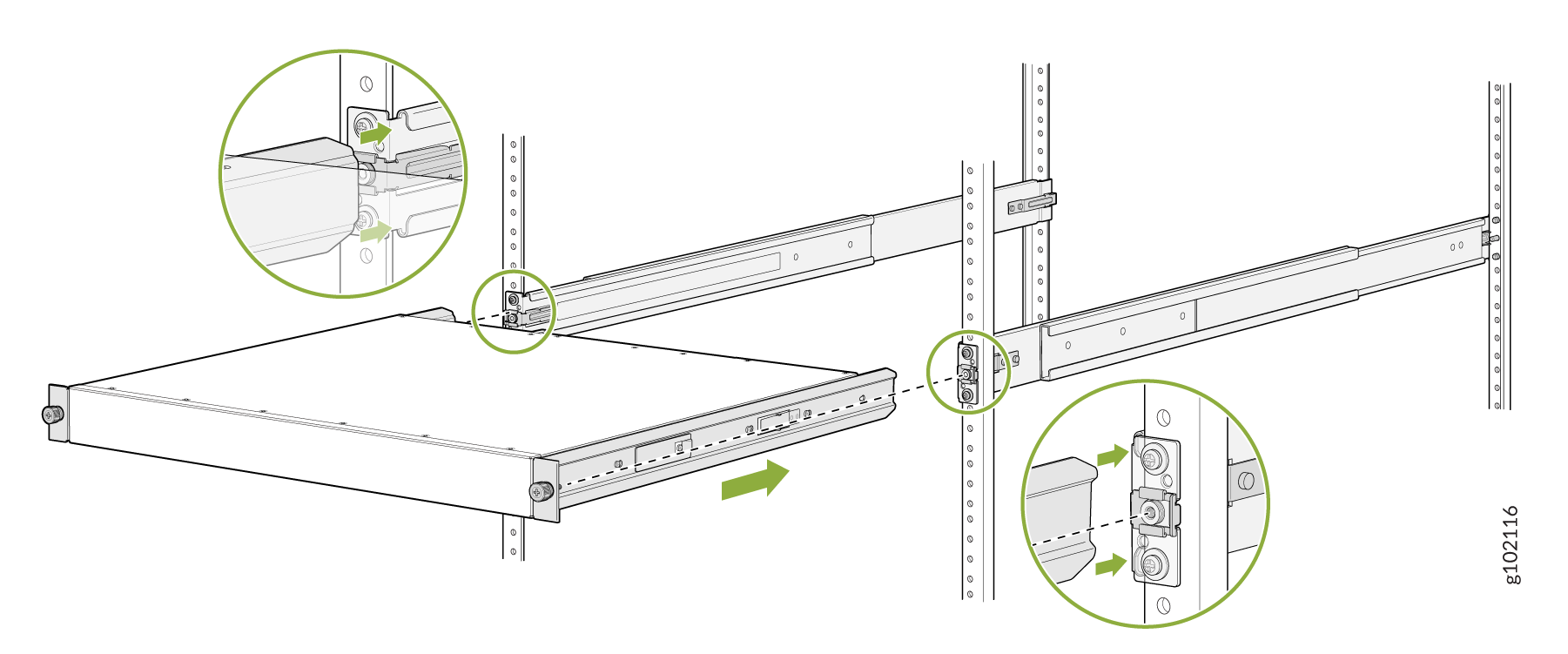
To attach the switch to the rack, lift the switch, and position it in the rack,
aligning the holes of the mounting brackets with the threaded holes in the posts
of the rack. Align the holes in each mounting bracket with a hole in each rack
rail, ensuring that the switch chassis is level. Have a second person secure the
switch to the rack. Use eight screws appropriate for your rack to attach the
mounting brackets to the rack and tighten the screws.
Figure 30: Attach the mounting brackets to the rack
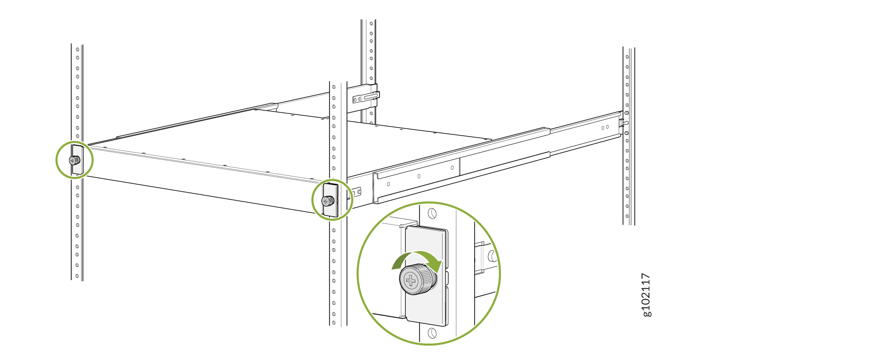
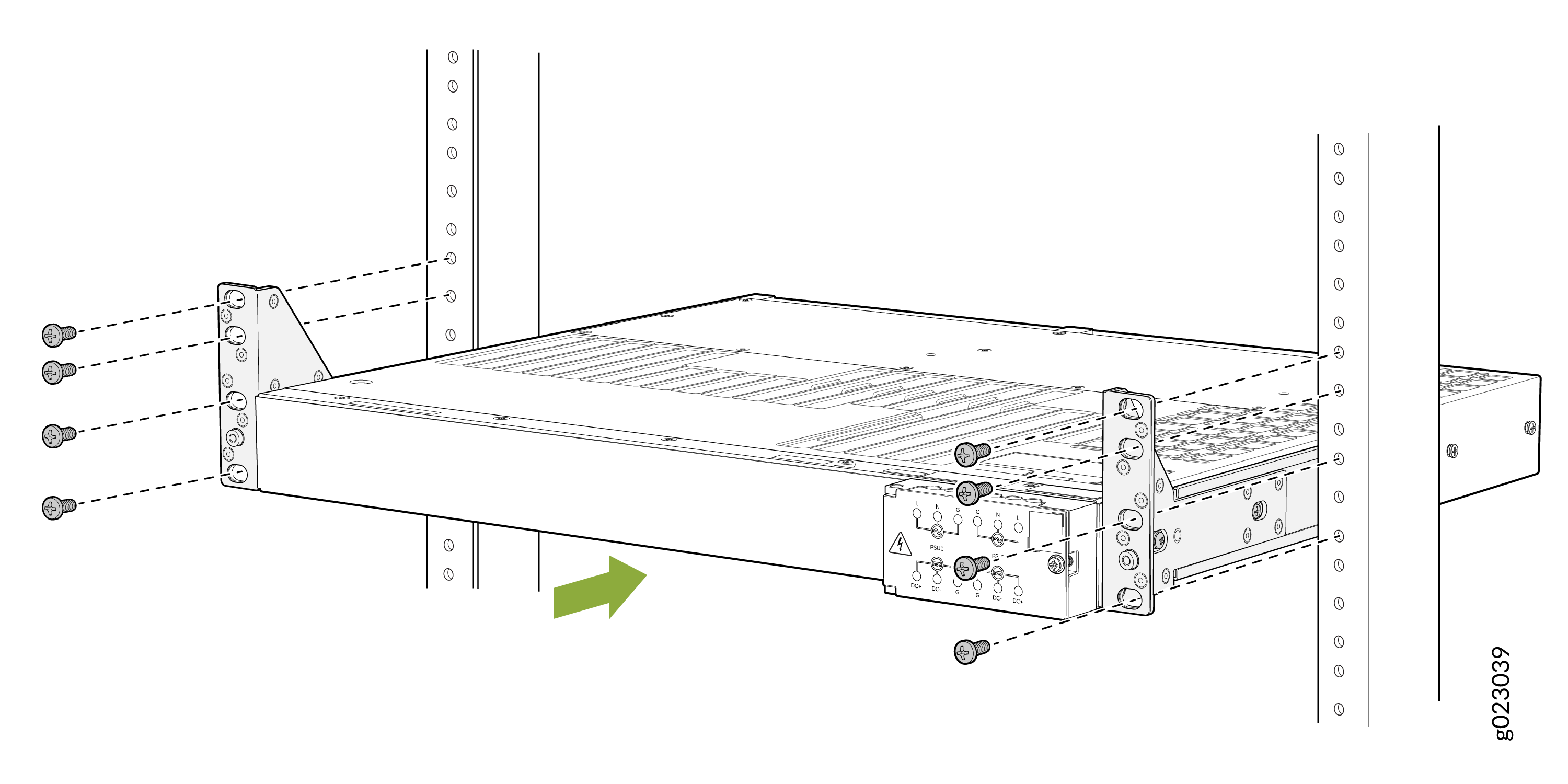 Figure 31: Switch installed in the rack
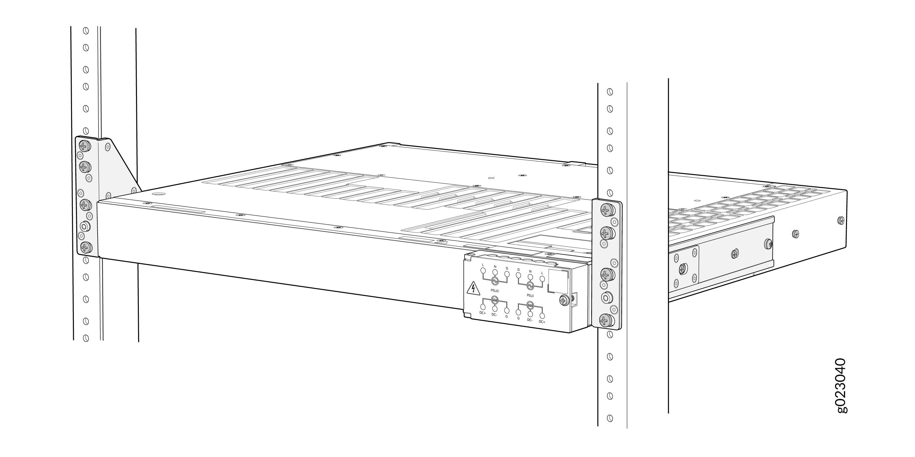
Mount an EX4100-H-24MP or EX4100-H-24F Switch By Using EX4100-H-4P-RMK (Screw Mount) on Four Posts in a Rack or Cabinet
-
Verify that the site meets the requirements described in Environmental Requirements and Specifications
-
Place the rack in its permanent location, allowing adequate clearance for airflow and maintenance, and secure it to the building structure.
-
Read General Safety Guidelines and Warnings, with particular attention to Chassis and Component Lifting Guidelines.
Ensure that you have the following parts and tools available:
-
One pair of front mounting brackets for mounting the switch flush with the front posts of a rack - (provided with four-post rack mount kit)
-
One pair of rear mounting brackets (provided with four-post rack mount kit)
-
Four M4 x 6 screws (provided with the four-post rack mount kit)
-
Phillips (+) screwdriver, number 2 (not provided)
-
Screws to secure the switch chassis and the rear-mounting blades to the rack (not provided)
You can mount an EX4100-H-24MP or EX4100-H-24F switch on four posts of a 19-in. rack or cabinet by using the separately orderable four-post rack-mounting kit (EX4100-H-4P-RMK). (The remainder of this topic uses rack to mean rack or cabinet.)
One person must be available to lift the switch while another secures the switch to the rack.
Maintain a clearance of 1 RU on top of the switch and 1 RU on bottom of the switch.
If you are mounting multiple units on a rack, mount the heaviest unit at the bottom of the rack and mount the other units from the bottom of the rack to the top in decreasing order of the weight of the units.
To mount the switch on four posts in a rack:
-
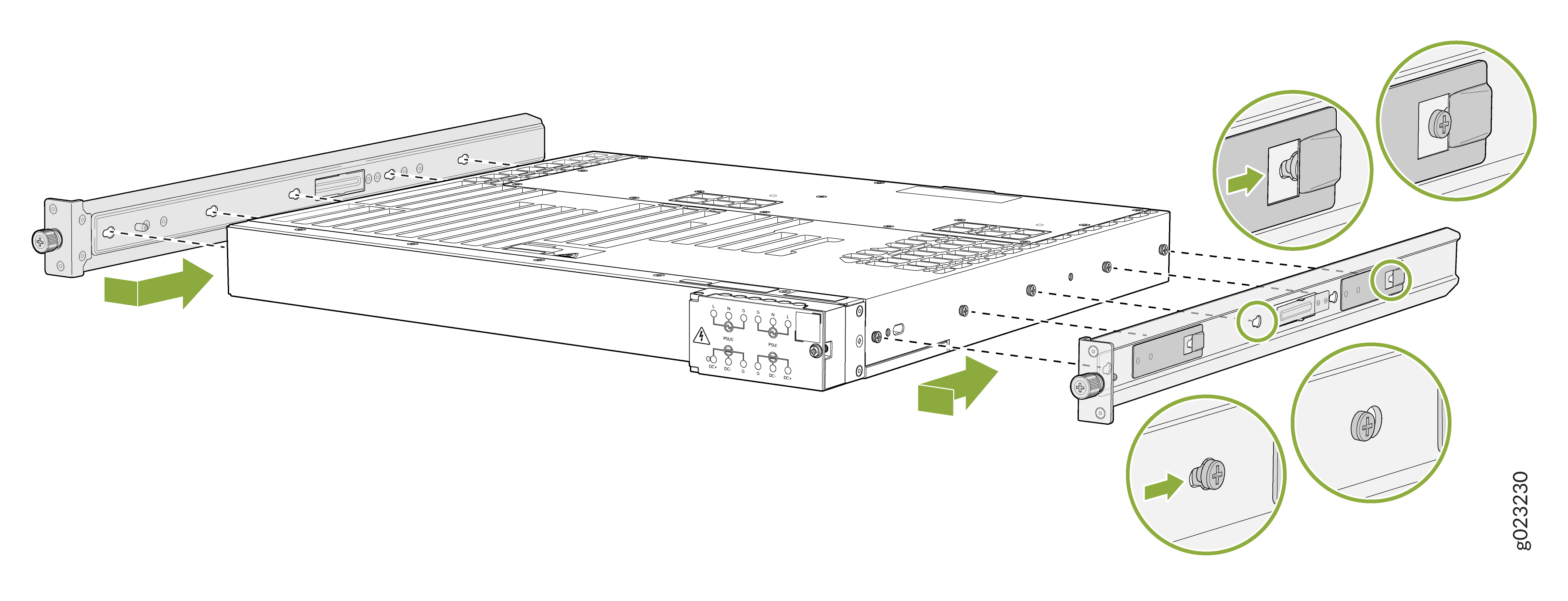
Each keyhole on the mounting bracket has a neck and a head; the neck is
narrower. Place the keyholes on the mounting brackets over the shoulder
screws on the chassis and slide the mounting brackets towards the rear of
the chassis such that the shoulder screws on the chassis are positioned into
the heads of the keyholes on the mounting bracket.
- Insert the M4 x 6mm Phillips screws to attach the mounting bracket into the aligned holes on the chassis and tighten the screws with a recommended torque of 10 +/- 0.5 Lb.in.
Figure 32: Attach the mounting brackets to the switch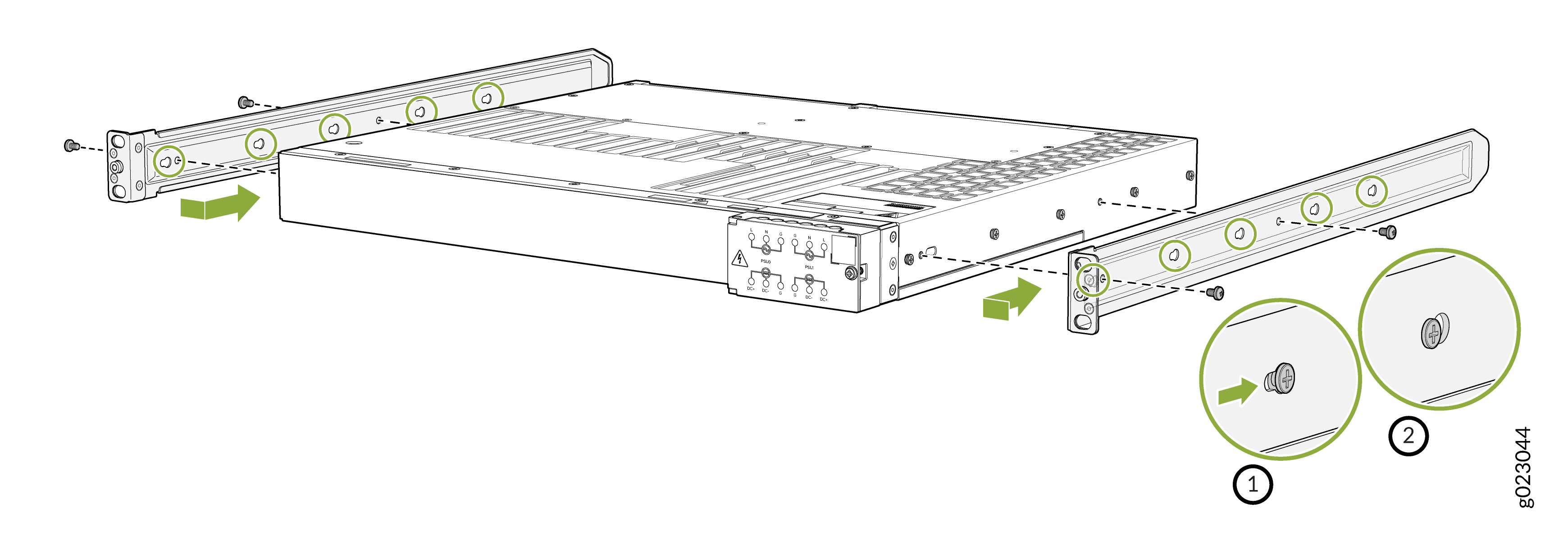
-
To attach the switch to the rack, lift the switch, and position it in the rack,
aligning the holes of the mounting brackets with the threaded holes in the posts
of the rack. Align the holes in each mounting bracket with a hole in each rack
rail, making sure that the switch chassis is level.
- Secure the switch to the front posts of the rack.
Figure 33: Secure the front-mounting brackets and switch chassis to the rack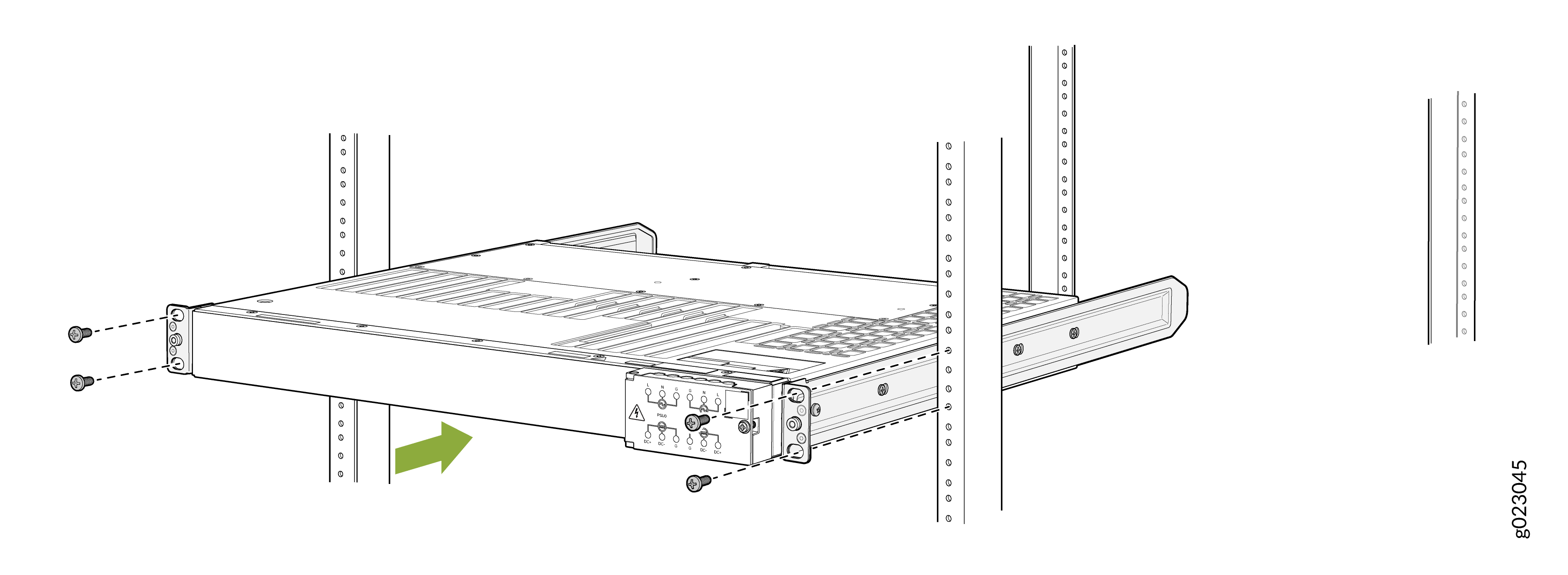
-
Slide the rear mounting bracket blades into the side rails of the front
mounting brackets attached to the switch chassis.
- Secure the switch to the rear post of the rack by using the rear mounting brackets and tighten the screws
Figure 34: Attach rear mounting bracket blades to the switch and attach rear mounting brackets to the switch chassis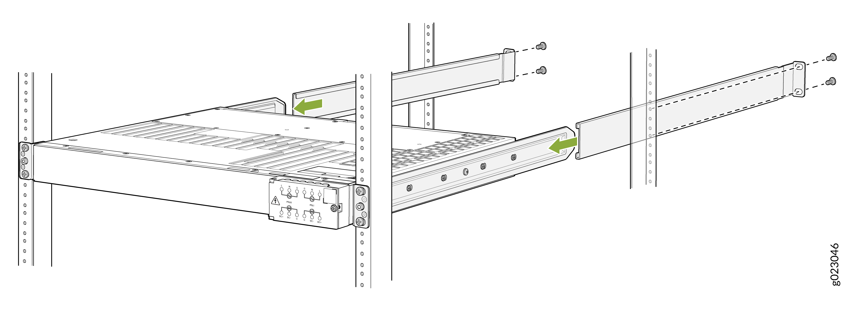
Mount an EX4100-H 24MP or EX4100-H 24F Switch in a Rack or Cabinet by Using the EX4100-H-4P-TL-RMK Tool less Rack Mount Kit
You can mount the EX4100-H 24MP or EX4100-H 24F switch on a square hole or threaded hole four-post 19-in. racks using the tool less EX4100-H-4P-TL-RMK rack mount kit.
A four-post installation evenly supports the switch by all four corners.
- Mount your Switch by Using the EX4100-H-4P-TL-RMK Tool less Rack Mount Kit on a Square Hole 4-Post Rack
- Mount your Switch by Using the EX4100-H-4P-TL-RMK Tool less Rack Mount Kit on a Threaded-Hole 4-Post Rack
Mount your Switch by Using the EX4100-H-4P-TL-RMK Tool less Rack Mount Kit on a Square Hole 4-Post Rack
Ensure that you have the following tools and parts available:
-
An ESD grounding strap—not provided.
-
A pair of side mounting brackets that attach to the switch chassis—provided with the rack mount kit.
-
A pair of front and rear mounting rails that attach to the rack posts—provided with the rack mount kit.
Maintain a clearance of 1 RU on top of the switch and 1 RU on bottom of the switch.
To mount the switch on a four-post rack:
-
To attach the side mounting brackets to the switch chassis, align the
keyholes on the mounting brackets over the shoulder screws on the switch
chassis. Slide the mounting brackets toward the rear of the switch
chassis.
Figure 35: Attach the Side Mounting Brackets
-
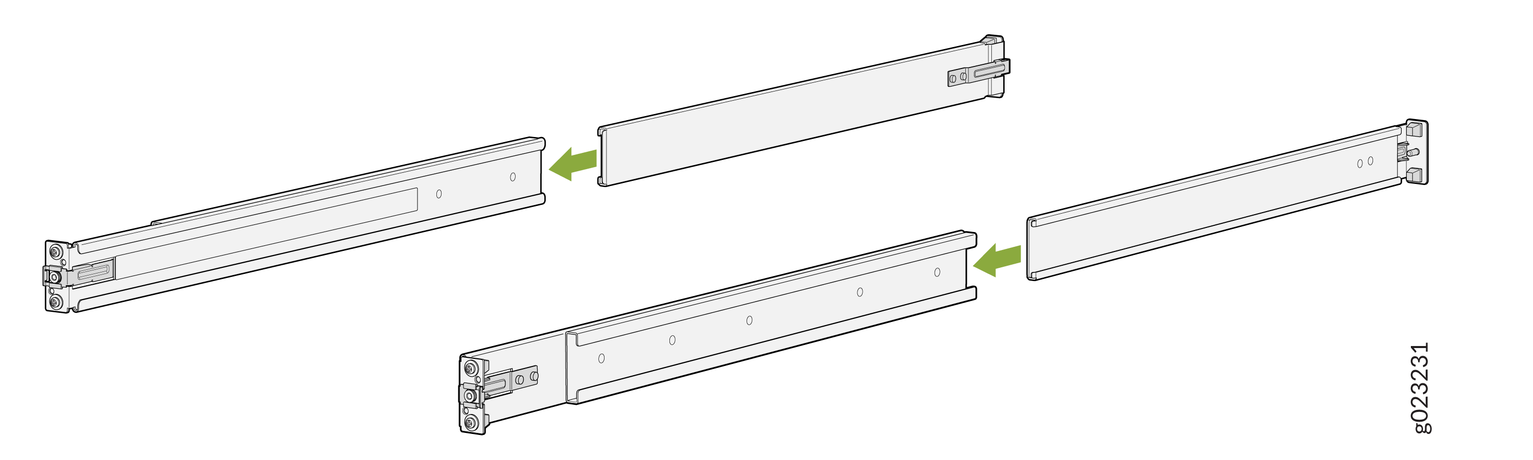
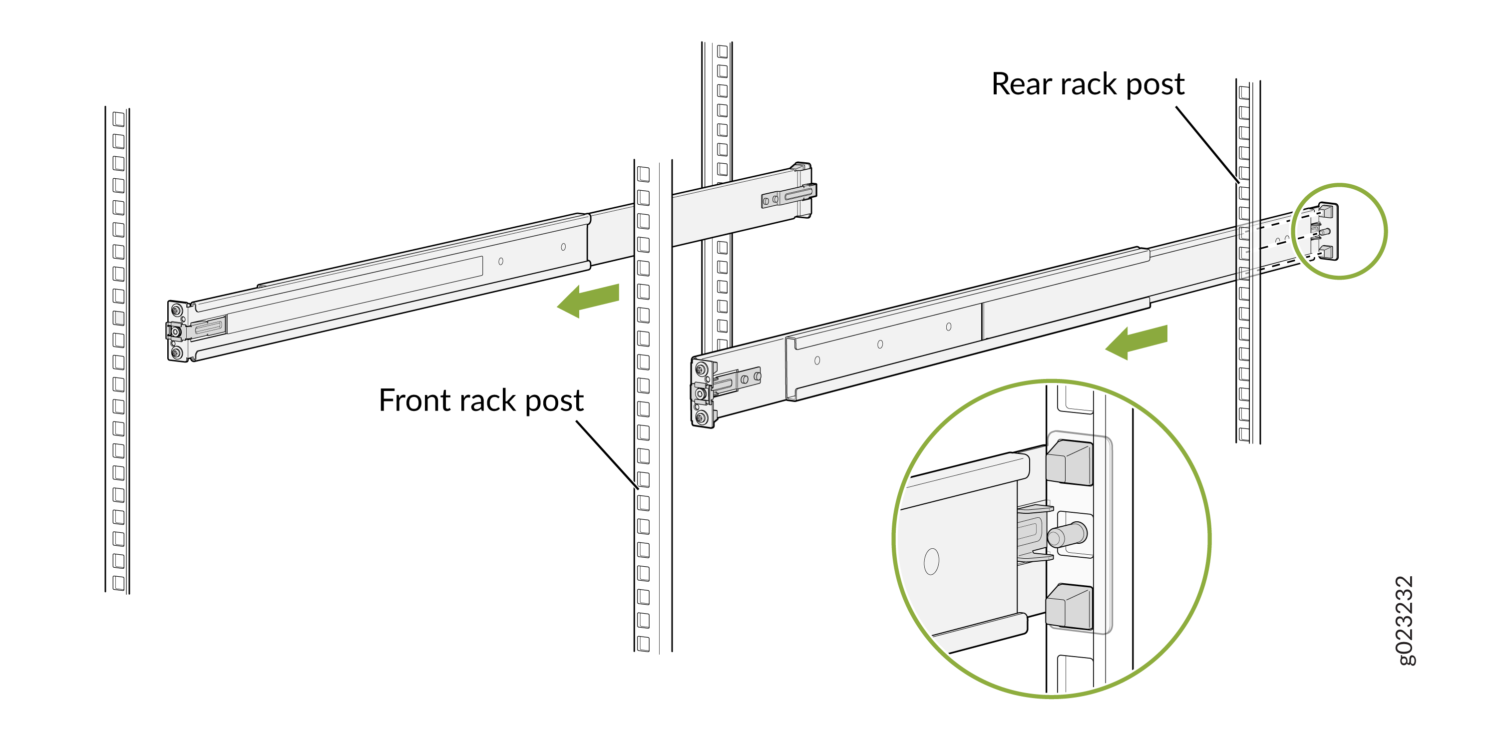
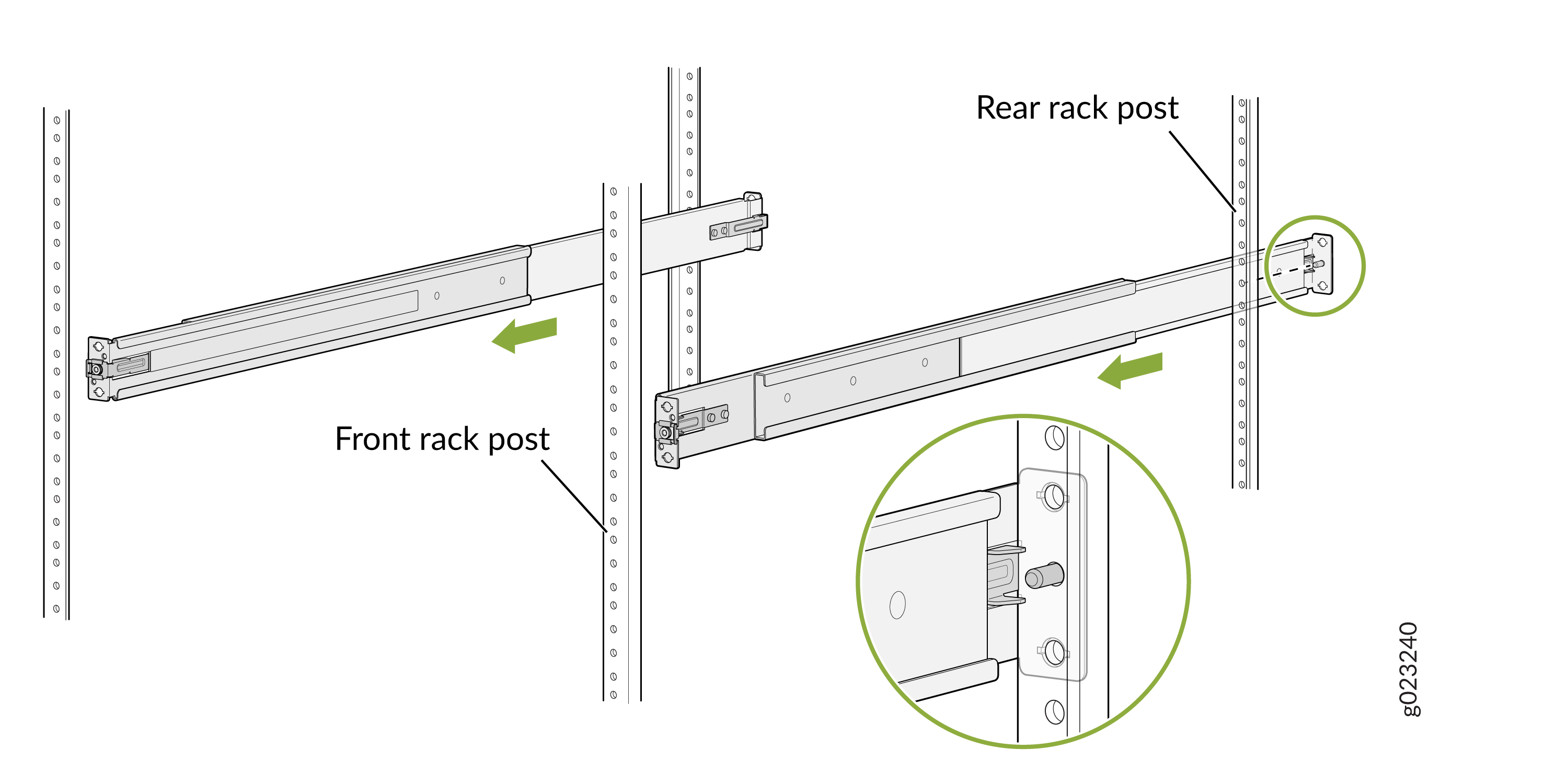
Assemble the mounting rails by sliding the rear floating rails into the
front rails.
Figure 36: Assemble the Mounting Rails
-
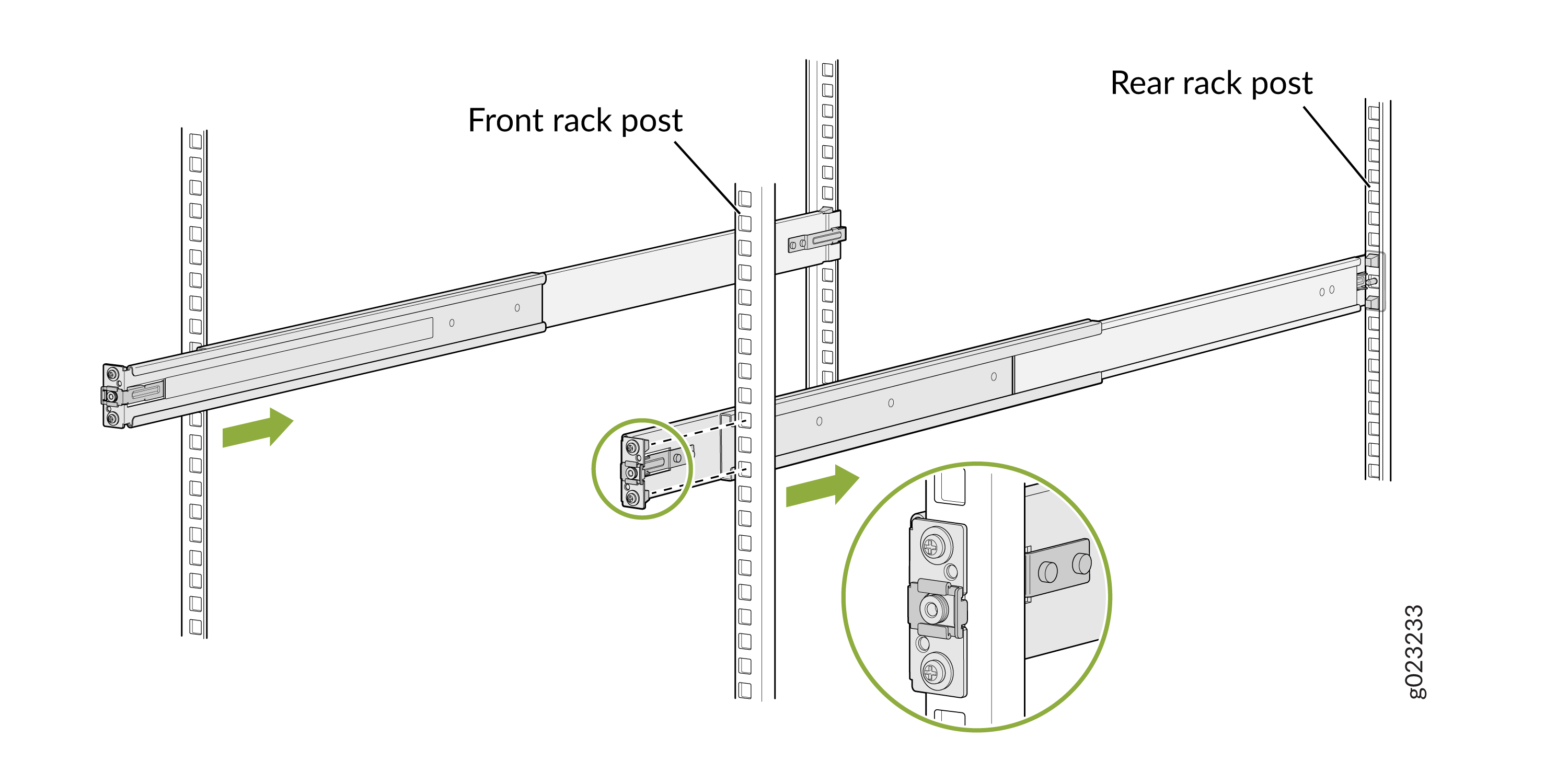
Install the mounting rails on the rack:
-
Align the guide blocks of the rear mounting rails with the
rear-post holes. Pull the rear mounting rails toward the front
of the rack to lock the rails in place. You will hear a distinct
click sound when the latch locks into the corresponding rack
holes.
Figure 37: Install the Rear Mounting Rails
-
Align the guide blocks of the front mounting rails with the
front-post holes. Push the front mounting rails toward the rear
of the rack to lock the rails in place. You will hear a distinct
click sound when the latch locks into the corresponding rack
holes.
Figure 38: Install the Front Mounting Rails
-
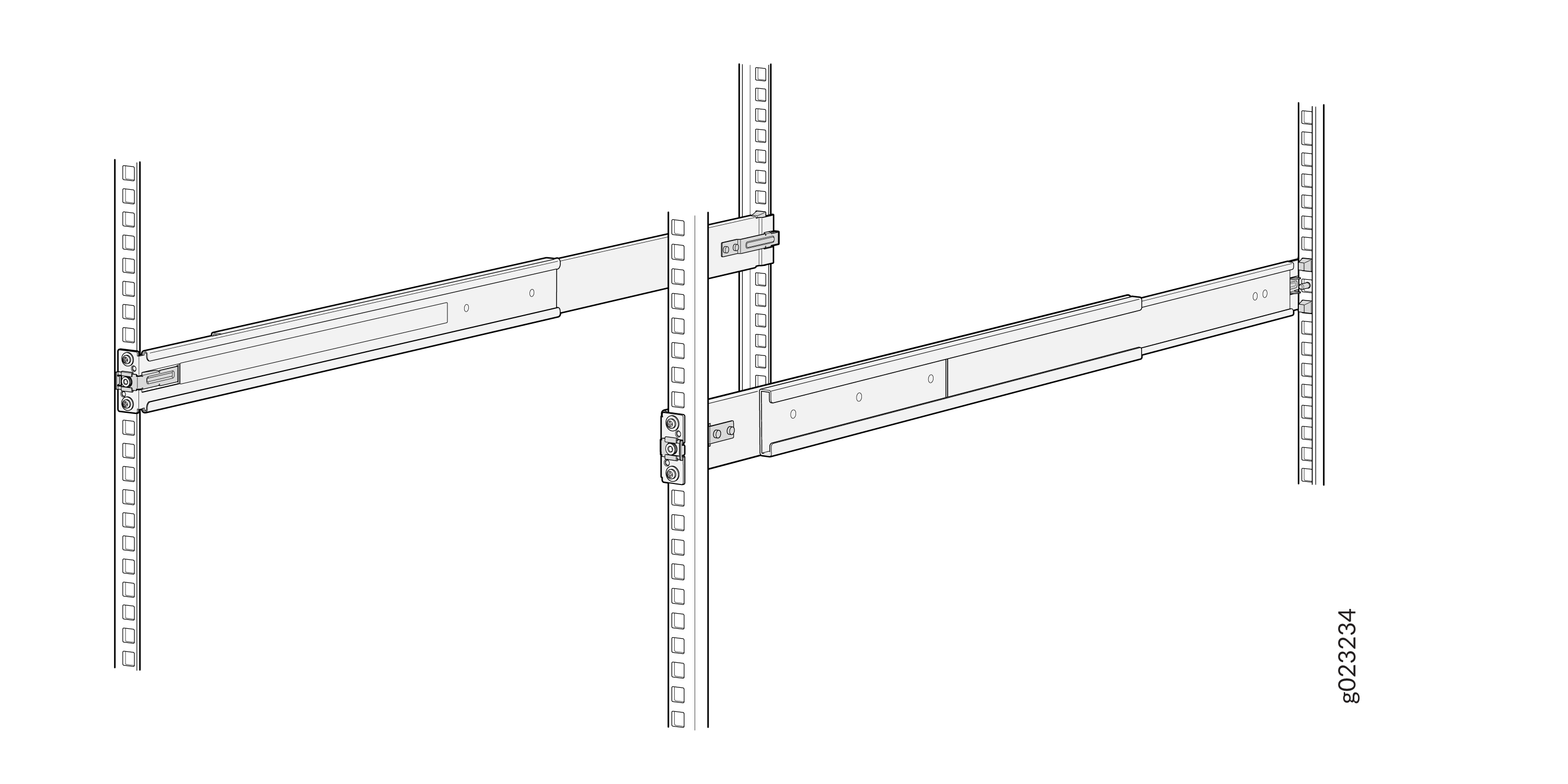
Visually ensure that the front and rear latches are locked into
place on the mounting rails. The mounting rails should be
securely installed on the rack.
Figure 39: Mounting rails secured on the rack
-
Align the guide blocks of the rear mounting rails with the
rear-post holes. Pull the rear mounting rails toward the front
of the rack to lock the rails in place. You will hear a distinct
click sound when the latch locks into the corresponding rack
holes.
-
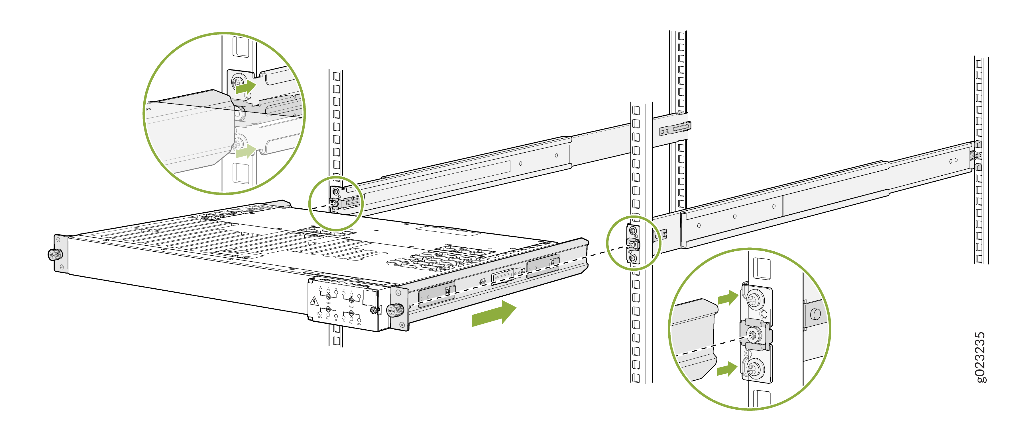
Lift the switch and position it in the rack, aligning the side
mounting-brackets with the mounting rails. Slide the switch into the channels
of the rack mounting rails.
Figure 40: Slide the Switch into the Rack
-
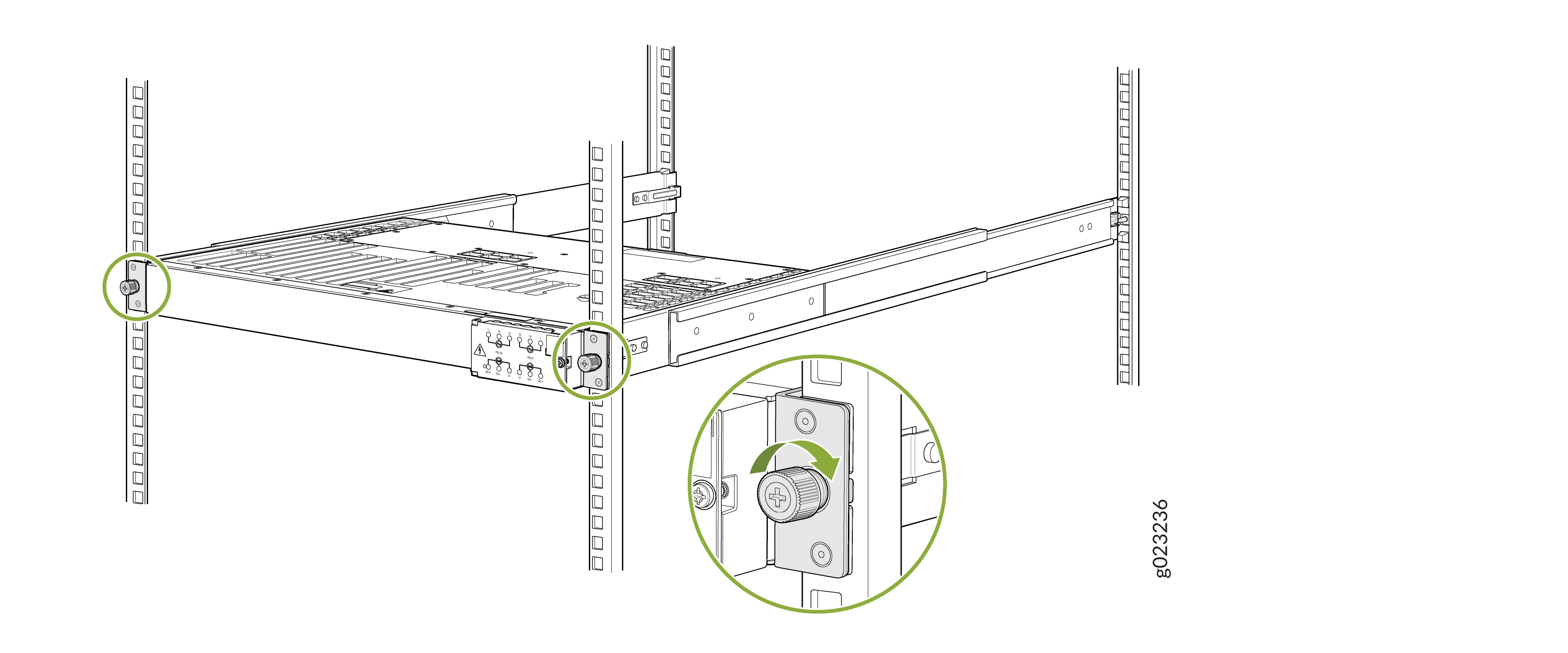
Tighten the two thumbscrews to secure the switch.
Figure 41: Tighten the Thumbscrews
Mount your Switch by Using the EX4100-H-4P-TL-RMK Tool less Rack Mount Kit on a Threaded-Hole 4-Post Rack
Ensure that you have the following tools and parts available:
-
An ESD grounding strap—not provided.
-
A Number 1 Phillips (+) screwdriver—not provided.
-
A Number 2 Phillips (+) screwdriver—not provided.
-
Eight screws to attach the mounting rails to the rack posts—not provided.
-
A pair of side mounting brackets that attach to the switch chassis—provided with the rack mount kit.
-
A pair of mounting front and rear rails that attach to the rack posts—provided with the rack mount kit.
To mount the switch on a four-post rack with threaded holes:
-
To attach the side mounting brackets to the switch chassis, align the
keyholes on the mounting brackets over the shoulder screws on the switch
chassis. Slide the mounting brackets toward the rear of the switch
chassis.
Figure 42: Attach the Side Mounting Brackets
-
Assemble the mounting rails:
-
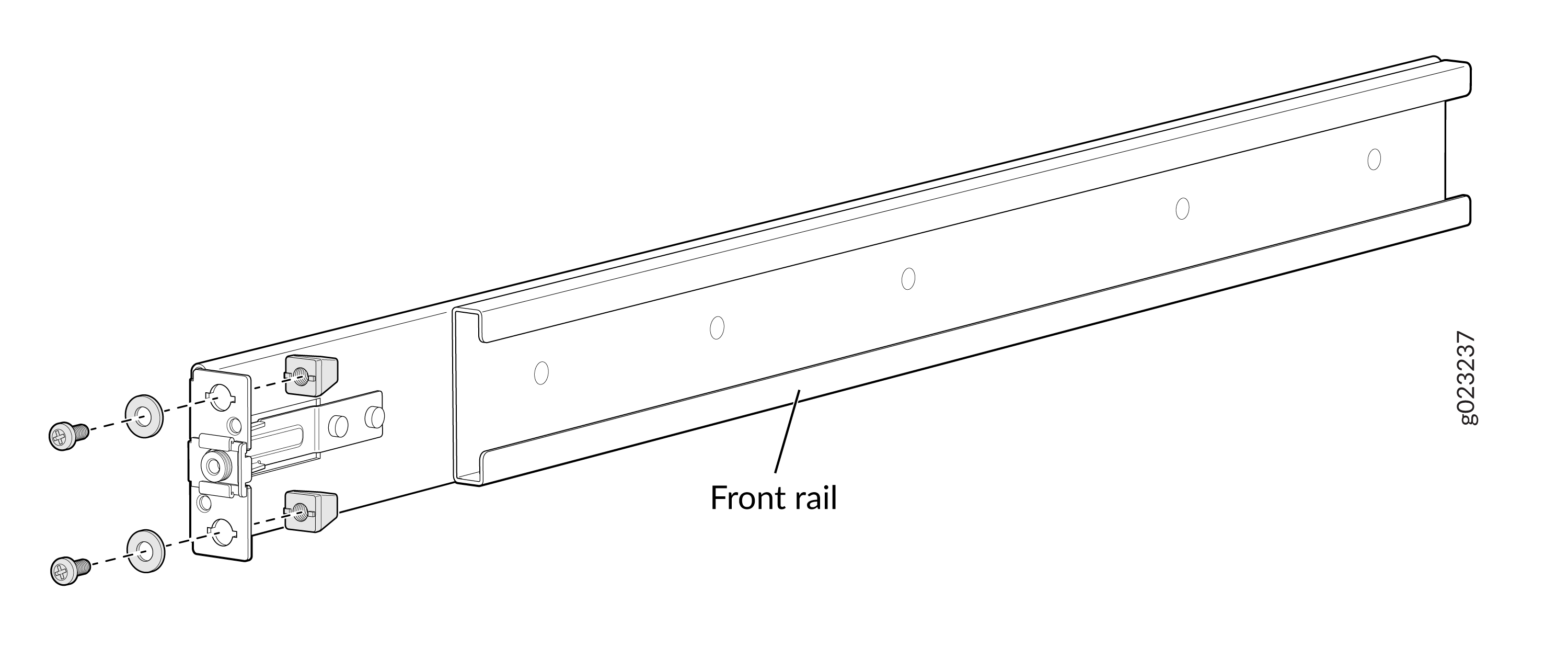
Remove the guide blocks from the front mounting rails by
loosening the screws and washers using recommended torque of 4.5
+/- 0.5 Lb.in.
Figure 43: Removing the Guide Blocks from the Front Mounting Rail
-
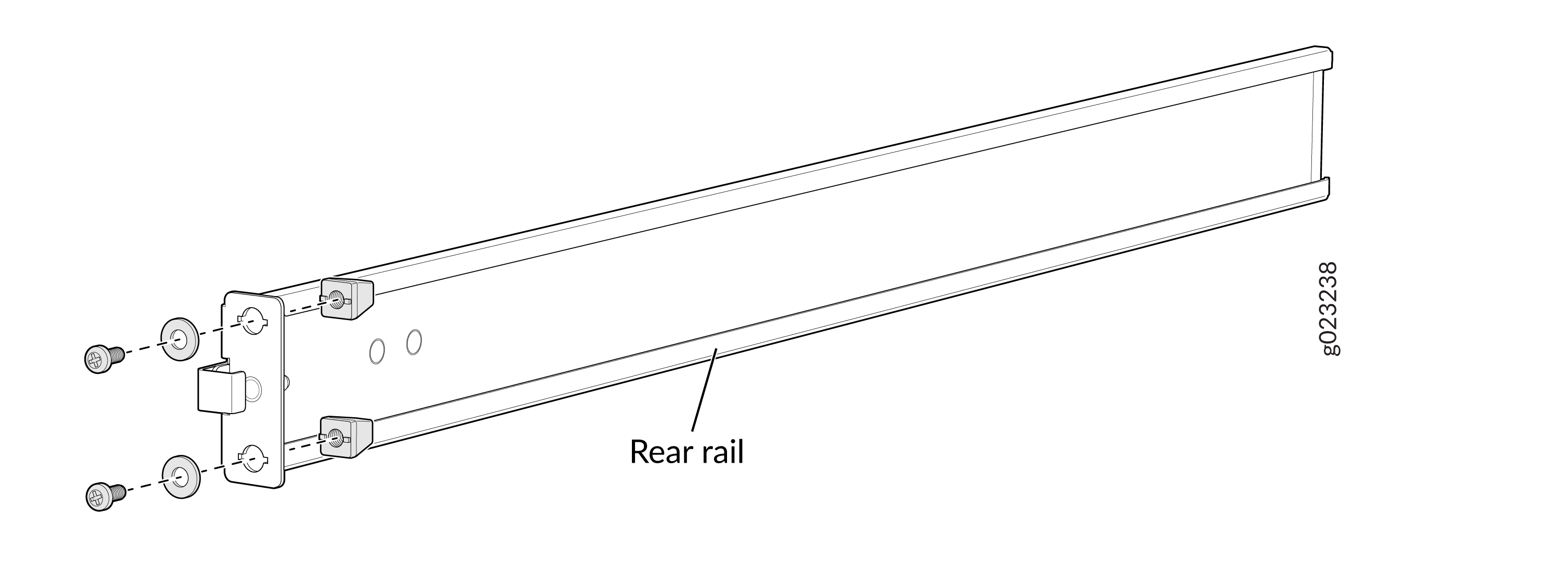
Remove the guide blocks from the rear mounting rail by
loosening the screws and washers.
Figure 44: Removing the Guide Blocks from the Rear Mounting Rail
-
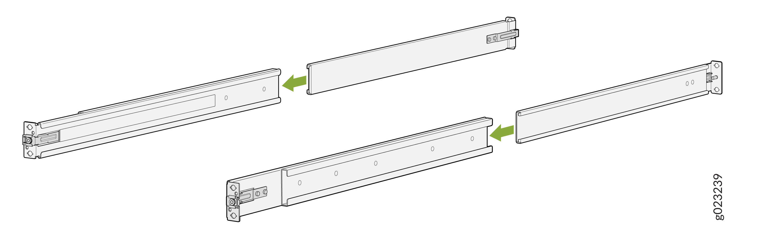
Slide the rear floating rails into the front rails.
Figure 45: Assemble the Mounting Rails
-
Remove the guide blocks from the front mounting rails by
loosening the screws and washers using recommended torque of 4.5
+/- 0.5 Lb.in.
-
Install the mounting rails on the rack:
-
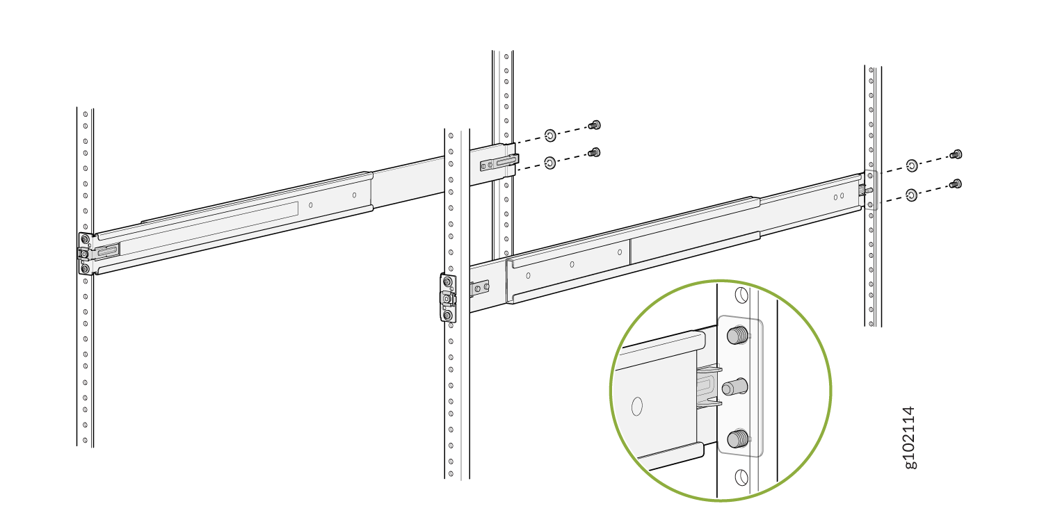
Insert the guide pin of the rear mounting rails into the
rear-post holes. Pull the rear mounting rails toward the front
of the rack to lock the rails in place. You will hear a distinct
click sound when the latch locks into place.
Figure 46: Install the Rear Mounting Rails
-
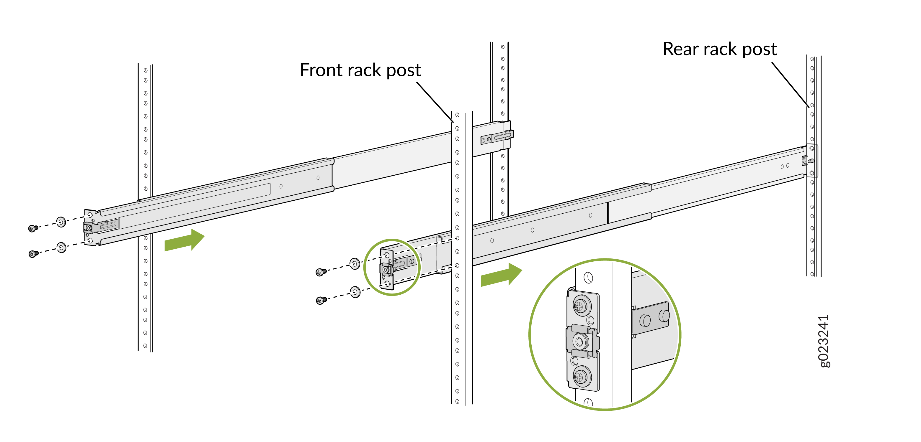
Insert the guide pin of the front mounting rails into the
front-post holes. Push the front mounting rails toward the rear
of the rack to lock the rails in place. You will hear a distinct
click sound when the latch locks into place. Secure the front
mounting rails to the front rack post by using screws
appropriate for your rack threaded size (not provided).
Figure 47: Install and Secure the Front Mounting Rails
-
Secure the rear mounting rails to the rear rack post by using
screws appropriate for your rack threaded size (not
provided).
Figure 48: Secure the Rear Mounting Brackets
-
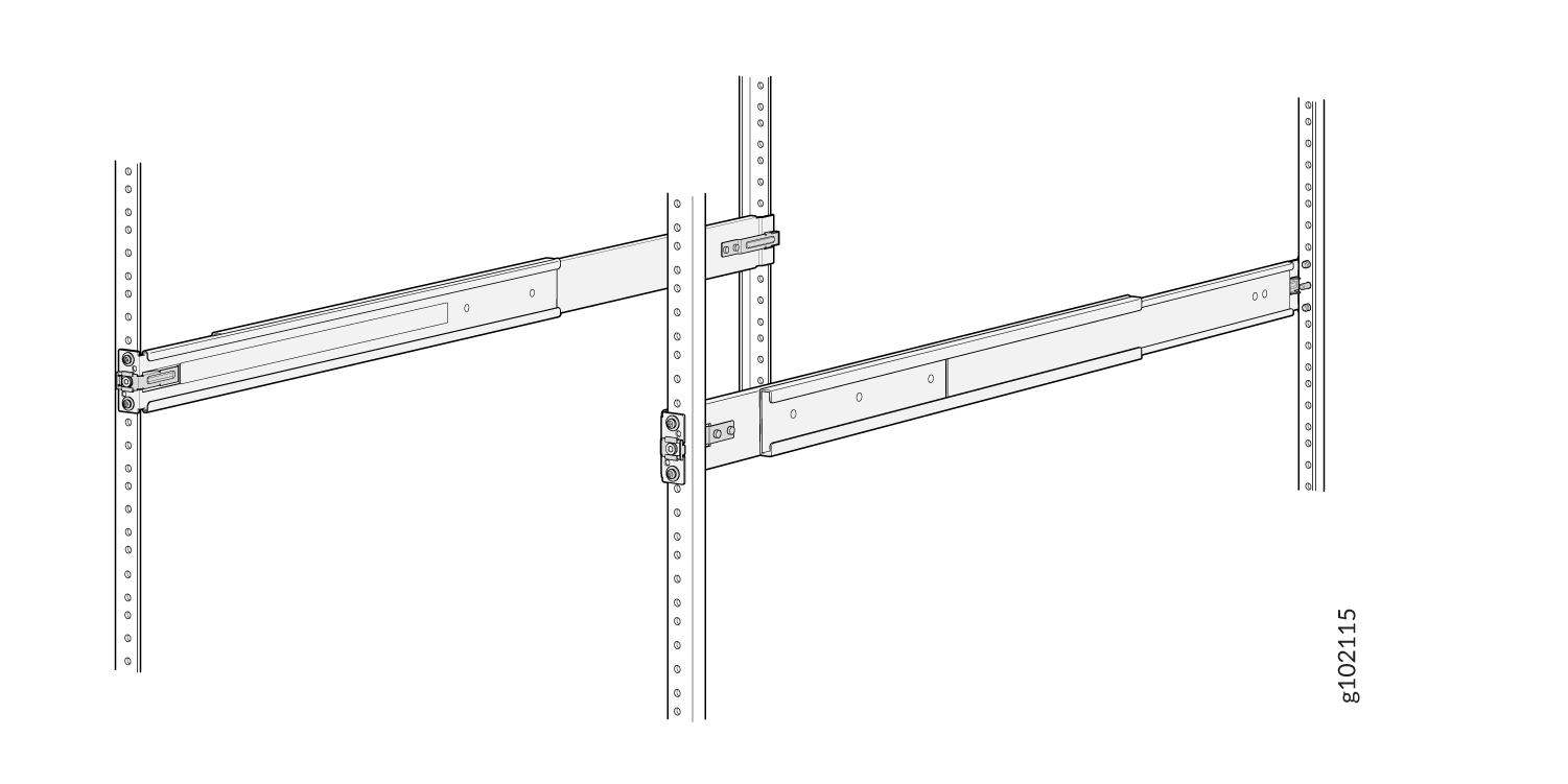
Visually ensure that the front and rear latches are locked into
place on the mounting rails. The mounting rails should be
securely installed on the rack.
Figure 49: Mounting Rails Installed and Secured
-
Insert the guide pin of the rear mounting rails into the
rear-post holes. Pull the rear mounting rails toward the front
of the rack to lock the rails in place. You will hear a distinct
click sound when the latch locks into place.
-
Lift the switch and position it in the rack, aligning the side mounting
brackets with the mounting rails. Slide the switch into the channels of the
rack mounting rails.
Figure 50: Slide the Switch into the Rack
-
Tighten the two thumbscrews to secure the switch.
Figure 51: Tighten the Thumbscrews
Attaching the Physical Security Lock to the EX4100-H-12MP Switch
-
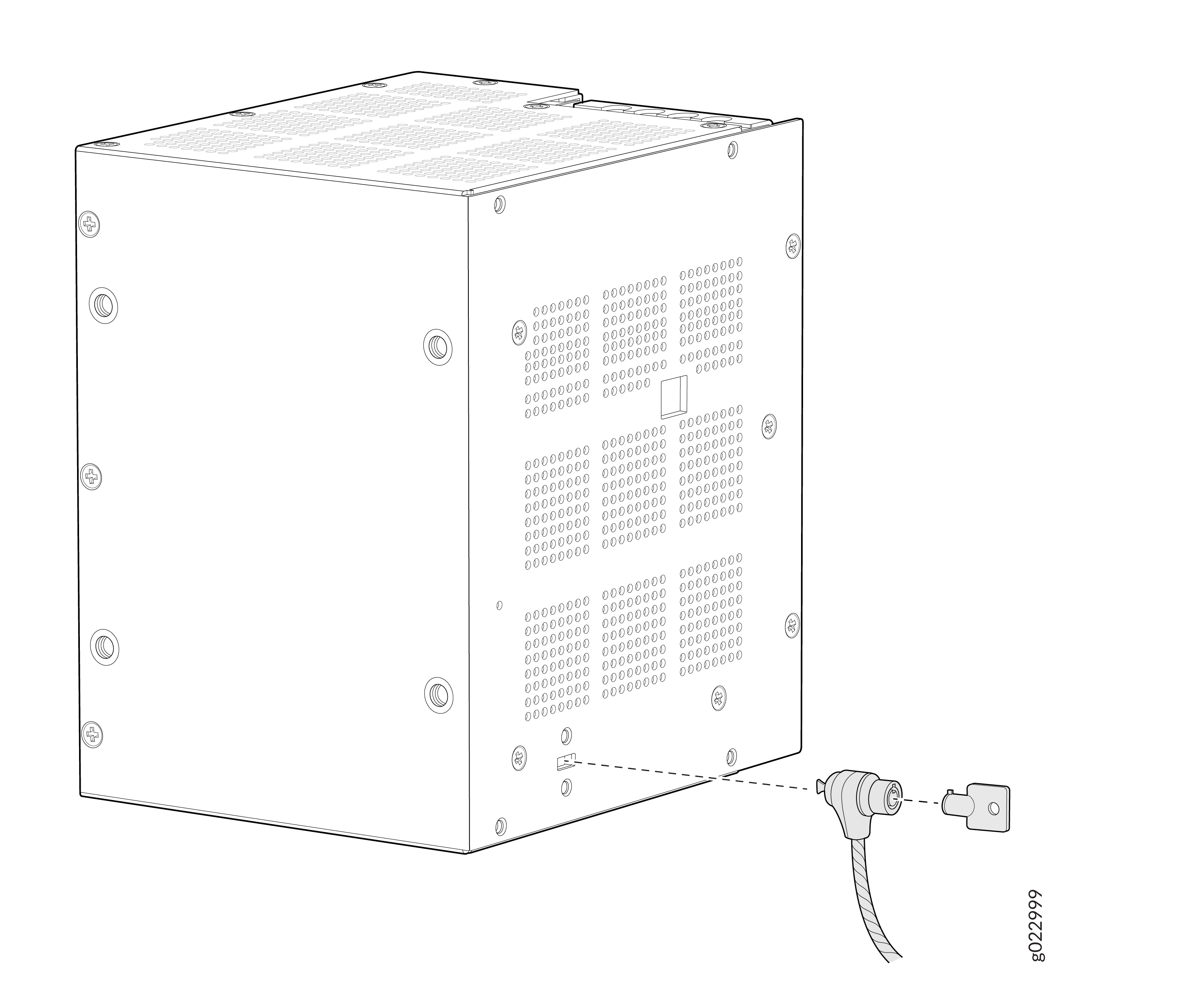
Insert the lock into the security slot on the switch chassis.
Figure 52: Insert the lock into the security slot on the switch chassis
-
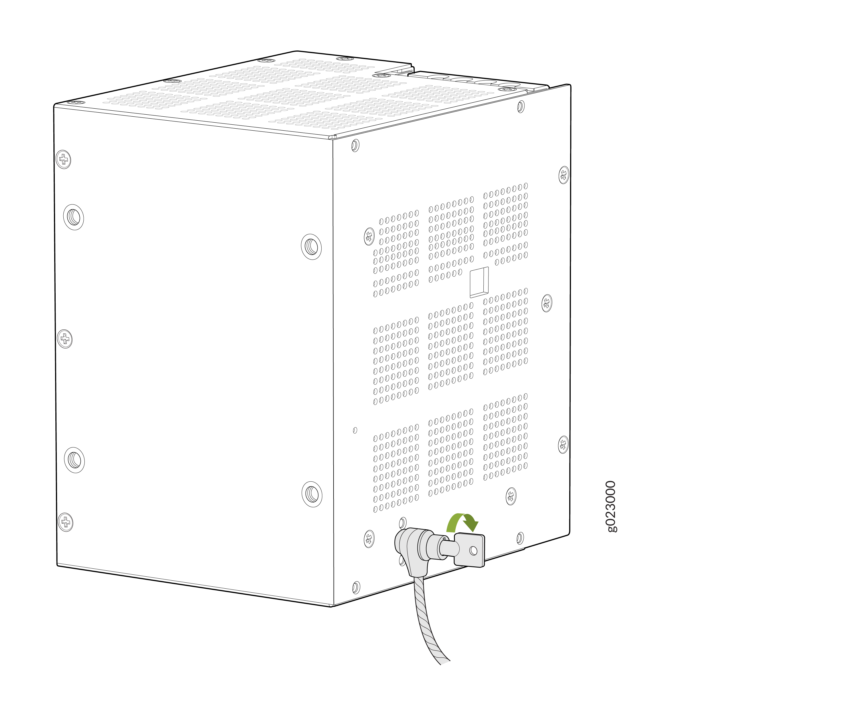
Set the lock to the locked position using the key.
Figure 53: Set the lock to the locked position using the key
-
Insert the lock into the security slot on the PSU.
Figure 54: Insert the lock into the security slot on the PSU
-
Set the lock to the locked position using the key.
Figure 55: Set the lock to the locked position using the key
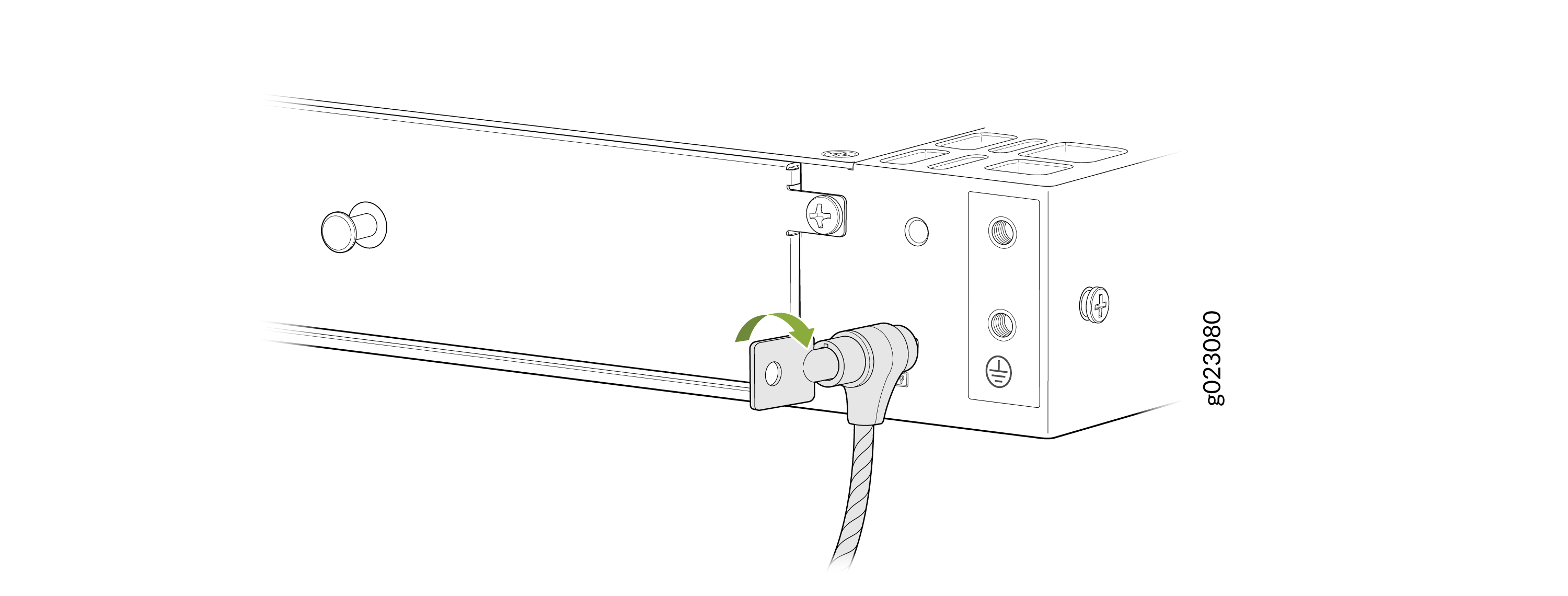
Attaching the Physical Security Lock to the EX4100-H-24MP and EX4100-H-24F Switch
-
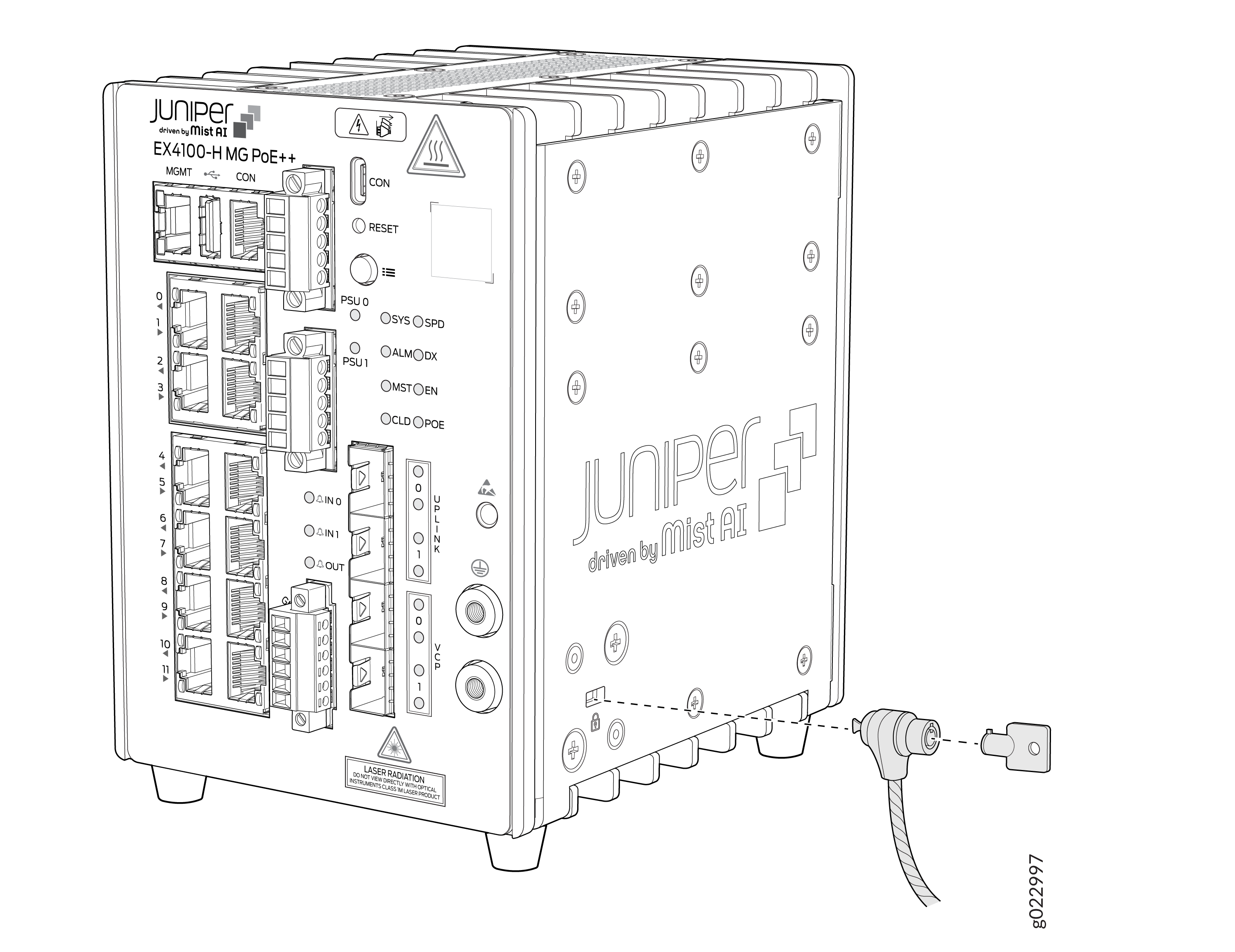
Insert the lock into the security slot on the switch chassis.
Figure 56: Insert the lock into the security slot on the switch chassis of EX4100-H-24MP
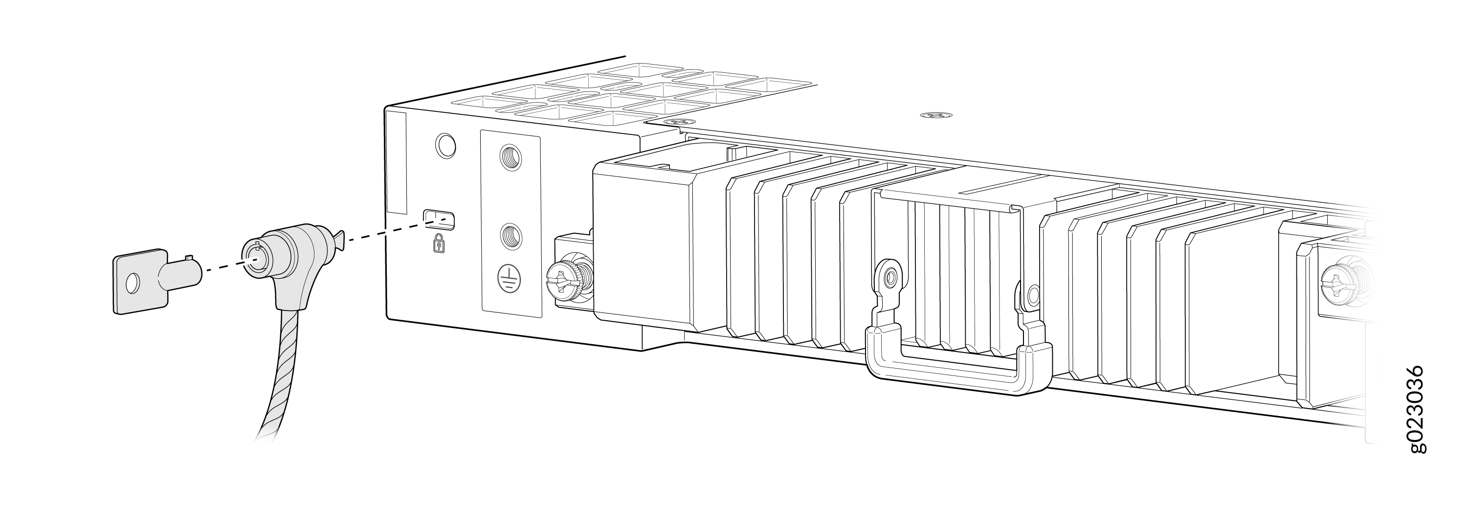 Figure 57: Insert the lock into the security slot on the switch chassis of EX4100-H-24F
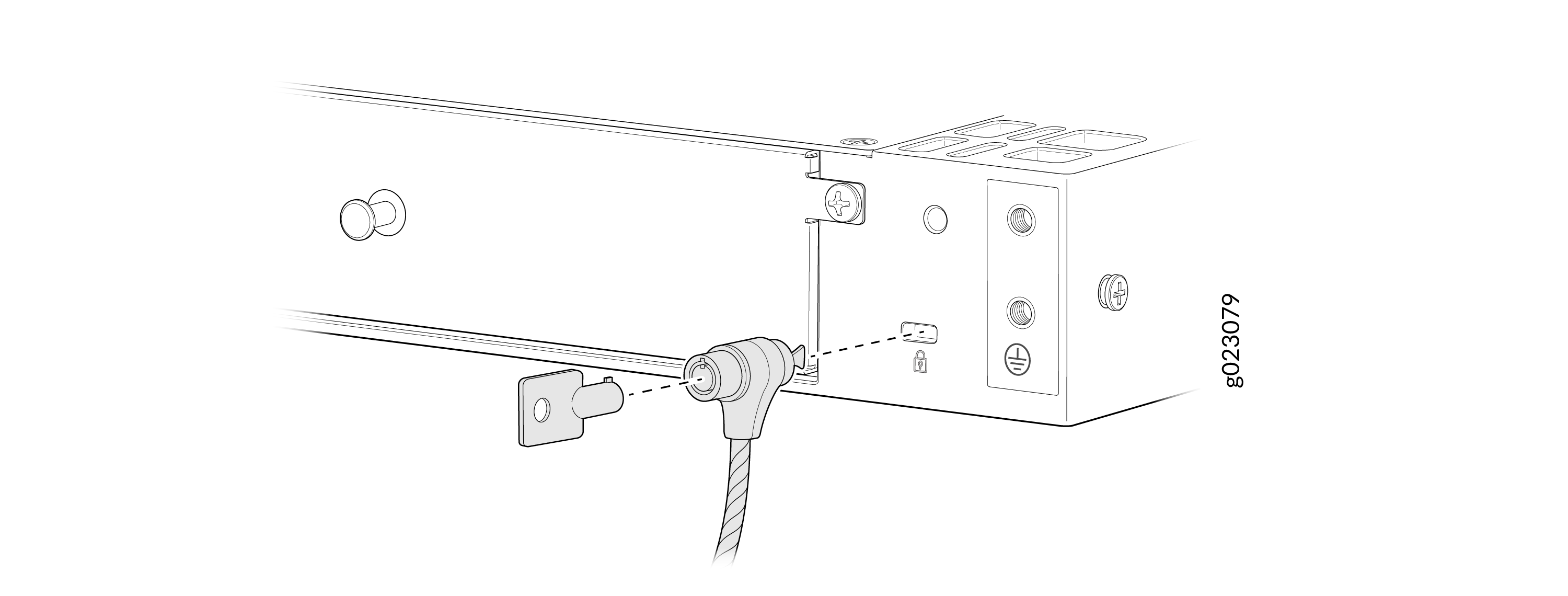
-
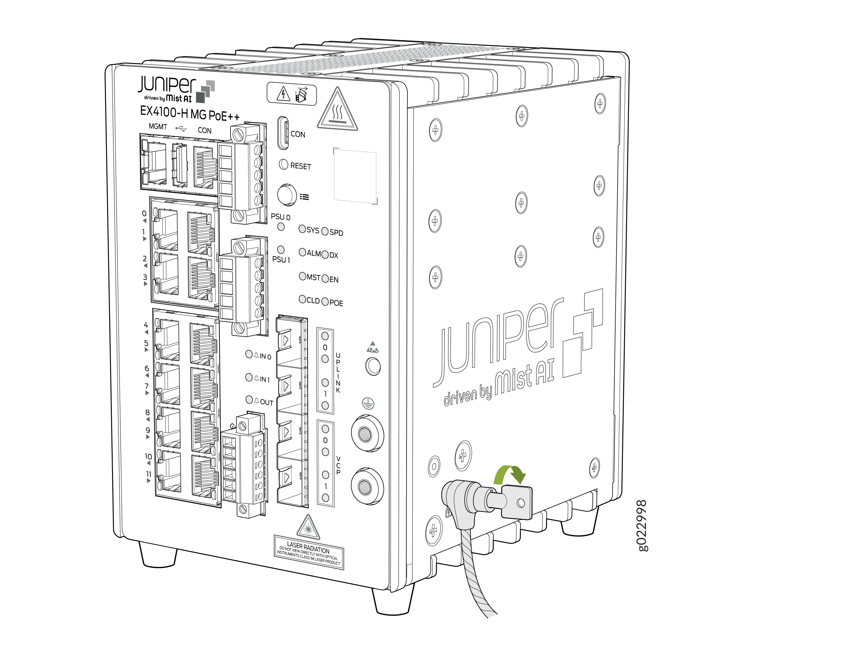
Set the lock to the locked position using the key.
Figure 58: Set the lock to the locked position using the key on EX4100-H-24MP
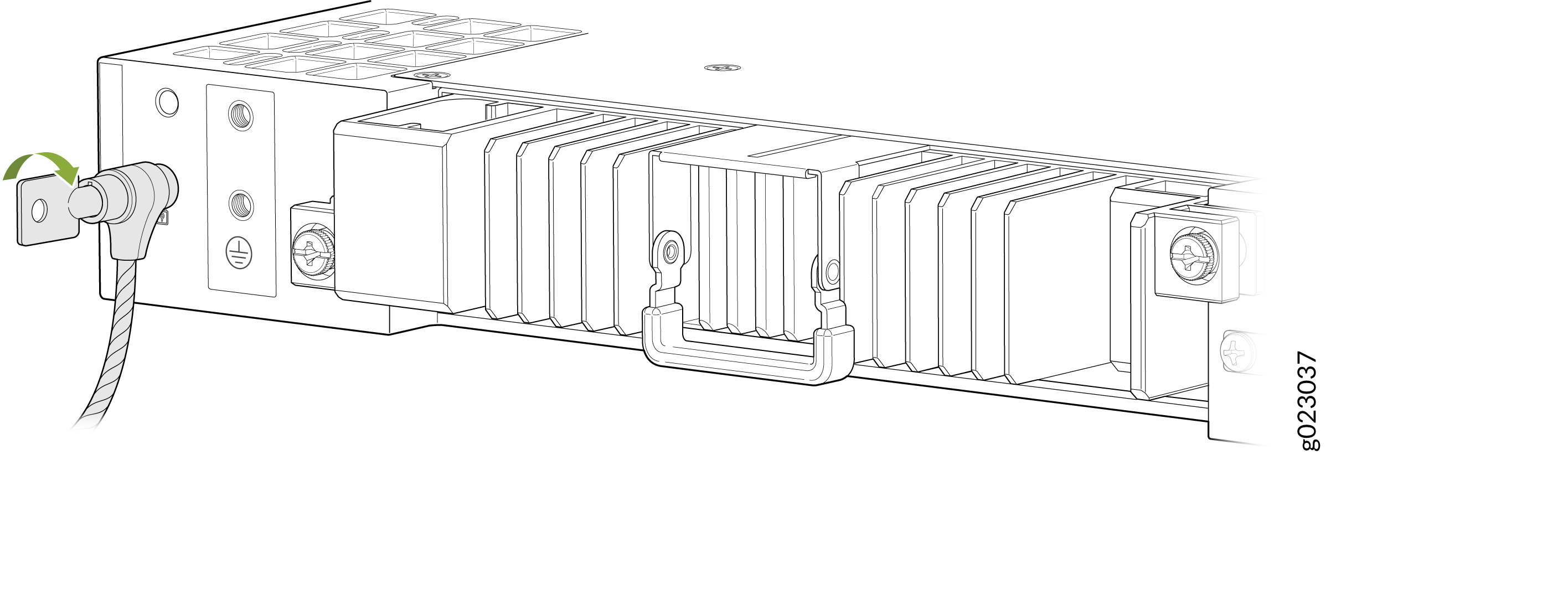 Figure 59: Set the lock to the locked position using the key on EX4100-H-24F