Internet Exchange Point Overview
An Internet Exchange Point (IXP) is a Layer 2 network, for example a Layer 2 MPLS-based service, like VPLS or EVPN, that facilitates interconnection between Internet Service Providers (ISPs) using the Border Gateway Protocol (BGP) protocol to exchange routing information.
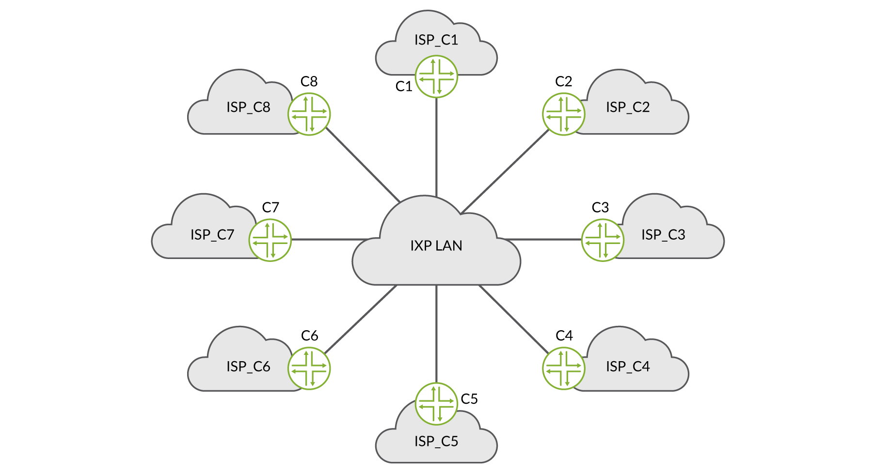
At its core, an IXP is essentially one or more physical locations containing interconnected switches that move traffic between the different connected networks (generally referred to as members in an IXP context). The network is referred to as the IXP LAN or peering LAN. See Figure 1.
Members share the costs of maintaining the physical infrastructure and associated services via various charging schemes, but in almost every case the membership costs are a fixed monthly fee depending on the port speed and number of ports a member uses.
Traffic exchange between two members on an IXP is facilitated by the BGP routing configurations between them (peering session). Members choose to announce routes via the peering relationship – either routes to their own addresses, or routes to addresses of other networks that they connect to (for example, customers).
The other party to the peering relationship can then apply route filtering where it chooses to accept those routes and route traffic accordingly, or ignore those routes and use other routes to reach those addresses.
Which routes to advertise, or advertisements to accept or filter from a member, is covered in greater detail in Day One: Deploying BGP Routing Security(see: https://www.juniper.net/us/en/training/jnbooks/day-one/deploying-bgp-routing-security/).
The Economics of an Internet Exchange Point
You could say that the goal of an IXP is to reduce the portion of traffic an ISP will deliver via their upstream transit providers, thereby, amongst other things, potentially reducing the average per-bit delivery cost of traffic. Furthermore, the increased number of available paths improves routing efficiency and fault tolerance. Additionally, and sometimes more importantly, goals could be reducing latency, providing shorter network paths, and increasing or providing redundancy.
IXPs exhibit the characteristics of what economists call the Network Externality Effect (https://en.wikipedia.org/wiki/Network_effect), or, the value of the product or service is proportional to the number of users of the product or service. Internet exchanges are a special case of this effect; the value of an exchange point is not purely the number of participants, but a slightly more complex calculation including the number and uniqueness of the routes and the volume of traffic peered. Since the value of the IXP to an ISP is proportional to the amount of traffic the ISP can exchange in peering relationships at the IXP, the value of the IXP to the peering population follows the network externality graph as shown in Figure 2.
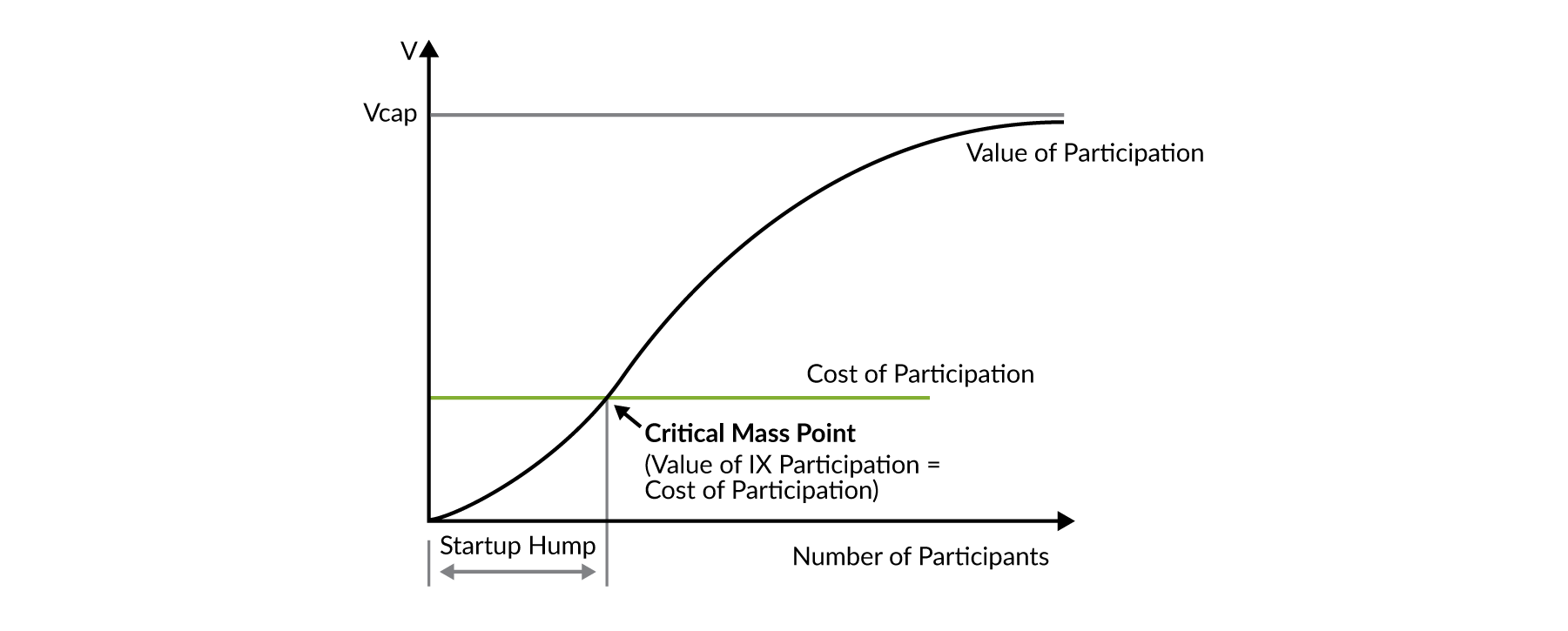
Figure 2. illustrates a plot of the value of the IXP (Vcap) as a function of the number of participants. As more participants connect to the exchange point, more participants can peer with each other. From the point of view of the participants, the value of the exchange point increases with each potential peer.
Peering Relationships
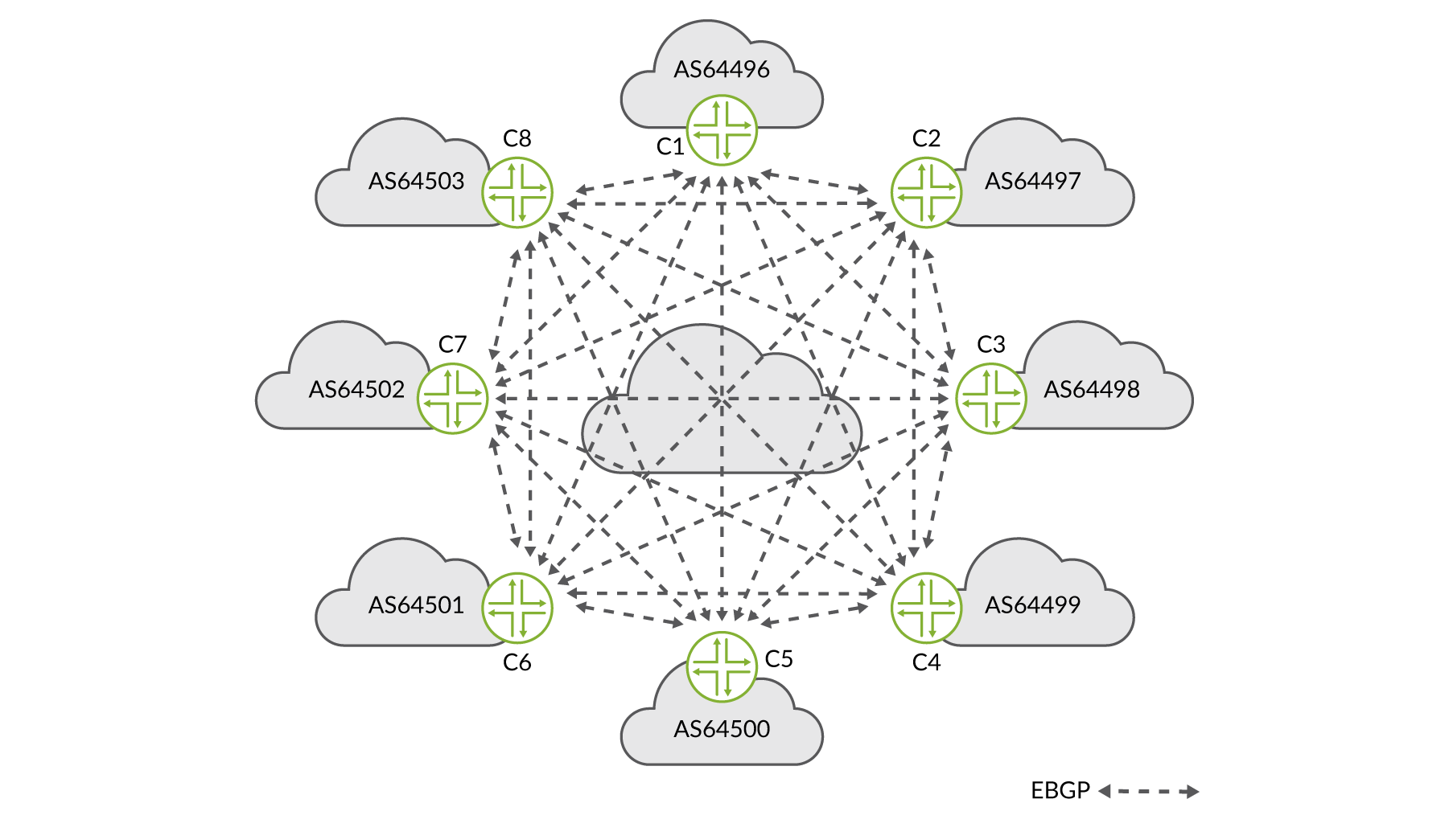
While bilateral peering (negotiated and established between exactly two members) sessions were previously the most common means of exchanging routes, the overhead associated with dense interconnection can cause substantial operational scaling problems for members of larger IXPs.
Multilateral interconnection is a method of interconnecting members using a “external brokering” system, commonly referred to as a route server and typically managed by the IXP. Each multilateral interconnection participant (referred to as a route server client) announces its routes to the route server using External Border Gateway Protocol (EBGP). The route server, in turn, transparently forwards this information to each route server client connected to it.
What is a Route Server?
The barrier of entry for an organization to become a member and begin peering on an IXP is generally quite low. At least a single physical or remote (backhaul) port connected to the IXP peering LAN and an assigned IP address from the IX LAN subnet is needed. It is then possible to configure BGP peering with anyone else on the peering LAN who is willing to peer.
To do so, you have to manually configure those BGP peering sessions with whomever you wish to peer with. This is called bilateral interconnection, meaning there is one session between you and the peer, and only you and the specific peer exchange route advertisements.
Imagine a large IXP with many (100+) members. This can very quickly become cumbersome. In particular when filtering per peer on correct route advertisements (for example based on an Internet Routing Registry: https://en.wikipedia.org/wiki/Internet_Routing_Registry), prefixes, AS-path, etc., which you should do. It is a no-brainer to use an easier solution when one is available.
To avoid configuring and maintaining 10s or 100s (some of the larger IXPs have over 500 members or members with multiple connections) of individual EBGP sessions with each member, the smarter option where you only need a couple of sessions, is to use the route servers. Route servers are typically offered by the IXP as a service to its members.
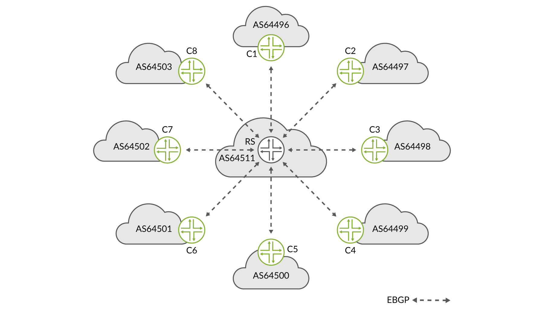
One BGP session between the ISP’s router and the route server is all that is required to announce to, and receive routes from, all other members of the IXP (as shown in Figure 4). Obviously, you will only be able to exchange routing information with members who also have a BGP session with the route servers. Thus it provides an alternative to full mesh peering among the members who have a presence at the IXP.
Some ISPs will rely solely on the route server session(s), while others will use it as a backup to their existing EBGP peerings on the IXP fabric. Most IXPs will have redundant route servers and suggest that members peer with both.
Peering with the IXP’s route servers could offer the member additional benefits such as communities to filter on. For example, their originating country or the originating data center.
The route server provides:
EBGP route reflection with customized policy support for each service provider at the IXP.
Reduced configuration complexity (thus maintaining just a few BGP sessions instead of hundreds).
Reduced CPU and memory requirements on each member router; you will still receive all the prefixes but won’t need all the separate BGP peering sessions.
Reduced administrative overhead expense incurred by individualized peering agreements.
Additional filter options (IRRdb, RPKI, predefined BGP communities) without the need to implement those yourself.
Ability to send and receive traffic via the IXP from day one (no need to wait for all the individual peerings to be arranged).
A possible backup path; when your BGP session to another member becomes inactive, there is a possibility that you can still reach the members network via routes learned from the route servers.
The route server itself does not participate in actual traffic forwarding, it only provides routing information (AS-PATHs, routes, communities, next hops, etc.). From that perspective, as no forwarding hardware is needed, a route server can easily be a virtual machine (VM) or container instead of a physical box. Also, peering with a route server does not mean that you have to accept all routes from all other route server participants, or that you have to advertise all your routes to every other member. How do you configure that? Read on…
BGP Routing Information Base (RIB)
Throughout this book different types of routing information bases (RIBs) are mentioned. This paragraph prepares you for those. Generally speaking, a RIB holds routing information but there are three RIBs within a BGP speaker that are relevant:
Adj-RIB-In: Stores routing information learned from inbound BGP UPDATE messages. It contains routes that are available as an input to the BGP decision process.
Loc-RIB: Contains routing information after applying import policies to the routing information stored in Adj-RIBs-In.
Adj-RIB-Out: Stores the information that is selected for advertisement to peers. The routing information stored in the Adj-RIB-Out will be used in outbound UPDATE messages and advertised to its peers.
In summary, the Adj-RIB-In contains unprocessed routing information that has been received from peers. Loc-RIB contains the routes that have been selected by the local BGP speaker’s decision process, and the Adj-RIB-Out contains the routes for advertisement to specific peers by means of UPDATE messages.
Route Reflector Versus Route Server Versus Route Collector
Just for clarity, and to make sure you are on the same page as we are in this book, let’s define route reflector, route server, and route collector. The major distinction between route reflectors and route servers lies in the IBGP semantics of route reflectors versus the EBGP semantics required for route servers. The route collector is a unique case.
Route Reflector
A route reflector is often used to eliminate the need for a
full-mesh of sessions among IBGP speakers. The route reflector must
know when to reflect a peer’s announcement to another peer,
in order to preserve IBGP semantics. The route reflector sends the
best path in its Loc-RIB to all clients (except the one it learned
the routes from). The route reflector will not typically modify the
attributes, unless told to by setting the next-hop-self knob or local configured policy, but that is the default behavior
for IBGP.
Route Server
A route server plays a similar role, transparently (attributes are not changed), but in this case for EBGP speakers, it must be able to suppress its own (possibly private) ASN from being prepended to the advertised routes.
It also maintains a RIB unique to each of its clients (per client Loc-Rib), whose policy specific to that client can be applied. The client gets its updates from that RIB, not from the global Loc-RIB.
Route Collector
The stranger in our midst is the route collector, as it does not forward any packets and also does not announce any prefixes to anyone. Its purpose, as its name more or less reveals, is to collect routing information. By doing so, the route collector and its accessory tools act like a looking glass to provide (in most cases) a public view of the ‘routing information’ known at ‘a point in the network’. In an IXP context, the information provided by a route collector would provide useful information for:
IXP members to check functionality of BGP filters
Prospective members to evaluate the value of joining the IXP
The operations community for troubleshooting purposes.
Going forward, we cover route servers in this book.
Route Server Attribute Transparency
As a route server primarily performs a brokering service, modification of attributes could cause route server clients to alter their BGP decision process for received prefix reachability information, thereby changing the intended routing policies of exchange participants. (See the Juniper TechLibrary for more detail: https://www.juniper.net/documentation/en_US/Junos/topics/reference/general/routing-protocols-address-representation.html.)
Contrary to the ordinary EBGP route handling rules, route servers
do not update well-known BGP attributes by default, (unless explicitly
configured) (https://training.apnic.net/wp-content/uploads/sites/2/2016/11/eROU04_BGP_Attributes.pdf
Next_Hop attribute
AS_Path attribute
Multi_Exit_Descriminator
Communities
Path Hiding Mitigation in Route Server Deployments
In the traditional bilateral interconnection model, per-client policy control to a third-party exchange participant is accomplished either by not engaging in a bilateral interconnection with that participant or by implementing outbound filtering on the BGP session towards that participant. However, in a multilateral interconnection environment, only the route server can perform outbound filtering in the direction of the route server client; route server clients depend on the route server to perform their outbound filtering for them.
Assuming the default BGP decision process is followed, when the same prefix is advertised to a route server from multiple route server clients, the route server will select a single path for propagation to all connected clients. If, however, the route server has been configured to filter the calculated best path from reaching a particular route server client, then that client will not receive a path for that prefix, although alternate paths received by the route server might have been policy compliant for that client. This phenomenon is referred to as path hiding.
Using the example illustrated in Figure 5, four customer routers, depicted by C [1-4] in four different BGP autonomous systems (AS) exchange routes. C1 in AS64496 does not directly exchange prefix information with either C2 in AS644967, or C3 in AS64498 at the IXP, but only interconnects with C4 in AS64499. The lines between AS64496, AS64497, AS64498, and AS64499 represent interconnection relationships, whether via direct (bilateral) EBGP sessions or using the route server (multilateral).
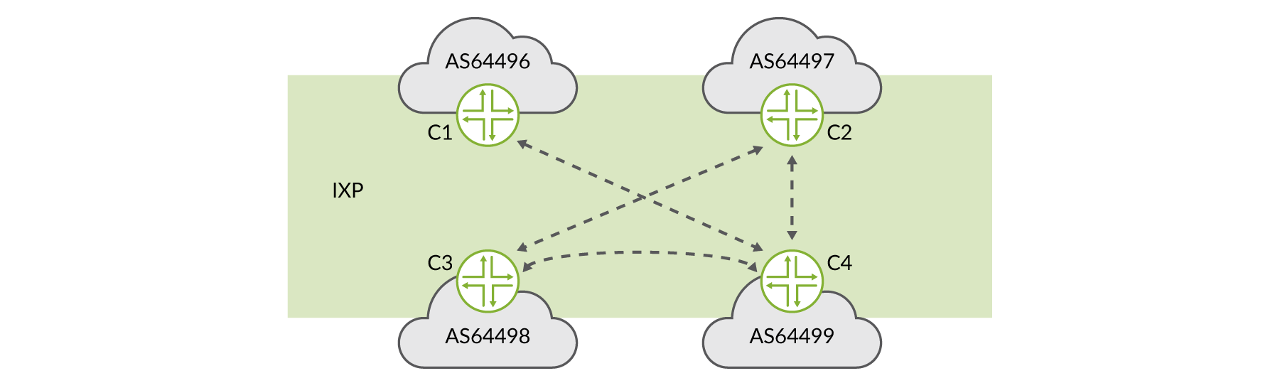
Let’s say a prefix is advertised to the route servers from both AS64497 and AS64499, and the route via AS64497 was preferred according to the BGP decision process on the route server. All would be fine and the prefix is reachable. The exception occurs when AS64497’s policy prevented the route server from sending the path to AS64496, so AS64496 would never receive a path to this prefix, even though the route server also received a valid alternative path via AS64499. This happens because the BGP decision process is performed only once on the route server for all clients
While there are several options available to mitigate path hiding (https://tools.ietf.org/html/rfc7947#section-2.3.2) in route server environments, Junos OS employs multiple route server-client RIBs (see Figure 6 and https://tools.ietf.org/html/rfc7947#section-2.3.2.1). The Juniper route server BGP implementation performs the per-client best path calculation for each set of paths to a prefix, using per-client Loc-RIBs, with path filtering implemented between the Adj-RIB-In and the per-client Loc-RIB. More details on this are provided later in this book.

Architecture of a Route Server Deployment
This section provides some conceptual ideas on how to set up and operate route servers in an IXP environment.
Per Route-Server Client Policy Using BGP Communities
Policy control is typically handled through the use of BGP communities. Prefixes sent to the route server are tagged with specific standard BGP communities (https://tools.ietf.org/html/rfc1997), extended communities (https://tools.ietf.org/html/rfc4360), or large communities (https://tools.ietf.org/html/rfc8092) attributes, based on predefined values agreed upon between the IXP and all IXP members. Currently there is no mutually agreed upon standard across IXPs for community usage, although some work has been done to define a standard, for example: https://tools.ietf.org/html/draft-adkp-grow-ixpcommunities-00.
In this case we use standard communities for the purpose of explaining. The usage of extended or large communities can have advantages.
BGP routes may be propagated to all other clients, a subset of clients, or no clients, depending on the values of the communities. This mechanism allows route server clients to instruct the route server to implement per-client export routing policies. As an example, IXP members may tag their routes with those shown in Table 1 to control policy via the route server.
Table 1: Example Standard BGP Communities for Controlling Per-Client Policy
Policy Description | BGP Community |
|---|---|
Block announcement of a route to a certain peer | 0:<peer-as> |
Announcement of a route to a certain peer | <rs-as>:<peer-as> |
Block announcement of a route to all peers | 0:<rs-as> |
Announcement of a route to all peers | <rs-as>:<rs-as> |
Redundancy
The purpose of an IXP route server implementation is to provide a reliable reachability brokerage service, therefore IXP operators generally deploy multiple route servers (see Figure 7).
It may be a good idea to also advertise routes between route servers to ensure reachability even if, or when, BGP sessions are down for specific IXP member routers on specific route servers, but not on others. While this event is likely to be quite rare, it’s worth carefully considering it when offering a route server-based service.
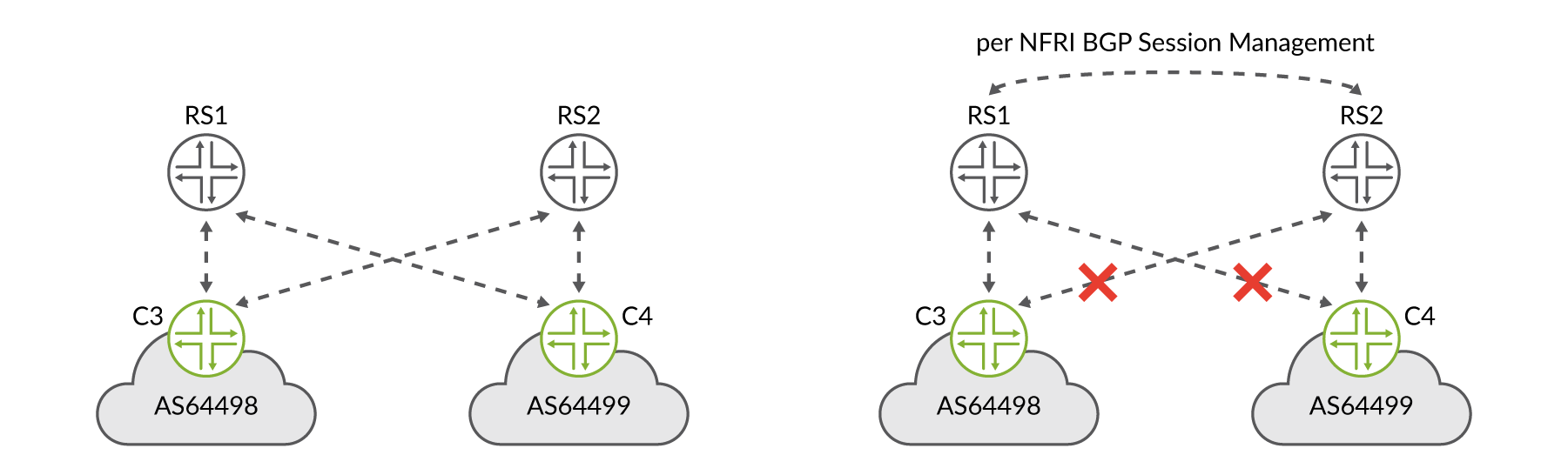
However, redundant route server deployments of this style may result in a bit more complexity in terms of session management between route servers as well as instance-import/export policies associated with Junos OS path mitigation techniques. In Figure 7, the right side depicts this extra complexity in the form of per Non-Forwarding Routing Instance (NFRI) BGP sessions and policy. Therefore, this has to be carefully evaluated. Most IXPs operate a set of two independent route servers as this seems to result in the best balance between redundancy and complexity.
Route Server Security Considerations
The following basic EBGP best practices are for your security considerations.
Generalized TTL Security Mechanism (RFC3682)
GTSM is designed to protect a router’s control plane from CPU-utilization based attacks. GTSM is based on the fact that the vast majority of protocol peerings are established between routers that are adjacent, as is the case of EBGP peers on an IX LAN. Since TTL spoofing is considered nearly impossible, a mechanism based on an expected TTL value can provide a simple and reasonably robust defense from infrastructure attacks based on forged protocol packets from outside the network.
Session Authentication (RFC2385)
A typical IXP peering LAN consists of multiple switches forming one large Layer 2 fabric. The downside of this architecture is that it is fairly easy to ‘hijack’ another member’s BGP session by spoofing MAC and/ or IP addresses. It’s good practice for an IXP to deploy filters on access ports, for example, to restrict a member to only use a specific MAC address.
Securing BGP Sessions (MD5/TCP-AO)
Securing the BGP session itself is considered an additional layer of security, making sure you are peering with who you think you are peering with.
MD5 is a TCP extension to enhance security for BGP. It defines a new TCP option for carrying an MD5 (https://tools.ietf.org/html/rfc1321) digest in a TCP segment. This digest acts like a signature for that segment, incorporating information known only to the connection end points (peers). Since BGP uses TCP as its transport, using MD5 significantly reduces the danger from certain security attacks on BGP.
However, in 1996 a flaw was found in the design of MD5, and in 2004 it was shown that MD5 is not collision resistant. So MD5 is not considered suitable, as it is deprecated, and insecure (https://en.wikipedia.org/wiki/MD5#Security), but it is still widely used. Today there are better alternatives available, for example, the TCP Authentication Option (RFC5925; https://tools.ietf.org/html/rfc5925). Unfortunately this has not been implemented by many network vendors, until now.
Maximum Prefix Limits
Setting a limit on the number of prefixes accepted from a peer is one of the simplest things that can be done to protect the route server from being intentionally or unintentionally overloaded due to routing or policy mistakes by IX members. The purpose of this limit is to serve as a final fail-safe. If an import policy fails, bringing down the EBGP session, it will send an alert that something “incorrect” has happened.
There are several schools of thought pertaining to defining
what the “maximum” number of prefixes should be. Is it
the maximum number of received prefixes, before import policies and/or
BGP best-path is performed, or is it the
maximum number of accepted prefixes after import policy is applied
and a BGP best-path is calculated?
Further, there are various recommendations for what the maximum value should be, for example, ten percent of the number of prefixes you’d expect from an IX member router? The problem is that when these hard limits are set, it is easy to forget they are in place, thus inadvertently causing your session(s) to be reset if a sudden jump in prefixes is encountered.
Therefore, the max value should be high enough to prevent accidentally tripping it, but also low enough so as not to blindly accept and possibly accidentally accept a full routing table. A few suggestions may be:
Multiply the number of routes expected and multiply by 10.
Use a logarithmic scale to derive an appropriate limit.
Leverage an external application or controller to monitor, learn, and modify per session maximums. This solution will be looked at in more detail in Using a cRPD-based Route Server chapter.
Table 2: Maximum Prefix Value Example
Expected # of Routes | Simple (x10) Maximum Values | Log(n) Maximum Values |
|---|---|---|
10 | 100 | 100 |
1,000 | 10,000 | 3,000 |
50,000 | 500,000 | 234,500 |
Applying outbound maximum prefix filters isn’t currently a widely used technique, however, it could help prevent you from leaking “a full table” due to “fat fingers.”
As with inbound filtering, the maximum prefix is considered a “final fail-safe” in case ‘the other side’ makes a mistake, so you could consider this as preventing you from hurting others.
IETF is currently working on a draft called “BGP Maximum Prefix Limits” in in order to standardize pre/ post in/outbound maximum prefix limits: https://datatracker.ietf.org/doc/draft-sa-grow-maxprefix/.
Maximum prefix limits, among other parameters, is something you could typically want to automate because it can change rapidly and frequently. For example, when one member buys another member or connects a new customer to its network, you have plenty of filters to update. It’s good practice as a network operating in the Default Free Zone (DFZ) (see: https://en.wikipedia.org/wiki/Default-free_zone) to keep an upto-date PeeringDB (https://www.peeringdb.com/) profile. Many networks already use PeeringDB information to automatically build their filters. An example to get you started using Python to automate parts of the peering process can be found here: https://github.com/coloclue/kees and at https://github.com/coloclue/kees/blob/master/peering_filters.
Default EBGP Route Propagation Behavior Without Policies (RFC8212)
By default, many BGP speakers (routers) advertise and accept any and all route announcements between their neighbors. This dates back to the early days of the Internet, when operators were permissive in sending routing information to allow all networks to reach each other. As the Internet has become more densely interconnected, the likelihood of a misbehaving BGP speaker poses significant risks to the global routing table and also to the Internet.
RFC8212 (https://tools.ietf.org/html/rfc8212 ) addresses this situation by requiring the explicit configuration of both BGP import and export policies for any EBGP session such as customers or peers. BGP speakers following this specification do not use or send routes on EBGP sessions unless specifically configured to do so. In other words, there is a policy in place to explicitly advertise routing information to a neighbor.
Per Route Server Client Prefix Validation
Many IXPs validate prefixes at ingress on all route servers. The validation is based on Internet Routing Registry (IRR) or Route Object Authorization (ROA) object presence. A list of valid origin ASNs and valid prefixes based on route objects is constructed in the form of route-filter-lists or prefix-lists along with as-path-lists. More specific announcements of valid routes are often rejected due to missing ROAs. A valid AS-SET in the IXP members PeeringDB record is searched. If no valid AS-SET is found, often only the member's ASN is used.
Table 3 below shows an example of ingress standard community-based tagging based on the results of ingress validation.
Table 3: Example of Ingress Standard Community-Based Tagging
Policy Description | BGP Community |
|---|---|
Prefix is present in an AS’s announced AS/AS-SET | <rs-as>:650010 |
Prefix is not present in an AS’s announced AS/AS-SET | <rs-as>:650011 |
Prefix has valid Origin AS in AS-SET | <rs-as>:650012 |
Prefix has no valid Origin AS in AS-SET | <rs-as>:650013 |
The prefix validation often occurs, and IXP members can check the communities being set to their prefixes and see the results of the validation checks through a route server or a route collector looking glass. At egress, filtered prefixes that have failed the validation are rejected. Some IXPs offer members who prefer to receive an unfiltered set of prefixes to opt out. This is not advised for obvious reasons; there’s no good reason to keep invalid routing information in your routing tables.
Origin Validation for BGP Using RPKI
A substantial part of the route advertisements seen in the global routing table are invalid, or no valid Route Origin Authorizations (ROAs) (https://www.ripe.net/manage-ips-and-asns/resource-management/certifi-cation/resource-certification-roa-management#---route-origin-authorisations--roas-) could be found, as can be seen in this NIST RPKI monitor: https://rpki-monitor.antd.nist.gov/. While writing this book in early June 2019, 0.74% routes were invalid and for 86.32% of the global routing table ROAs were not found. Obviously, those numbers need to go down as fast as possible!
The most common routing error is the accidental route leak due to policy error or misorigination of a prefix (fat fingers), meaning someone unintentionally announces an IP prefix that they are not the holder of, or they advertise a more specific route without a valid routing object in an RIR database. The latter would cause BGP routers to declare a certain route “better” and to prefer it over the correct route. This is probably not intended as it does not lead to the network of the rightful owner of the IP space. As a (partial) answer to this problem, origin validation, using resource public key infrastructure (RPKI), offers BGP origin validation. The question it tries to answer is: “Is this particular route announcement authorized by the legitimate holder of the address space?”
RPKI allows operators to create cryptographically signed statements about their route announcements. These statements are called route origin authorization (ROAs). A ROA states which AS is authorized to originate (advertise) a certain IP prefix. In addition, it can determine the maximum length of the prefix that the AS is authorized to advertise. Based on this information, other networks that have deployed origin validation on their routers can then validate if the advertisements they receive are valid or invalid, and use that information to make routing decisions.
In addition to connecting networks, an IXP has a responsibility to keep the Internet safe and stable. From that perspective, deploying origin validation on your route servers should be a no-brainer, although in which direction (inbound or outbound) you would want to deploy RPKI requires some thought. Ideally, dropping malicious advertisements happens when they enter your network, or in this case, your route server. However, this will make troubleshooting harder for you as you will not be able to see what routes are advertised to the route server.
If your customer wants to use your looking glass to check if the route server has received the prefix, for example, they would not get a result as it’s filtered between Adj-RIB-in and Loc-RIB.
So in practice you might want to accept the advertisements to enter Loc-RIB, and filter them when entering Adj-RIB-out, in order to prevent your route server from advertising the invalid routes to your customers.
Covering RPKI in full detail is beyond the scope of this book. It is covered in great detail in the book Day One: Deploying BGP Routing Security at https://www.juniper.net/us/en/training/jnbooks/day-one/deploying-bgp-routing-security/.
How to configure your Junos OS router or route server to perform origin validation is described here: https://www.juniper.net/documentation/en_US/Junos/topics/topic-map/bgp-origin-as-validation.html.
Policy Implementation Considerations
Before jumping into the policy implementation details of a route server, it’s worth reviewing a few nascent BGP implementation considerations. Any BGP speaker receiving routing updates from other peers processes the information for local use and then advertises selected routes to different peers based on predefined policies. In order for BGP to be able to perform this function, it stores this information in a special type of database called the BGP Routing Information Base.
A BGP Routing Information Base consists of three parts:
The Adj-RIB-In: BGP RIB-In stores BGP routing information received from different peers. The stored information is used as an input to the BGP decision process. In other words, this is the information received from peers before applying any attribute modifications or route filtering.
The Local RIB: The local routing information base stores the post policy information after processing the RIB-In information. These are the routes that are used locally after applying BGP policies and the decision process.
The Adj-RIBs-Out: This one stores the routing information that was selected by the local BGP router to advertise to its peers through BGP update messages.
Scaling, Troubleshooting, and Monitoring Considerations chapter provides detailed CLI examples for monitoring each of the three BGP RIB parts.
This basic routing information flow, from client to route server and back to client, is depicted in Figure 8. The figure also illustrates where specific policies could be applied to administer the various IXP and general BGP policies just described.
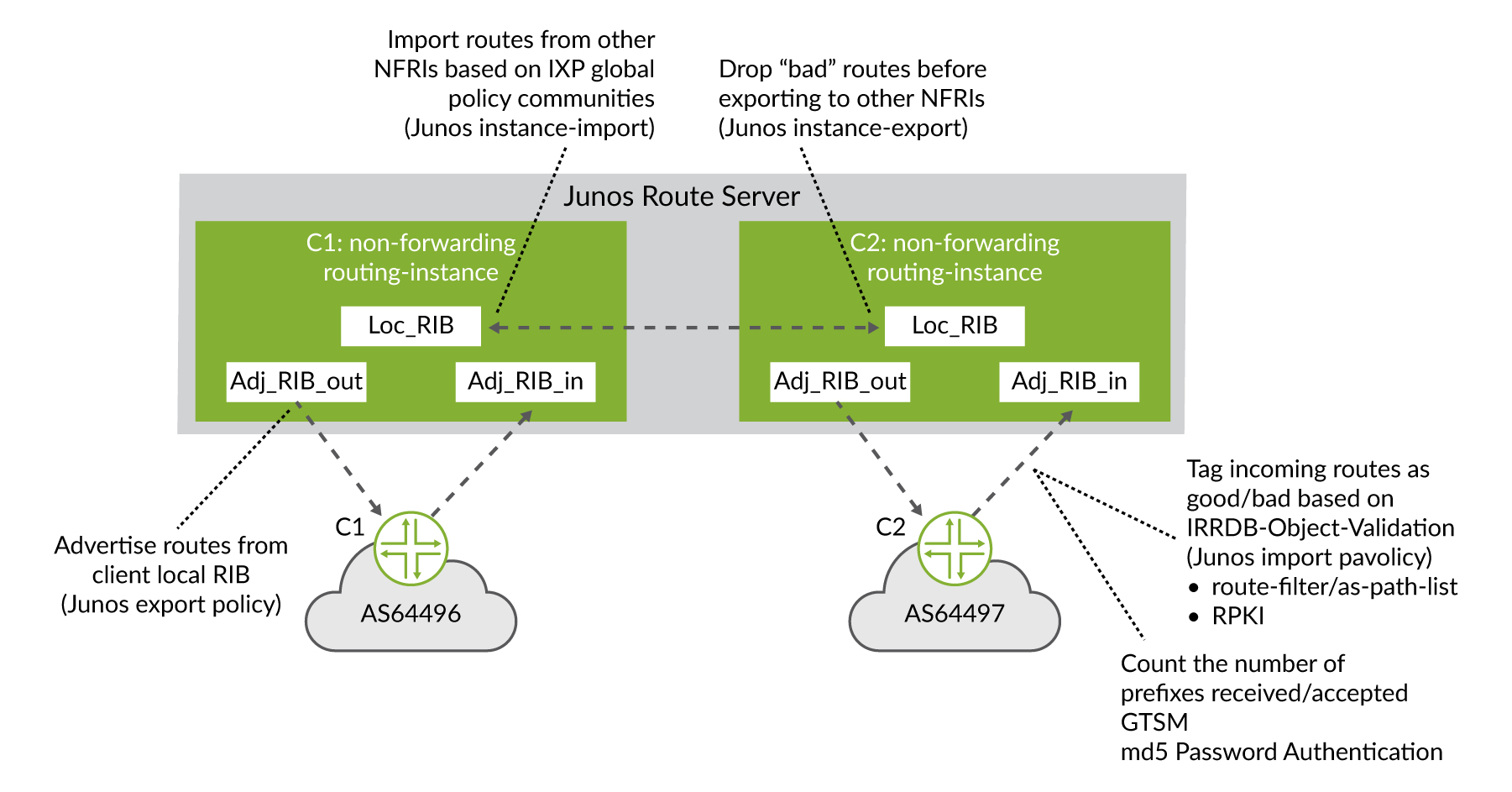
The databases described here are not to be confused with the routing table as these are only the tables used by the BGP process and never by the router for packet forwarding. Only the set of routes that exist in the Local-RIB are installed in the routing table based on a criterion specified by the local BGP speaker (depending on vendor implementation and preference of routing protocols).