Using a cRPD-based Route Server
This chapter covers some special configuration considerations for using a cRPD instance or instances as a route server.
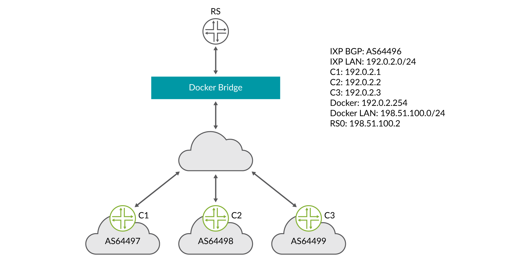
For the example below we will use the following attributes:
Docker bridge IP subnet is 198.51.100.0/24
IXP LAN subnet is 192.0.2.0/24
The router-server has been assigned the IP address of 192.0.2.254 on the IXP LAN
IXP BGP AS is 100
Special considerations for this deployment example:
Since the EBGP clients are on a different IP subnet than the IXP LAN, the EBGP sessions must be multi-hop. This is due to the fact that the container runs on the Docker bridge subnet.
You don’t configure interfaces when using cRPD. The interface address is read from the Docker container.
Example of route-server local address:
root@rs0> show interfaces routing
Interface	  State       Addresses
eth0.0        Up      MPLS enabled
                      ISO  enabled
                      INET 198.51.100.2
lo.0          Up      MPLS enabled
                      ISO  enabled
                      INET 127.0.0.1
Example of cRPD route-server configuration:
IXP client-router configuration:
It should be noted that this example doesn’t cover everything that should be configured on a client router peering with an operational route server in a live network. A good example of what should be configured on a client device running Junos OS taking part in IXP operations can be found here: https://www.ams-ix.net/ams/documentation/config-guide.
Synchronization of the Data and Control Plane
A challenging problem with IXP LANs is that the route servers are not active in the data plane between IXP member clients, so it’s possible for the data plane between clients to be DOWN while the EBGP sessions with the route server remain UP. As you can imagine, this would create a blackhole – Layer 3 thinks the destination is reachable and so the client is sending traffic while Layer 2 “circuit” is down.
Work is being done in the IETF to solve this problem with BFD (https://datatracker.ietf.org/doc/draft-ietf-idr-rs-bfd/).
The abstract of the aforementioned draft states:
When BGP route servers are used, the data plane is not congruent with the control plane. Therefore, peers at an Internet exchange can lose data connectivity without the control plane being aware of it, and packets are lost. This document proposes the use of a newly defined BGP Subsequent Address Family Identifier (SAFI) both to allow the route server to request its clients use BFD to track data plane connectivity to their peers’ addresses, and for the clients to signal that connectivity state back to the route server.
As of the writing of this book, there are no generally available or interoperable implementations of this draft. An external application such as HealthBot can discover and mitigate this problem as an alternative to the native BGP extensions proposed in the IETF draft.
The HealthBot Solution
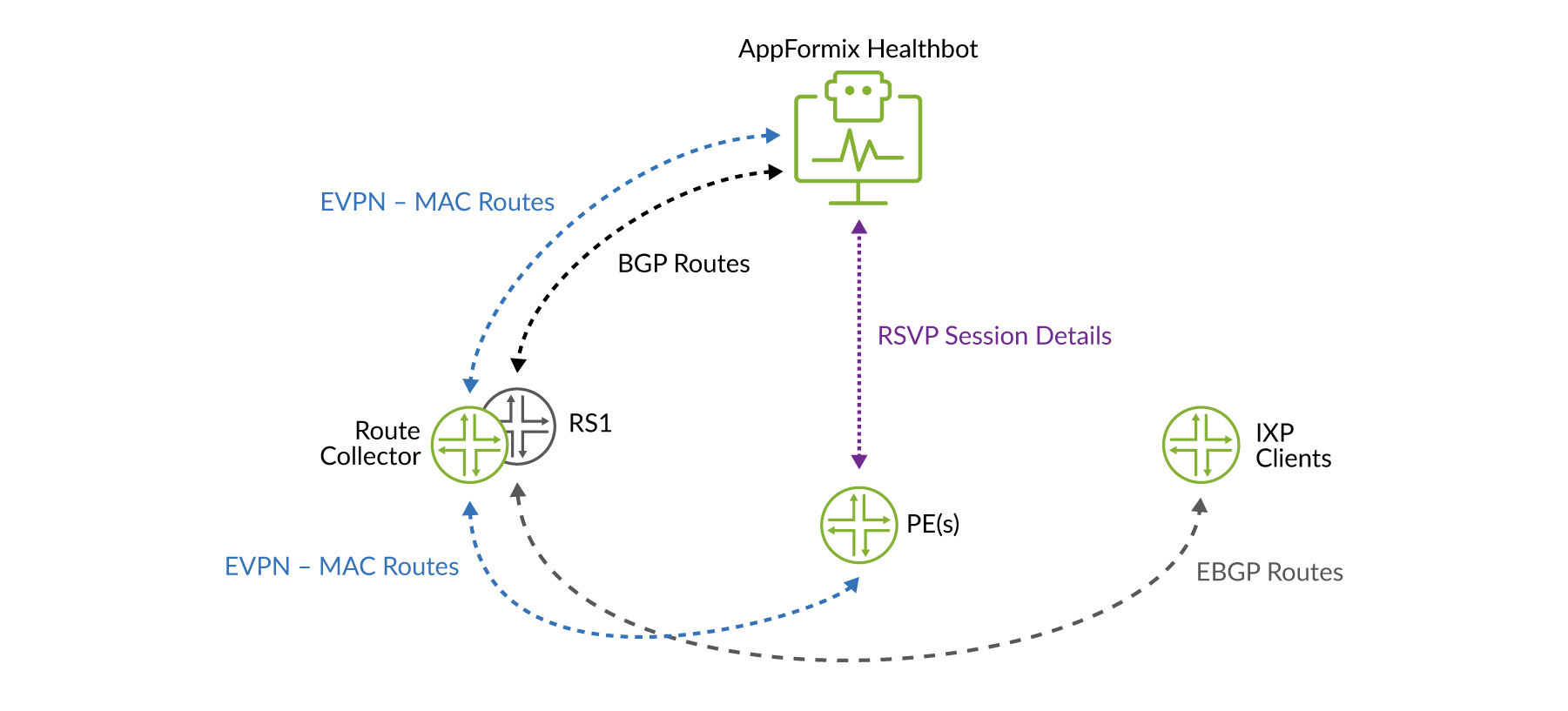
The HealthBot solution works first by correlating multiple pieces of data to detect the condition. HealthBot collects and/or receives the following data:
EBGP next hops from the route server
EVPN MAC routes from a route collector
Data plane OAM statistics between the PE routers
To correct the event, which is not straightforward, HealthBot does the following as illustrated in Figure 2:
Restricts route distribution only between route server clients that are impacted by modifying instance import policies accordingly.
Now let’s explore a working example; consider the sample topology in Figure 3.
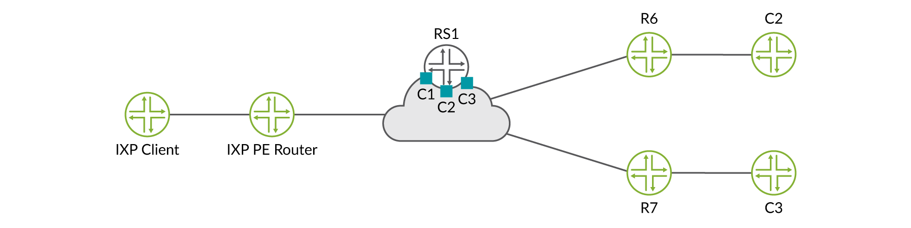
First HealthBot subscribes to the BGP telemetry sensor and collects data from the route server (vRR) and route collector. In this example, the route server is also acting as the route collector. Additionally, HealthBot subscribes to the MPLS iAgent sensor and collect label-switched path (LSP) statistics from the PE routers R1, R6, and R7.
Finding the routing-instance names for each routing server client CLI example:
regress@RS1> show route instance summary | match C
Instance	            Type
         Primary RIB	                    Active/holddown/hidden
C1	                  non-forwarding
         C1.inet.0	                       93/0/0
C2	                  non-forwarding
         C2.inet.0	                       62/0/0
C3	                  non-forwarding
         C3.inet.0	                       62/0/0
Finding the IXP client routers IP addresses (the BGP next hops) example:

Referring to Figure 4 to ensure the data plane is intact between PE routers, HealthBot monitors the status of RSVP-TE LSPs between all IXP PE routers:
regress@R6> show mpls lsp | match Up
Ingress LSP: 2 sessions
To              From            State RtP     ActivePath    LSPname
192.0.2.1         192.0.2.6         Up     0 *                    to-r1
192.0.2.2         192.0.2.6         Up     0 *                    to-r2

regress@R7> show mpls lsp | match Up
Ingress LSP: 2 sessions
To              From            State RtP     ActivePath    LSPname
192.0.2.1         192.0.2.7         Up     0 *                    to-r1
192.0.2.6         192.0.2.7         Up     0 *                    to-r6

regress@R1> show mpls lsp | match Up
Ingress LSP: 2 sessions
To              From            State RtP     ActivePath    LSPname
192.0.2.6         192.0.2.1         Up     0 *                    to-r6
192.0.2.7         192.0.2.1         Up     0 *                    to-r7
During normal operation, routes are exchanged between IXP members according to community-based output policies. Here we can see that C1 is receiving routes from both C2 (198.51.100.0/24), and C3 (203.0.113.0/24), respectively:
regress@C1> show route protocol bgp 198.51.100.1

inet.0: 96 destinations, 96 routes (95 active, 0 holddown, 1 hidden)
+ = Active Route, - = Last Active, * = Both

198.51.100.0/24	    *[BGP/170] 2d 23:20:23, localpref100, from 192.0.2.254
                     AS path: 2 I, validation-state: unverified
                    > to 192.0.2.2 via ge-0/0/1.0

regress@C1> show route protocol bgp 203.0.113.0

inet.0: 96 destinations, 96 routes (95 active, 0 holddown, 1 hidden)
+ = Active Route, - = Last Active, * = Both

203.0.113.0/24	    *[BGP/170] 3d 00:46:29, localpref100, from 192.0.2.254
                    AS path: 3 I, validation-state: unverified
                   > to 192.0.2.3 via ge-0/0/1.0
However, what if one of the RSVP-TE LSPs goes DOWN, for some reason, resulting in a broken data plane between R1 and R6, but the route server is still receiving routes from IXP members attached to those PE routers?

Down LSP ...
regress@R6# run show mpls lsp
Ingress LSP: 3 sessions
To              From            State RtP     ActivePath    LSPname
192.0.2.1         0.0.0.0           Dn     0       -              to-r1
192.0.2.7         192.0.2.6         Up     0 *                    to-r7
Total 3 displayed, Up 1, Down 2
But ...
regress@C1> show route protocol bgp 198.51.100.1

inet.0: 96 destinations, 96 routes (95 active, 0 holddown, 1 hidden)
+ = Active Route, - = Last Active, * = Both

198.51.100.0/24     *[BGP/170] 2d 23:20:23, localpref100, from 192.0.2.254
                     AS path: 2 I, validation-state: unverified
                   >  to 192.0.2.2 via ge-0/0/1.0

regress@C1> show route protocol bgp 203.0.113.0

inet.0: 96 destinations, 96 routes (95 active, 0 holddown, 1 hidden)
+ = Active Route, - = Last Active, * = Both

203.0.113.0/24	    *[BGP/170] 3d 00:46:29, localpref100, from 192.0.2.254
                     AS path: 3 I, validation-state: unverified
                   >  to 192.0.2.3 via ge-0/0/1.0
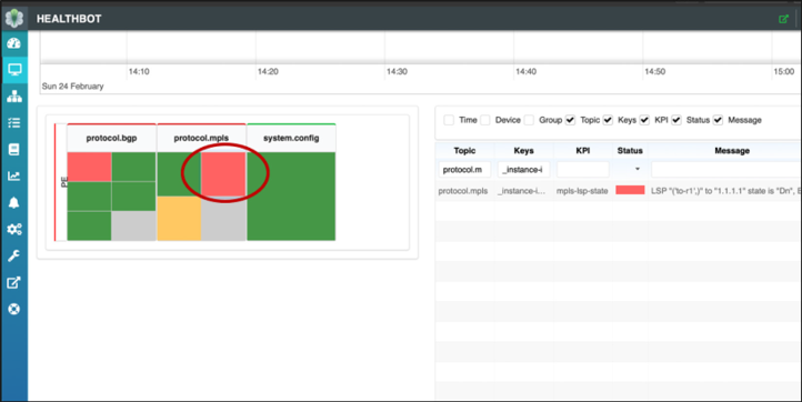
HealthBot will discover the situation, display a dashboard alarm, and modify the route server policy configuration to limit route distribution between impacted IXP member routers.
Modified route-server configuration:
Verification on IXP member router C1. As you can see, routes are no longer received from member C2:
regress@C1> show route protocol bgp 198.51.100.1

egress@C1> show route protocol bgp 203.0.113.0

iet.0: 68 destinations, 68 routes (67 active, 0 holddown, 1 hidden)
+ = Active Route, - = Last Active, * = Both

203.0.113.0/24	    *[BGP/170] 3d 01:10:07, localpref100, from 192.0.2.254
                     AS path: 3 I, validation-state: unverified
                   >  to 192.0.2.3 via ge-0/0/1.0
Once the data plane is restored, HealthBot will clear the alarm and revert the policy configuration.
A Dynamic and Automated Maximum Accepted Prefix Solution
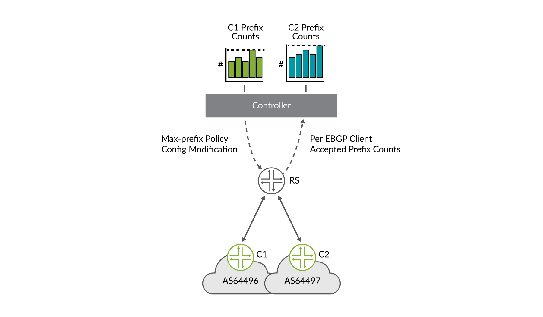
As was previously discussed in the security considerations section in Internet Exchange Point Overview chapter, determining, monitoring, and maintaining per route-server maximum-prefixes can be somewhat difficult for an IXP’s route-server deployment. Several solutions were presented, including various multiplication factors for determining the value. HealthBot offers another solution that involves ingesting real-time streaming telemetry from the route server, maintaining per route-server client accepted prefix counts, and dynamically modifying the route-server policy when vales change. This workflow for two route-server clients is depicted in Figure 7.
Let’s look at a real example. In the CLI output below you can see route server client C1. The route server is receiving and accepting 10 prefixes from client C1. You can also see that the route server is configured with a policy to accept a maximum of 15 prefixes from client C1:
root@rs> show bgp summary | match “Peer |C1.inet.0”
Peer      AS      InPkt     OutPkt     OutQ   Flaps Last Up/DwState|#Active/
Received/Accepted/Damped...
  C1.inet.0: 10/10/10/0
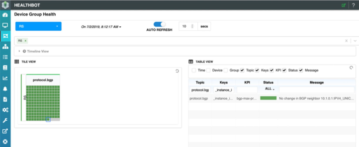
Also note the HealthBot dashboard; client C1 is selected in Figure 8 below and we can see that for the last statistics interval, there have been no changes to the maximum-prefix policy determined by HealthBot. This is indicated by both the ‘green’ status and the message in the table for that client. What is a statistics interval, you might ask? In this HealthBot solution we apply a very simple, user-defined interval over which to collect the number of accepted prefixes per route-server client. After each statistics interval, HealthBot takes the current value of accepted prefixes, multiplies by it by 1.5, also user configurable, and updates the route-server client policy with the new value.
Now, let’s have client C1 advertise a few more routes to the route server and add two more static routes to C1’s BGP export policy:
We can see that the additional prefixes are received and accepted by the route server in the output below:
root@rs> show bgp summary | match “Peer |C1.inet.0”
Peer                     AS      InPkt     OutPkt      OutQ   Flaps Last Up/Dwn State|#Active/
Received/Accepted/Damped...
r1001.inet.0: 12/12/12/0
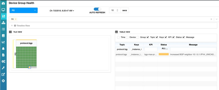
But look at the HealthBot dashboard now. The icon for client C1 has turned red. This is because the number of accepted prefixes has exceeded the threshold of 90%, also user configurable.

At the end of the statistics collection interval, we can also see that C1’s icon has now turned yellow, this indicates that HealthBot is changing the maximum-prefix policy for client C1 on the route server. And the HealthBot dashboard will again show C1’s icon as green since it is within policy and not exceeding any thresholds
As you can see, the route-server configuration has been updated with the new value (12 accepted prefix * 1.5) of 18:

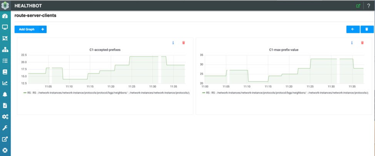
Lastly, each route-server client’s accepted prefixes and corresponding max-prefix value can be individually monitored. In Figure 12, you can see the number of accepted prefixes for client C1 along with the max-prefix policy value configured during the statistics interval.
Summary
The authors hope that the information provided in this book will help you get started designing, testing, and deploying Junos OS-based route servers. The configuration and design considerations discussed in this book are simply to get you started. In the end every IXP is unique and will have its own considerations for implementing policy.