Multinode High Availability
Learn about the Multinode High Availability solution and how you can use it in simple and reliable deployment models.
Business continuity is an important requirement of the modern network. Downtime of even a few seconds might cause disruption and inconvenience apart from affecting the OpEx and CapEx. Modern networks also have data centers spread across multiple geographical areas. In such scenarios, achieving high availability can be very challenging.
Juniper Networks® SRX Series Firewalls support a new solution, Multinode High Availability (MNHA), to address high availability requirements for modern data centers. In this solution, both the control plane and the data plane of the participating devices (nodes) are active at the same time. Thus, the solution provides interchassis resiliency.
The participating devices could be co-located or physically separated across geographical areas or other locations such as different rooms or buildings. Having nodes with high availability across geographical locations ensures resilient service. If a disaster affects one physical location, Multinode High Availability can fail over to a node in another physical location, thereby ensuring continuity.
- Benefits of Multinode High Availability
- Supported Features
- How Is Multinode High Availability Different from Chassis Cluster?
- Multinode High Availability Glossary
Benefits of Multinode High Availability
-
Reduced CapEx and OpEx—Eliminates the need for a switched network surrounding the firewall complex and the need for a direct Layer 2 (L2) connectivity between nodes
-
Network flexibility—Provides greater network flexibility by supporting high availability across Layer 3 (L3) and switched network segments.
-
Stateful resilient solution—Supports active control plane and data plane at the same time on both nodes.
-
Business continuity and disaster recovery—Maximizes availability, increasing redundancy within and across data centers and geographies.
-
Smooth upgrades—Supports different versions of Junos OS on two nodes to ensure smooth upgrades between the Junos OS releases, also allows to run two different version of Junos.
We support Multinode High Availability in active/backup mode and in active-active mode (with support of multiple services redundancy groups (SRGs). For the complete list of supported features and platforms, see Multinode High Availability in Feature Explorer.
Supported Features
MNHA infrastructure provides redundancy through two deployment models:
- Two-node MNHA: A pair of firewalls operating together for high availability.
- Four-node MNHA: Two pairs of firewalls distributed across domains for enhanced resilience.
SRX Series Firewalls with Multinode High Availability support the firewall and advanced security services—such as application security, Content Security, intrusion prevention system (IPS), firewall user authentication, NAT, ALG.
For the complete list of devices and features supported with Multinode High Availability, see Feature Explorer .
Multinode High Availability does not support transparent mode high availability (HA)
How Is Multinode High Availability Different from Chassis Cluster?
A chassis cluster operates in Layer 2 network environment and requires two links between the nodes (control link and fabric link). These links connect both nodes over dedicated VLANs using back-to-back cabling or over dark fiber. Control links and fabric links use dedicated physical ports on the SRX Series Firewall.
Multinode High Availability uses an encrypted logical interchassis link (ICL). The ICL connects the nodes over a routed path instead of a dedicated Layer 2 network. This routed path can use one or more revenue ports for best resiliency, it’s even possible to dedicate its own routing instance to these ports and paths to ensure total isolation which maximizes the resiliency of the solution.
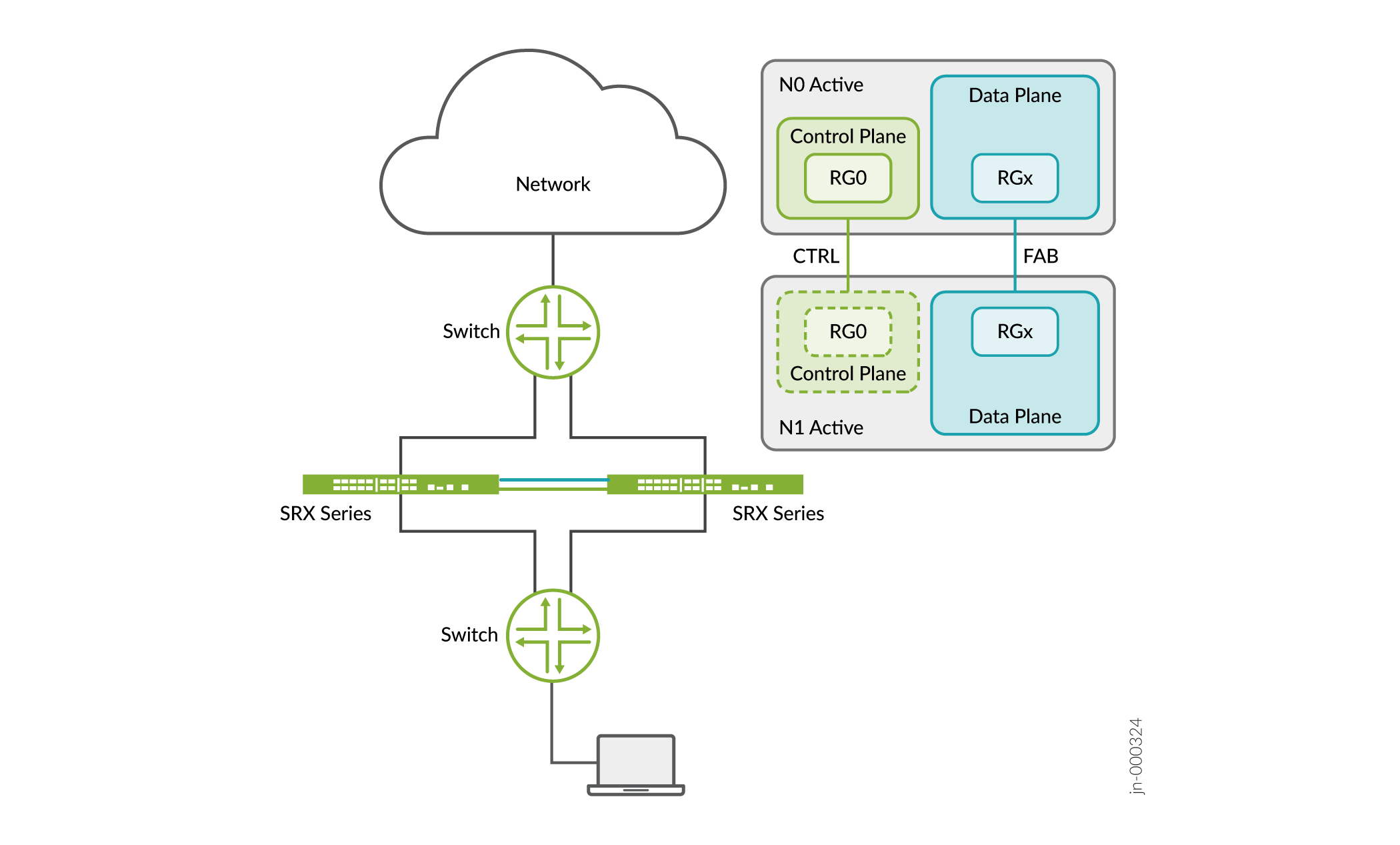
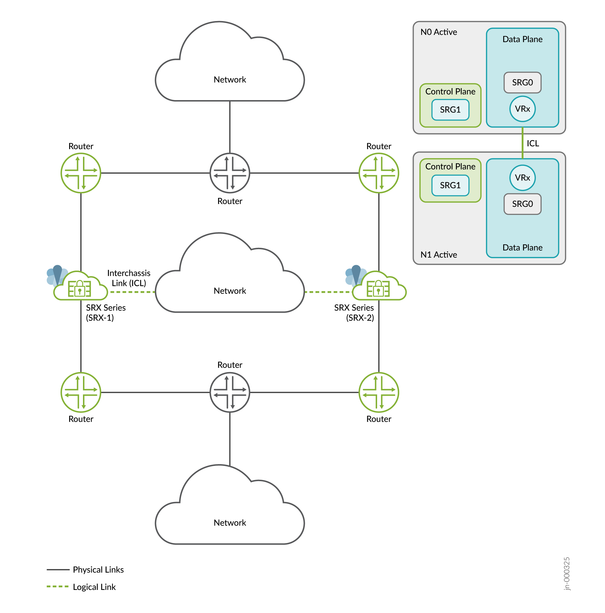
Table 1 lists the differences between the two architectures
| Parameters | Chassis Cluster | Multinode High Availability |
|---|---|---|
| Network topology | Nodes connect to a broadcast domain | Nodes connect to a router, a broadcast domain, or a combination of both.
|
| Network environment | Layer 2 |
|
| Traffic switchover approach | SRX Series Firewall sends GARP to the switch |
Switchover using IP path selection by a peer Layer 3 router or Layer 2 GARP from an SRX Series Firewall to a peer Layer 2 switch
|
| Public cloud | Not supported | Supported |
| Dynamic routing function | Routing process active on the SRX Series where the control plane (RG0) is active | Routing process active on each SRX Series Firewall participating in Multinode High Availability |
| Connection between SRX Series Firewalls |
|
Interchassis link (Layer 3 path) |
| Connectivity / Geo-redundance | Requires a dedicated Layer 2 stretch between the SRX Series nodes for the control link and fabric link. | Uses any routed path between the nodes for the Interchassis link. |
| IP monitoring to detect network failure |
|
|
Multinode High Availability Glossary
Let's begin by getting familiar with Multinode High Availability terms used in this documentation.
| Term | Description |
|---|---|
| active/active state (SRG0) | All security services/flows are inspected at each node and backed up on the other node. Security flows must be symmetric. |
| active/backup state (SRG1+) | SRG1+ remains active on one node at any given time and remains in backed up state on the other node. SRG1+ in the backup state is ready to take over traffic from the active SRG1 in case on a failure. |
| device priority |
Device priority (activeness‑priority) determines which node can act as the active node for a Service Redundancy Group (SRG) in an MNHA setup. A node with a higher numerical activeness‑priority value is selected as the active node for that SRG. If activeness‑priority is not explicitly configured for an SRG, the node with the higher node ID is preferred as the active node. |
| device preemption |
Device preemption allows a preferred node to resume as the active node after it recovers from a failure. The preferred node is determined either by a higher activeness‑priority value, (if configured), or by a higher node ID (when activeness‑priority is not configured). If you need to use a specific device to act as the active node, you must enable preemption on all participating devices and configure activeness‑priority values on each device. |
| failover | A failover happens when one node detects a failure (hardware/software and so on) and traffic transitions to the other node in a stateful manner. As result, the backup node in a high availability system takes over the task of the active node when the active node fails. |
| floating IP address or activeness probing IP address | An IP address that moves from an active node to the backup node during failover in a Multinode High Availability setup. This mechanism enables clients to communicate with the nodes using a single IP address. |
|
high availability/resiliency |
Ability of a system to eliminate single points of failure to ensure continuous operations over an extended period of time. |
| interchassis link | IP-based link (logical link) that connects nodes over a routed network in a
Multinode High Availability deployment. The ICL link is normally bound to the loopback
interfaces for most flexible deployments. Connectivity can be any routed or switched
path as long as the connectivity is reachable between the two IP addresses. The security device uses the ICL to synchronize and maintain state information and to handle device failover scenarios. |
| Interchassis link encryption | Link encryption provides data privacy for messages traversing over the network. As the ICL link transmits private data, it is important to encrypt the link. You must encrypt the ICL using IPsec VPN. |
| monitoring (BFD) | Monitoring of one or more links using Bidirectional Forwarding Detection (BFD). BFD monitoring triggers a routing path change or a system failover, depending on system configuration. |
| monitoring (IP) | Monitoring of a reliable IP address and system state in case of loss of communication with the peer node. |
| monitoring (path) | Method that uses ICMP to verify the reachability of the IP address. The default interval for ICMP ping probes is 1 second. |
| monitoring (system) | Monitoring of key hardware and software resources and infrastructures by triggering failover when a failure is detected on a node. |
| probing | Mechanism used to exchange messages between active and backup nodes in the high availability setup. The messages determine the status and health of the application on each individual node. |
| real-time object (RTO) | Special payload packet that contains the necessary information to synchronize the data from one node to the other node. |
| split-brain detection (also known as control plane detection or activeness conflict detection) | Event where the ICL between two Multinode High Availability nodes is down, and both nodes initiate an activeness determination probe (split-brain probe). Based on the response to the probe, subsequent failover to a new role is triggered |
| services redundancy group (SRG) | Failover unit that includes and manages a collection of objects on the participating nodes. The SRG on one node switches over to the other node when a failover is detected. |
| SRG0 | Default SRG for firewall and NAT services. The adjacent network determines which node processes traffic; this can be active/passive or active/active depending on the routing configuration. The firewall can influence which node(s) process traffic through routing attributes (routing preference, route cost, BGP, and so on). SRG0 manages services that need to hold state such as TCP handshake, Application Security, IDP, Content Security, Firewall, NAT, ALG, and so on. Servicing those on the active node is required to understand packet contents and some of these services are pass through (not terminating on the device except NAT, firewall authentication). SRG0 remains active on both nodes and forwards traffic from both the nodes to the active one that initiated the session analysis (if ICD link is setup). |
| SRG1+ | Inherently active/passive SRG for firewall, NAT, and VPN services; this group allows mapping one or more specific IP to the state of this group. In Switching or Hybrid mode (on Layer2 side), the VIP or VIPs are associated with this group and then sends gratuitous ARP to the local network. In Hybrid (Layer3 side) and routing modes, the prefix-list is associated with this group and made routable for the system (aptly in the specific routing-instance). SRX Series firewall can then use signal routes to attract traffic to the active node by manipulating routing policies (conditional routing is proposed method, based on signal routes representing the state of the SRG). Typically, an IPsec termination IP (this can be a loopback for example) can be announced on SRG1+ to terminate on the active node. When SRG1+ fails over, this IPsec IP will be now active on the other node, and announced via routing attributes. Runtime commands entered by the administrator influence which node processes traffic during normal operation. |
| synchronization | Process where controls and data plane states are synchronized across the nodes. |
| virtual IP (VIP) address | Virtual IP addresses in hybrid or default gateway mode are used for activeness determination and enforcement on the switching side in a Multinode High Availability setup. The virtual IP is controlled by the SRG1+. |
| virtual MAC (VMAC) address | (For hybrid and default gateway deployments). Virtual MAC address dynamically assigned to the interface on active node that faces the switching side. |
Now we are that familiar with Multinode High Availability features and terminology, let's proceed to understand how Multinode High Availability works.