Multicast on Layer 3 VPNs
You can configure multicast routing over a network running a Layer 3 VPN that complies with RFC 4364. This topic provides an overview of multicast and describes configuring devices to support multicast traffic in a Layer 3 VPN.
Understanding MVPN Concepts and Protocols
- Multicast over Layer 3 VPNs Overview
- Sending PIM Hello Messages to the PE Routers
- Sending PIM Join Messages to the PE Routers
- Receiving the Multicast Transmission
Multicast over Layer 3 VPNs Overview
In the unicast environment for Layer 3 VPNs, all VPN state information is contained within the PE routers. However, with multicast for Layer 3 VPNs, Protocol Independent Multicast (PIM) adjacencies are established in one of the following ways:
-
You can set PIM adjacencies between the CE router and the PE router through a VRF instance at the
[edit routing-instances instance-name protocols pim]hierarchy level. You must include thegroup-addressstatement for the provider tunnel, specifying a multicast group. The rendezvous point (RP) listed within the VRF-instance is the VPN customer RP (C-RP). -
You can also set the primary PIM instance and the PE’s IGP neighbors by configuring statements at the [edit protocols pim] hierarchy level. You must add the multicast group specified in the VRF instance to the primary PIM instance. The set of primary PIM adjacencies throughout the service provider network makes up the forwarding path that becomes an RP tree rooted at the service provider RP (SP-RP). Therefore, P routers within the provider core must maintain multicast state information for the VPNs.
For this to work properly, you need two types of RP routers for each VPN:
-
A C-RP—An RP router located somewhere within the VPN (can be either a service provider router or a customer router).
-
An SP-RP—An RP router located within the service provider network.
Note:A PE router can act as the SP-RP and the C-RP. Moving these multicast configuration tasks to service provider routers helps to simplify the multicast Layer 3 VPN configuration process for customers. However, configuration of both SP-RP and VPN C-RP on the same PE router is not supported.
To configure multicast over a Layer 3 VPN, you must install a Tunnel Services Physical Interface Card (PIC) on the following devices:
-
P routers acting as RPs
-
PE routers configured to run multicast routing
-
CE routers acting as designated routers or as VPN-RPs
For more information about running multicast over Layer 3 VPNs, see the following documents:
-
Internet draft draft-rosen-vpn-mcast-02.txt, Multicast in MPLS/BGP VPNs
The sections that follow describe the operation of a multicast VPN. Figure 1 illustrates the network topology used.
Sending PIM Hello Messages to the PE Routers
The first step in initializing multicast over a Layer 3 VPN is the distribution of a PIM Hello message from a PE router (called PE3 in this section) to all the other PE routers on which PIM is configured.
You configure PIM on the Layer 3 VPN routing instance on the PE3 router. If a Tunnel Services PIC is installed in the routing platform, a multicast interface is created. This interface is used to communicate between the PIM instance within the VRF routing instance and the primary PIM instance.
The following occurs when a PIM Hello message is sent to the PE routers:
-
A PIM Hello message is sent from the VRF routing instance over the multicast interface. A generic routing encapsulation (GRE) header is prepended to the PIM Hello message. The header message includes the VPN group address and the loopback address of the PE3 router.
-
A PIM register header is prepended to the Hello message as the packet is looped through the PIM encapsulation interface. This header contains the destination address of the SP-RP and the loopback address of the PE3 router.
-
The packet is sent to the SP-RP.
-
The SP-RP removes the top header from the packet and sends the remaining GRE-encapsulated Hello message to all the PE routers.
-
The primary PIM instance on each PE router handles the GRE encapsulated packet. Because the VPN group address is contained in the packet, the primary instance removes the GRE header from the packet and sends the Hello message, which contains the proper VPN group address within the VRF routing instance, over the multicast interface.
Sending PIM Join Messages to the PE Routers
To receive a multicast broadcast from a multicast network, a CE router must send a PIM Join message to the C-RP. The process described in this section refers to Figure 1.
The CE5 router needs to receive a multicast broadcast from multicast source 224.1.1.1. To receive the broadcast, it sends a PIM Join message to the C-RP (the PE3 router):
-
The PIM Join message is sent through the multicast interface, and a GRE header is prepended to the message. The GRE header contains the VPN group ID and the loopback address of the PE3 router.
-
The PIM Join message is then sent through the PIM encapsulation interface and a register header is prepended to the packet. The register header contains the IP address of the SP-RP and the loopback address of the PE3 router.
-
The PIM Join message is sent to the SP-RP by means of unicast routing.
-
On the SP-RP, the register header is stripped off (the GRE header remains) and the packet is sent to all the PE routers.
-
The PE2 router receives the packet, and because the link to the C-RP is through the PE2 router, it sends the packet through the multicast interface to remove the GRE header.
-
Finally, the PIM Join message is sent to the C-RP.
Receiving the Multicast Transmission
The steps that follow outline how a multicast transmission is propagated across the network:
-
The multicast source connected to the CE1 router sends the packet to group 224.1.1.1 (the VPN group address). The packet is encapsulated into a PIM register.
-
Because this packet already includes the PIM header, it is forwarded by means of unicast routing to the C-RP over the Layer 3 VPN.
-
The C-RP removes the packet and sends it out the downstream interfaces (which include the interface back to the CE3 router). The CE3 router also forwards this to the PE3 router.
-
The packet is sent through the multicast interface on the PE2 router; in the process, the GRE header is prepended to the packet.
-
Next, the packet is sent through the PIM encapsulation interface, where the register header is prepended to the data packet.
-
The packet is then forwarded to the SP-RP, which removes the register header, leaves the GRE header intact, and sends the packet to the PE routers.
-
PE routers remove the GRE header and forward the packet to the CE routers that requested the multicast broadcast by sending the PIM Join message.
Note:PE routers that have not received requests for multicast broadcasts from their connected CE routers still receive packets for the broadcast. These PE routers drop the packets as they are received.
Supported Multicast VPN Standards
Junos OS substantially supports the following RFCs and Internet draft, which define standards for multicast virtual private networks (VPNs).
RFC 6513, Multicast in MPLS/BGP IP VPNs
RFC 6514, BGP Encodings and Procedures for Multicast in MPLS/BGP IP VPNs
RFC 6515, IPv4 and IPv6 Infrastructure Addresses in BGP Updates for Multicast VPN
RFC 6625, Wildcards in Multicast VPN Auto-Discovery Routes
Internet draft draft-morin-l3vpn-mvpn-fast-failover-06.txt, Multicast VPN Fast Upstream Failover
Internet draft draft-raggarwa-l3vpn-bgp-mvpn-extranet-08.txt, Extranet in BGP Multicast VPN (MVPN)
-
RFC 7900, Extranet Multicast in BGP/IP MPLS VPNs (partial support)
-
RFC 8534, Explicit Tracking with Wildcard Routes in Multicast VPN (partial support)
-
RFC 9081, Interoperation between Multicast Virtual Private Network (MVPN) and Multicast Source Directory Protocol (MSDP) Source-Active Routes
See Also
Configuring Multicast Layer 3 VPNs
You can configure two types of multicast Layer 3 VPNs using the Junos OS:
Draft Rosen multicast VPNs—Draft Rosen multicast VPNs are described in RFC 4364, BGP/MPLS IP Virtual Private Networks (VPNs) and based on Section Two of the IETF Internet draft draft-rosen-vpn-mcast-06.txt, Multicast in MPLS/BGP VPNs (expired April 2004).
Next generation multicast VPNs—Next generation multicast VPNs are described in Internet drafts draft-ietf-l3vpn-2547bis-mcast-bgp-03.txt, BGP Encodings for Multicast in MPLS/BGP IP VPNs and draft-ietf-l3vpn-2547bis-mcast-02.txt, Multicast in MPLS/BGP IP VPNs.
This section describes how to configure draft Rosen multicast VPNs. This information is provided to you in case you already have dual PIM multicast VPNs configured on your network. For information about BGP MPLS multicast VPNs (also known as next generation multicast VPNs), see MBGP Multicast VPN Sites.
Draft-rosen multicast VPNs are not supported in a logical system environment even though the configuration statements can be configured under the logical-systems hierarchy.
You can configure a Layer 3 VPN to support multicast traffic using the Protocol Independent Multicast (PIM) routing protocol. To support multicast, you need to configure PIM on routers within the VPN and within the service provider’s network.
Each PE router configured to run multicast over Layer 3 VPNs must have a Tunnel Services PIC. A Tunnel Services PIC is also required on the P routers that act as rendezvous points (RPs). Tunnel Services PICs are also needed on all the CE routers acting as designated routers (first-hop/last-hop routers) or as RPs, just as they are in non-VPN PIM environments.
Configure the master PIM instance at the [edit protocols
pim] hierarchy level on the CE and PE routers. This master PIM
instance configuration on the PE router should match the configuration
on the service providers core routers.
You also need to configure a PIM instance for the Layer 3
VPN at the [edit routing-instances routing-instance-name protocols pim] hierarchy level on the PE router. This creates
a PIM instance for the indicated routing instance. The configuration
of the PIM instance on the PE router should match the PIM instance
configured on the CE router the PE router is connected to.
For information about how to configure PIM, see the Multicast Protocols User Guide .
Include the vpn-apply-export statement to configure
the group address designated for the VPN in the service provider’s
network. This address must be unique for each VPN and configured on
the VRF routing instance of all PE routers connecting to the same
VPN. It ensures that multicast traffic is transmitted only to the
specified VPN.
Include the vpn-apply-export statement:
vpn-apply-export address;
For a list of hierarchy levels at which you can configure this statement, see the statement summary section for this statement.
You can include this statement at the following hierarchy levels:
[edit routing-instances routing-instance-name protocols pim][edit logical-systems logical-system-name routing-instances routing-instance-name protocols pim]
The rest of the Layer 3 VPN configuration for multicast is conventional and is described in other sections of this manual. Most of the specific configuration tasks needed to activate multicast in a VPN environment involve PIM.
See Also
Example: Configuring PIM Join Load Balancing on Draft-Rosen Multicast VPN
This example shows how to configure multipath routing for external and internal virtual private network (VPN) routes with unequal interior gateway protocol (IGP) metrics, and Protocol Independent Multicast (PIM) join load balancing on provider edge (PE) routers running Draft-Rosen multicast VPN (MVPN). This feature allows customer PIM (C-PIM) join messages to be load-balanced across external and internal BGP (EIBGP) upstream paths when the PE router has both external BGP (EBGP) and internal BGP (IBGP) paths toward the source or rendezvous point (RP).
Requirements
This example requires the following hardware and software components:
Three MX Series routers.
Before you begin:
Configure the device interfaces.
Configure the following routing protocols on all PE routers:
OSPF
MPLS
LDP
PIM
BGP
Configure a multicast VPN.
Overview and Topology
Junos OS supports multipath configuration along with PIM join load balancing. This allows C-PIM join messages to be load-balanced across unequal EIBGP routes, if a PE router has EBGP and IBGP paths toward the source (or RP). In previous releases, only the active EBGP path was used to send the join messages. This feature is applicable to IPv4 C-PIM join messages.
During load balancing, if a PE router loses one or more EBGP paths toward the source (or RP), the C-PIM join messages that were previously using the EBGP path are moved to a multicast tunnel interface, and the reverse path forwarding (RPF) neighbor on the multicast tunnel interface is selected based on a hash mechanism.
On discovering the first EBGP path toward the source (or RP), only the new join messages get load-balanced across EIBGP paths, whereas the existing join messages on the multicast tunnel interface remain unaffected.
Though the primary goal for multipath PIM join load balancing is to utilize unequal EIBGP paths for multicast traffic, potential join loops can be avoided if a PE router chooses only the EBGP path when there are one or more join messages for different groups from a remote PE router. If the remote PE router’s join message arrives after the PE router has already chosen IBGP as the upstream path, then the potential loops can be broken by changing the selected upstream path to EBGP.
During a graceful Routing Engine switchover (GRES), the EIBGP path selection for C-PIM join messages can vary, because the upstream interface selection is performed again for the new Routing Engine based on the join messages it receives from the CE and PE neighbors. This can lead to disruption of multicast traffic depending on the number of join messages received and the load on the network at the time of the graceful restart. However, the nonstop active routing feature is not supported and has no impact on the multicast traffic in a Draft-Rosen MVPN scenario.
In this example, PE1 and PE2 are the upstream PE routers for which the multipath PIM join load-balancing feature is configured. Routers PE1 and PE2 have one EBGP path and one IBGP path each toward the source. The Source and Receiver attached to customer edge (CE) routers are Free BSD hosts.
On PE routers that have EIBGP paths toward the source (or RP), such as PE1 and PE2, PIM join load balancing is performed as follows:
The existing join-count-based load balancing is performed such that the algorithm first selects the least loaded C-PIM interface. If there is equal or no load on all the C-PIM interfaces, the join messages get distributed equally across the available upstream interfaces.
In Figure 2, if the PE1 router receives PIM join messages from the CE2 router, and if there is equal or no load on both the EBGP and IBGP paths toward the source, the join messages get load-balanced on the EIBGP paths.
If the selected least loaded interface is a multicast tunnel interface, then there can be a potential join loop if the downstream list of the customer join (C-join) message already contains the multicast tunnel interface. In such a case, the least loaded interface among EBGP paths is selected as the upstream interface for the C-join message.
Assuming that the IBGP path is the least loaded, the PE1 router sends the join messages to PE2 using the IBGP path. If PIM join messages from the PE3 router arrive on PE1, then the downstream list of the C-join messages for PE3 already contains a multicast tunnel interface, which can lead to a potential join loop, because both the upstream and downstream interfaces are multicast tunnel interfaces. In this case, PE1 uses only the EBGP path to send the join messages.
If the selected least loaded interface is a multicast tunnel interface and the multicast tunnel interface is not present in the downstream list of the C-join messages, the loop prevention mechanism is not necessary. If any PE router has already advertised data multicast distribution tree (MDT) type, length, and values (TLVs), that PE router is selected as the upstream neighbor.
When the PE1 router sends the join messages to PE2 using the least loaded IBGP path, and if PE3 sends its join messages to PE2, no join loop is created.
If no data MDT TLV corresponds to the C-join message, the least loaded neighbor on a multicast tunnel interface is selected as the upstream interface.
On PE routers that have only IBGP paths toward the source (or RP), such as PE3, PIM join load balancing is performed as follows:
The PE router only finds a multicast tunnel interface as the RPF interface, and load balancing is done across the C-PIM neighbors on a multicast tunnel interface.
Router PE3 load-balances PIM join messages received from the CE4 router across the IBGP paths to the PE1 and PE2 routers.
If any PE router has already advertised data MDT TLVs corresponding to the C-join messages, that PE router is selected as the RPF neighbor.
For a particular C-multicast flow, at least one of the PE routers having EIBGP paths toward the source (or RP) must use only the EBGP path to avoid or break join loops. As a result of the loop avoidance mechanism, a PE router is constrained to choose among EIBGP paths when a multicast tunnel interface is already present in the downstream list.
In Figure 2, assuming that the CE2 host is interested in receiving traffic from the Source and CE2 initiates multiple PIM join messages for different groups (Group 1 with group address 203.0.113.1, and Group 2 with group address 203.0.113.2), the join messages for both groups arrive on the PE1 router.
Router PE1 then equally distributes the join messages between the EIBGP paths toward the Source. Assuming that Group 1 join messages are sent to the CE1 router directly using the EBGP path, and Group 2 join messages are sent to the PE2 router using the IBGP path, PE1 and PE2 become the RPF neighbors for Group 1 and Group 2 join messages, respectively.
When the CE3 router initiates Group 1 and Group 2 PIM join messages, the join messages for both groups arrive on the PE2 router. Router PE2 then equally distributes the join messages between the EIBGP paths toward the Source. Since PE2 is the RPF neighbor for Group 2 join messages, it sends the Group 2 join messages directly to the CE1 router using the EBGP path. Group 1 join messages are sent to the PE1 router using the IBGP path.
However, if the CE4 router initiates multiple Group 1 and Group 2 PIM join messages, there is no control over how these join messages received on the PE3 router get distributed to reach the Source. The selection of the RPF neighbor by PE3 can affect PIM join load balancing on EIBGP paths.
If PE3 sends Group 1 join messages to PE1 and Group 2 join messages to PE2, there is no change in RPF neighbor. As a result, no join loops are created.
If PE3 sends Group 1 join messages to PE2 and Group 2 join messages to PE1, there is a change in the RPF neighbor for the different groups resulting in the creation of join loops. To avoid potential join loops, PE1 and PE2 do not consider IBGP paths to send the join messages received from the PE3 router. Instead, the join messages are sent directly to the CE1 router using only the EBGP path.
The loop avoidance mechanism in a Draft-Rosen MVPN has the following limitations:
Because the timing of arrival of join messages on remote PE routers determines the distribution of join messages, the distribution could be sub-optimal in terms of join count.
Because join loops cannot be avoided and can occur due to the timing of join messages, the subsequent RPF interface change leads to loss of multicast traffic. This can be avoided by implementing the PIM make-before-break feature.
The PIM make-before-break feature is an approach to detect and break C-PIM join loops in a Draft-Rosen MVPN. The C-PIM join messages are sent to the new RPF neighbor after establishing the PIM neighbor relationship, but before updating the related multicast forwarding entry. Though the upstream RPF neighbor would have updated its multicast forwarding entry and started sending the multicast traffic downstream, the downstream router does not forward the multicast traffic (because of RPF check failure) until the multicast forwarding entry is updated with the new RPF neighbor. This helps to ensure that the multicast traffic is available on the new path before switching the RPF interface of the multicast forwarding entry.
Configuration
CLI Quick Configuration
To quickly configure this example, copy the following commands, paste them into a text file, remove any line breaks, change any details necessary to match your network configuration, and then copy and paste the commands into the CLI at the [edit] hierarchy level.
PE1
set routing-instances vpn1 instance-type vrf set routing-instances vpn1 interface ge-5/0/4.0 set routing-instances vpn1 interface ge-5/2/0.0 set routing-instances vpn1 interface lo0.1 set routing-instances vpn1 route-distinguisher 1:1 set routing-instances vpn1 vrf-target target:1:1 set routing-instances vpn1 routing-options multipath vpn-unequal-cost equal-external-internal set routing-instances vpn1 protocols bgp export direct set routing-instances vpn1 protocols bgp group bgp type external set routing-instances vpn1 protocols bgp group bgp local-address 192.0.2.4 set routing-instances vpn1 protocols bgp group bgp family inet unicast set routing-instances vpn1 protocols bgp group bgp neighbor 192.0.2.5 peer-as 3 set routing-instances vpn1 protocols bgp group bgp1 type external set routing-instances vpn1 protocols bgp group bgp1 local-address 192.0.2.1 set routing-instances vpn1 protocols bgp group bgp1 family inet unicast set routing-instances vpn1 protocols bgp group bgp1 neighbor 192.0.2.2 peer-as 4 set routing-instances vpn1 protocols pim group-address 198.51.100.1 set routing-instances vpn1 protocols pim rp static address 10.255.8.168 set routing-instances vpn1 protocols pim interface all set routing-instances vpn1 protocols pim join-load-balance
PE2
set routing-instances vpn1 instance-type vrf set routing-instances vpn1 interface ge-2/0/3.0 set routing-instances vpn1 interface ge-4/0/5.0 set routing-instances vpn1 interface lo0.1 set routing-instances vpn1 route-distinguisher 2:2 set routing-instances vpn1 vrf-target target:1:1 set routing-instances vpn1 routing-options multipath vpn-unequal-cost equal-external-internal set routing-instances vpn1 protocols bgp export direct set routing-instances vpn1 protocols bgp group bgp1 type external set routing-instances vpn1 protocols bgp group bgp1 local-address 10.90.10.1 set routing-instances vpn1 protocols bgp group bgp1 family inet unicast set routing-instances vpn1 protocols bgp group bgp1 neighbor 10.90.10.2 peer-as 45 set routing-instances vpn1 protocols bgp group bgp type external set routing-instances vpn1 protocols bgp group bgp local-address 10.50.10.2 set routing-instances vpn1 protocols bgp group bgp family inet unicast set routing-instances vpn1 protocols bgp group bgp neighbor 10.50.10.1 peer-as 4 set routing-instances vpn1 protocols pim group-address 198.51.100.1 set routing-instances vpn1 protocols pim rp static address 10.255.8.168 set routing-instances vpn1 protocols pim interface all set routing-instances vpn1 protocols pim join-load-balance
Procedure
Step-by-Step Procedure
The following example requires you to navigate various levels in the configuration hierarchy. For information about navigating the CLI, see Using the CLI Editor in Configuration Mode. To configure the PE1 router:
Repeat this procedure for every Juniper Networks router in the MVPN domain, after modifying the appropriate interface names, addresses, and any other parameters for each router.
Configure a VPN routing and forwarding (VRF) instance.
[edit routing-instances vpn1] user@PE1# set instance-type vrf user@PE1# set interface ge-5/0/4.0 user@PE1# set interface ge-5/2/0.0 user@PE1# set interface lo0.1 user@PE1# set route-distinguisher 1:1 user@PE1# set vrf-target target:1:1Enable protocol-independent load balancing for the VRF instance.
[edit routing-instances vpn1] user@PE1# set routing-options multipath vpn-unequal-cost equal-external-internalConfigure BGP groups and neighbors to enable PE to CE routing.
[edit routing-instances vpn1 protocols] user@PE1# set bgp export direct user@PE1# set bgp group bgp type external user@PE1# set bgp group bgp local-address 192.0.2.4 user@PE1# set bgp group bgp family inet unicast user@PE1# set bgp group bgp neighbor 192.0.2.5 peer-as 3 user@PE1# set bgp group bgp1 type external user@PE1# set bgp group bgp1 local-address 192.0.2.1 user@PE1# set bgp group bgp1 family inet unicast user@PE1# set bgp group bgp1 neighbor 192.0.2.2 peer-as 4Configure PIM to enable PE to CE multicast routing.
[edit routing-instances vpn1 protocols] user@PE1# set pim group-address 198.51.100.1 user@PE1# set pim rp static address 10.255.8.168Enable PIM on all network interfaces.
[edit routing-instances vpn1 protocols] user@PE1# set pim interface allEnable PIM join load balancing for the VRF instance.
[edit routing-instances vpn1 protocols] user@PE1# set pim join-load-balance
Results
From configuration mode, confirm your configuration by entering the show routing-instances command. If the output does not display the intended configuration, repeat the instructions in this example to correct the configuration.
routing-instances {
vpn1 {
instance-type vrf;
interface ge-5/0/4.0;
interface ge-5/2/0.0;
interface lo0.1;
route-distinguisher 1:1;
vrf-target target:1:1;
routing-options {
multipath {
vpn-unequal-cost equal-external-internal;
}
}
protocols {
bgp {
export direct;
group bgp {
type external;
local-address 192.0.2.4;
family inet {
unicast;
}
neighbor 192.0.2.5 {
peer-as 3;
}
}
group bgp1 {
type external;
local-address 192.0.2.1;
family inet {
unicast;
}
neighbor 192.0.2.2 {
peer-as 4;
}
}
}
pim {
group-address 198.51.100.1;
rp {
static {
address 10.255.8.168;
}
}
interface all;
join-load-balance;
}
}
}
}
If you are done configuring the device, enter commit from configuration mode.
Verification
Confirm that the configuration is working properly.
Verifying PIM Join Load Balancing for Different Groups of Join Messages
Purpose
Verify PIM join load balancing for the different groups of join messages received on the PE1 router.
Action
From operational mode, run the show pim join instance extensive command.
user@PE1>show pim join instance extensive
Instance: PIM.vpn1 Family: INET
R = Rendezvous Point Tree, S = Sparse, W = Wildcard
Group: 203.0.113.1
Source: *
RP: 10.255.8.168
Flags: sparse,rptree,wildcard
Upstream interface: ge-5/2/0.1
Upstream neighbor: 10.10.10.2
Upstream state: Join to RP
Downstream neighbors:
Interface: ge-5/0/4.0
10.40.10.2 State: Join Flags: SRW Timeout: 207
Group: 203.0.113.2
Source: *
RP: 10.255.8.168
Flags: sparse,rptree,wildcard
Upstream interface: mt-5/0/10.32768
Upstream neighbor: 19.19.19.19
Upstream state: Join to RP
Downstream neighbors:
Interface: ge-5/0/4.0
10.40.10.2 State: Join Flags: SRW Timeout: 207
Group: 203.0.113.3
Source: *
RP: 10.255.8.168
Flags: sparse,rptree,wildcard
Upstream interface: ge-5/2/0.1
Upstream neighbor: 10.10.10.2
Upstream state: Join to RP
Downstream neighbors:
Interface: ge-5/0/4.0
10.40.10.2 State: Join Flags: SRW Timeout: 207
Group: 203.0.113.4
Source: *
RP: 10.255.8.168
Flags: sparse,rptree,wildcard
Upstream interface: mt-5/0/10.32768
Upstream neighbor: 19.19.19.19
Upstream state: Join to RP
Downstream neighbors:
Interface: ge-5/0/4.0
10.40.10.2 State: Join Flags: SRW Timeout: 207
Meaning
The output shows how the PE1 router has load-balanced the C-PIM join messages for four different groups.
For Group 1 (group address: 203.0.113.1) and Group 3 (group address: 203.0.113.3) join messages, the PE1 router has selected the EBGP path toward the CE1 router to send the join messages.
For Group 2 (group address: 203.0.113.2) and Group 4 (group address: 203.0.113.4) join messages, the PE1 router has selected the IBGP path toward the PE2 router to send the join messages.
MBGP Multicast VPN Sites
The main characteristics of MBGP MVPNs are:
They extend Layer 3 VPN service (RFC 4364) to support IP multicast for Layer 3 VPN service providers.
They follow the same architecture as specified by RFC 4364 for unicast VPNs. Specifically, BGP is used as the provider edge (PE) router-to-PE router control plane for multicast VPN.
They eliminate the requirement for the virtual router (VR) model (as specified in Internet draft draft-rosen-vpn-mcast, Multicast in MPLS/BGP VPNs) for multicast VPNs and the RFC 4364 model for unicast VPNs.
They rely on RFC 4364-based unicast with extensions for intra-AS and inter-AS communication.
An MBGP MVPN defines two types of site sets, a sender site set and a receiver site set. These sites have the following properties:
Hosts within the sender site set can originate multicast traffic for receivers in the receiver site set.
Receivers outside the receiver site set should not be able to receive this traffic.
Hosts within the receiver site set can receive multicast traffic originated by any host in the sender site set.
Hosts within the receiver site set should not be able to receive multicast traffic originated by any host that is not in the sender site set.
A site can be in both the sender site set and the receiver site set, so hosts within such a site can both originate and receive multicast traffic. For example, the sender site set could be the same as the receiver site set, in which case all sites could both originate and receive multicast traffic from one another.
Sites within a given MBGP MVPN might be within the same organization or in different organizations, which means that an MBGP MVPN can be either an intranet or an extranet. A given site can be in more than one MBGP MVPN, so MBGP MVPNs might overlap. Not all sites of a given MBGP MVPN have to be connected to the same service provider, meaning that an MBGP MVPN can span multiple service providers.
Feature parity for the MVPN extranet functionality or overlapping MVPNs on the Junos Trio chipset is supported in Junos OS Releases 11.1R2, 11.2R2, and 11.4.
Another way to look at an MBGP MVPN is to say that an MBGP MVPN is defined by a set of administrative policies. These policies determine both the sender site set and the receiver site set. These policies are established by MBGP MVPN customers, but implemented by service providers using the existing BGP and MPLS VPN infrastructure.
See Also
Example: Configuring MBGP Multicast VPNs
This example provides a step-by-step procedure to configure multicast services across a multiprotocol BGP (MBGP) Layer 3 virtual private network. (also referred to as next-generation Layer 3 multicast VPNs)
Requirements
This example uses the following hardware and software components:
Junos OS Release 9.2 or later
Five M Series, T Series, TX Series, or MX Series Juniper routers
One host system capable of sending multicast traffic and supporting the Internet Group Management Protocol (IGMP)
One host system capable of receiving multicast traffic and supporting IGMP
Depending on the devices you are using, you might be required to configure static routes to:
The multicast sender
The Fast Ethernet interface to which the sender is connected on the multicast receiver
The multicast receiver
The Fast Ethernet interface to which the receiver is connected on the multicast sender
Overview and Topology
This example shows how to configure the following technologies:
IPv4
BGP
OSPF
RSVP
MPLS
PIM sparse mode
Static RP
Topology
The topology of the network is shown in Figure 3.
Configuration
In any configuration session, it is a good practice to
periodically verify that the configuration can be committed using
the commit check command.
In this example, the router being configured is identified using the following command prompts:
CE1identifies the customer edge 1 (CE1) routerPE1identifies the provider edge 1 (PE1) routerPidentifies the provider core (P) routerCE2identifies the customer edge 2 (CE2) routerPE2identifies the provider edge 2 (PE2) router
To configure MBGP multicast VPNs for the network shown in Figure 3, perform the following steps:
- Configuring Interfaces
- Configuring OSPF
- Configuring BGP
- Configuring RSVP
- Configuring MPLS
- Configuring the VRF Routing Instance
- Configuring PIM
- Configuring the Provider Tunnel
- Configuring the Rendezvous Point
- Results
Configuring Interfaces
Step-by-Step Procedure
The following example requires you to navigate various levels in the configuration hierarchy. For information about navigating the CLI, see Using the CLI Editor in Configuration Mode in the CLI User Guide.
On each router, configure an IP address on the loopback logical interface 0 (
lo0.0).[edit interfaces] user@CE1# set lo0 unit 0 family inet address 192.168.6.1/32 primary user@PE1# set lo0 unit 0 family inet address 192.168.7.1/32 primary user@P# set lo0 unit 0 family inet address 192.168.8.1/32 primary user@PE2# set lo0 unit 0 family inet address 192.168.9.1/32 primary user@CE2# set lo0 unit 0 family inet address 192.168.0.1/32 primary
Use the
show interfaces tersecommand to verify that the IP address is correct on the loopback logical interface.On the PE and CE routers, configure the IP address and protocol family on the Fast Ethernet interfaces. Specify the
inetprotocol family type.[edit interfaces] user@CE1# set fe-1/3/0 unit 0 family inet address 10.10.12.1/24 user@CE1# set fe-0/1/0 unit 0 family inet address 10.0.67.13/30 [edit interfaces] user@PE1# set fe-0/1/0 unit 0 family inet address 10.0.67.14/30 [edit interfaces] user@PE2# set fe-0/1/0 unit 0 family inet address 10.0.90.13/30 [edit interfaces] user@CE2# set fe-0/1/0 unit 0 family inet address 10.0.90.14/30 user@CE2# set fe-1/3/0 unit 0 family inet address 10.10.11.1/24
Use the
show interfaces tersecommand to verify that the IP address is correct on the Fast Ethernet interfaces.On the PE and P routers, configure the ATM interfaces' VPI and maximum virtual circuits. If the default PIC type is different on directly connected ATM interfaces, configure the PIC type to be the same. Configure the logical interface VCI, protocol family, local IP address, and destination IP address.
[edit interfaces] user@PE1# set at-0/2/0 atm-options pic-type atm1 user@PE1# set at-0/2/0 atm-options vpi 0 maximum-vcs 256 user@PE1# set at-0/2/0 unit 0 vci 0.128 user@PE1# set at-0/2/0 unit 0 family inet address 10.0.78.5/32 destination 10.0.78.6 [edit interfaces] user@P# set at-0/2/0 atm-options pic-type atm1 user@P# set at-0/2/0 atm-options vpi 0 maximum-vcs 256 user@P# set at-0/2/0 unit 0 vci 0.128 user@P# set at-0/2/0 unit 0 family inet address 10.0.78.6/32 destination 10.0.78.5 user@P# set at-0/2/1 atm-options pic-type atm1 user@P# set at-0/2/1 atm-options vpi 0 maximum-vcs 256 user@P# set at-0/2/1 unit 0 vci 0.128 user@P# set at-0/2/1 unit 0 family inet address 10.0.89.5/32 destination 10.0.89.6 [edit interfaces] user@PE2# set at-0/2/1 atm-options pic-type atm1 user@PE2# set at-0/2/1 atm-options vpi 0 maximum-vcs 256 user@PE2# set at-0/2/1 unit 0 vci 0.128 user@PE2# set at-0/2/1 unit 0 family inet address 10.0.89.6/32 destination 10.0.89.5
Use the
show configuration interfacescommand to verify that the ATM interfaces' VPI and maximum VCs are correct and that the logical interface VCI, protocol family, local IP address, and destination IP address are correct.
Configuring OSPF
Step-by-Step Procedure
On the P and PE routers, configure the provider instance of OSPF. Specify the
lo0.0and ATM core-facing logical interfaces. The provider instance of OSPF on the PE router forms adjacencies with the OSPF neighbors on the other PE router and Router P.user@PE1# set protocols ospf area 0.0.0.0 interface at-0/2/0.0 user@PE1# set protocols ospf area 0.0.0.0 interface lo0.0 user@P# set protocols ospf area 0.0.0.0 interface lo0.0 user@P# set protocols ospf area 0.0.0.0 interface all user@P# set protocols ospf area 0.0.0.0 interface fxp0 disable user@PE2# set protocols ospf area 0.0.0.0 interface lo0.0 user@PE2# set protocols ospf area 0.0.0.0 interface at-0/2/1.0
Use the
show ospf interfacescommand to verify that thelo0.0and ATM core-facing logical interfaces are configured for OSPF.On the CE routers, configure the customer instance of OSPF. Specify the loopback and Fast Ethernet logical interfaces. The customer instance of OSPF on the CE routers form adjacencies with the neighbors within the VPN routing instance of OSPF on the PE routers.
user@CE1# set protocols ospf area 0.0.0.0 interface fe-0/1/0.0 user@CE1# set protocols ospf area 0.0.0.0 interface fe-1/3/0.0 user@CE1# set protocols ospf area 0.0.0.0 interface lo0.0 user@CE2# set protocols ospf area 0.0.0.0 interface fe-0/1/0.0 user@CE2# set protocols ospf area 0.0.0.0 interface fe-1/3/0.0 user@CE2# set protocols ospf area 0.0.0.0 interface lo0.0
Use the
show ospf interfacescommand to verify that the correct loopback and Fast Ethernet logical interfaces have been added to the OSPF protocol.On the P and PE routers, configure OSPF traffic engineering support for the provider instance of OSPF.
The
shortcutsstatement enables the master instance of OSPF to use a label-switched path as the next hop.user@PE1# set protocols ospf traffic-engineering shortcuts user@P# set protocols ospf traffic-engineering shortcuts user@PE2# set protocols ospf traffic-engineering shortcuts
Use the
show ospf overvieworshow configuration protocols ospfcommand to verify that traffic engineering support is enabled.
Configuring BGP
Step-by-Step Procedure
On Router P, configure BGP for the VPN. The local address is the local
lo0.0address. The neighbor addresses are the PE routers'lo0.0addresses.The
unicaststatement enables the router to use BGP to advertise network layer reachability information (NLRI). Thesignalingstatement enables the router to use BGP as the signaling protocol for the VPN.user@P# set protocols bgp group group-mvpn type internal user@P# set protocols bgp group group-mvpn local-address 192.168.8.1 user@P# set protocols bgp group group-mvpn family inet unicast user@P# set protocols bgp group group-mvpn family inet-mvpn signaling user@P# set protocols bgp group group-mvpn neighbor 192.168.9.1 user@P# set protocols bgp group group-mvpn neighbor 192.168.7.1
Use the
show configuration protocols bgpcommand to verify that the router has been configured to use BGP to advertise NLRI.On the PE and P routers, configure the BGP local autonomous system number.
user@PE1# set routing-options autonomous-system 0.65010 user@P# set routing-options autonomous-system 0.65010 user@PE2# set routing-options autonomous-system 0.65010
Use the
show configuration routing-optionscommand to verify that the BGP local autonomous system number is correct.On the PE routers, configure BGP for the VPN. Configure the local address as the local
lo0.0address. The neighbor addresses are thelo0.0addresses of Router P and the other PE router, PE2.user@PE1# set protocols bgp group group-mvpn type internal user@PE1# set protocols bgp group group-mvpn local-address 192.168.7.1 user@PE1# set protocols bgp group group-mvpn family inet-vpn unicast user@PE1# set protocols bgp group group-mvpn family inet-mvpn signaling user@PE1# set protocols bgp group group-mvpn neighbor 192.168.9.1 user@PE1# set protocols bgp group group-mvpn neighbor 192.168.8.1 user@PE2# set protocols bgp group group-mvpn type internal user@PE2# set protocols bgp group group-mvpn local-address 192.168.9.1 user@PE2# set protocols bgp group group-mvpn family inet-vpn unicast user@PE2# set protocols bgp group group-mvpn family inet-mvpn signaling user@PE2# set protocols bgp group group-mvpn neighbor 192.168.7.1 user@PE2# set protocols bgp group group-mvpn neighbor 192.168.8.1
Use the
show bgp groupcommand to verify that the BGP configuration is correct.On the PE routers, configure a policy to export the BGP routes into OSPF.
user@PE1# set policy-options policy-statement bgp-to-ospf from protocol bgp user@PE1# set policy-options policy-statement bgp-to-ospf then accept user@PE2# set policy-options policy-statement bgp-to-ospf from protocol bgp user@PE2# set policy-options policy-statement bgp-to-ospf then accept
Use the
show policy bgp-to-ospfcommand to verify that the policy is correct.
Configuring RSVP
Step-by-Step Procedure
On the PE routers, enable RSVP on the interfaces that participate in the LSP. Configure the Fast Ethernet and ATM logical interfaces.
user@PE1# set protocols rsvp interface fe-0/1/0.0 user@PE1# set protocols rsvp interface at-0/2/0.0 user@PE2# set protocols rsvp interface fe-0/1/0.0 user@PE2# set protocols rsvp interface at-0/2/1.0
On Router P, enable RSVP on the interfaces that participate in the LSP. Configure the ATM logical interfaces.
user@P# set protocols rsvp interface at-0/2/0.0 user@P# set protocols rsvp interface at-0/2/1.0
Use the
show configuration protocols rsvpcommand to verify that the RSVP configuration is correct.
Configuring MPLS
Step-by-Step Procedure
On the PE routers, configure an MPLS LSP to the PE router that is the LSP egress point. Specify the IP address of the
lo0.0interface on the router at the other end of the LSP. Configure MPLS on the ATM, Fast Ethernet, andlo0.0interfaces.To help identify each LSP when troubleshooting, configure a different LSP name on each PE router. In this example, we use the name
to-pe2as the name for the LSP configured on PE1 andto-pe1as the name for the LSP configured on PE2.user@PE1# set protocols mpls label-switched-path to-pe2 to 192.168.9.1 user@PE1# set protocols mpls interface fe-0/1/0.0 user@PE1# set protocols mpls interface at-0/2/0.0 user@PE1# set protocols mpls interface lo0.0 user@PE2# set protocols mpls label-switched-path to-pe1 to 192.168.7.1 user@PE2# set protocols mpls interface fe-0/1/0.0 user@PE2# set protocols mpls interface at-0/2/1.0 user@PE2# set protocols mpls interface lo0.0
Use the
show configuration protocols mplsandshow route label-switched-path to-pe1commands to verify that the MPLS and LSP configuration is correct.After the configuration is committed, use the
show mpls lsp name to-pe1andshow mpls lsp name to-pe2commands to verify that the LSP is operational.On Router P, enable MPLS. Specify the ATM interfaces connected to the PE routers.
user@P# set protocols mpls interface at-0/2/0.0 user@P# set protocols mpls interface at-0/2/1.0
Use the
show mpls interfacecommand to verify that MPLS is enabled on the ATM interfaces.On the PE and P routers, configure the protocol family on the ATM interfaces associated with the LSP. Specify the
mplsprotocol family type.user@PE1# set interfaces at-0/2/0 unit 0 family mpls user@P# set interfaces at-0/2/0 unit 0 family mpls user@P# set interfaces at-0/2/1 unit 0 family mpls user@PE2# set interfaces at-0/2/1 unit 0 family mpls
Use the
show mpls interfacecommand to verify that the MPLS protocol family is enabled on the ATM interfaces associated with the LSP.
Configuring the VRF Routing Instance
Step-by-Step Procedure
On the PE routers, configure a routing instance for the VPN and specify the
vrfinstance type. Add the Fast Ethernet andlo0.1customer-facing interfaces. Configure the VPN instance of OSPF and include the BGP-to-OSPF export policy.user@PE1# set routing-instances vpn-a instance-type vrf user@PE1# set routing-instances vpn-a interface lo0.1 user@PE1# set routing-instances vpn-a interface fe-0/1/0.0 user@PE1# set routing-instances vpn-a protocols ospf export bgp-to-ospf user@PE1# set routing-instances vpn-a protocols ospf area 0.0.0.0 interface all user@PE2# set routing-instances vpn-a instance-type vrf user@PE2# set routing-instances vpn-a interface lo0.1 user@PE2# set routing-instances vpn-a interface fe-0/1/0.0 user@PE2# set routing-instances vpn-a protocols ospf export bgp-to-ospf user@PE2# set routing-instances vpn-a protocols ospf area 0.0.0.0 interface all
Use the
show configuration routing-instances vpn-acommand to verify that the routing instance configuration is correct.On the PE routers, configure a route distinguisher for the routing instance. A route distinguisher allows the router to distinguish between two identical IP prefixes used as VPN routes. Configure a different route distinguisher on each PE router. This example uses 65010:1 on PE1 and 65010:2 on PE2.
user@PE1# set routing-instances vpn-a route-distinguisher 65010:1 user@PE2# set routing-instances vpn-a route-distinguisher 65010:2
Use the
show configuration routing-instances vpn-acommand to verify that the route distinguisher is correct.On the PE routers, configure default VRF import and export policies. Based on this configuration, BGP automatically generates local routes corresponding to the route target referenced in the VRF import policies. This example uses 2:1 as the route target.
Note:You must configure the same route target on each PE router for a given VPN routing instance.
user@PE1# set routing-instances vpn-a vrf-target target:2:1 user@PE2# set routing-instances vpn-a vrf-target target:2:1
Use the
show configuration routing-instances vpn-acommand to verify that the route target is correct.On the PE routers, configure the VPN routing instance for multicast support.
user@PE1# set routing-instances vpn-a protocols mvpn user@PE2# set routing-instances vpn-a protocols mvpn
Use the
show configuration routing-instance vpn-acommand to verify that the VPN routing instance has been configured for multicast support.On the PE routers, configure an IP address on loopback logical interface 1 (
lo0.1) used in the customer routing instance VPN.user@PE1# set interfaces lo0 unit 1 family inet address 10.10.47.101/32 user@PE2# set interfaces lo0 unit 1 family inet address 10.10.47.100/32
Use the
show interfaces tersecommand to verify that the IP address on the loopback interface is correct.
Configuring PIM
Step-by-Step Procedure
On the PE routers, enable PIM. Configure the
lo0.1and the customer-facing Fast Ethernet interface. Specify the mode assparseand the version as2.user@PE1# set routing-instances vpn-a protocols pim interface lo0.1 mode sparse user@PE1# set routing-instances vpn-a protocols pim interface lo0.1 version 2 user@PE1# set routing-instances vpn-a protocols pim interface fe-0/1/0.0 mode sparse user@PE1# set routing-instances vpn-a protocols pim interface fe-0/1/0.0 version 2 user@PE2# set routing-instances vpn-a protocols pim interface lo0.1 mode sparse user@PE2# set routing-instances vpn-a protocols pim interface lo0.1 version 2 user@PE2# set routing-instances vpn-a protocols pim interface fe-0/1/0.0 mode sparse user@PE2# set routing-instances vpn-a protocols pim interface fe-0/1/0.0 version 2
Use the
show pim interfaces instance vpn-acommand to verify that PIM sparse-mode is enabled on thelo0.1interface and the customer-facing Fast Ethernet interface.On the CE routers, enable PIM. In this example, we configure all interfaces. Specify the mode as
sparseand the version as2.user@CE1# set protocols pim interface all user@CE2# set protocols pim interface all mode sparse user@CE2# set protocols pim interface all version 2
Use the
show pim interfacescommand to verify that PIM sparse mode is enabled on all interfaces.
Configuring the Provider Tunnel
Step-by-Step Procedure
On Router PE1, configure the provider tunnel. Specify the multicast address to be used.
The
provider-tunnelstatement instructs the router to send multicast traffic across a tunnel.user@PE1# set routing-instances vpn-a provider-tunnel rsvp-te label-switched-path-template default-template
Use the
show configuration routing-instance vpn-acommand to verify that the provider tunnel is configured to use the default LSP template.On Router PE2, configure the provider tunnel. Specify the multicast address to be used.
user@PE2# set routing-instances vpn-a provider-tunnel rsvp-te label-switched-path-template default-template
Use the
show configuration routing-instance vpn-acommand to verify that the provider tunnel is configured to use the default LSP template.
Configuring the Rendezvous Point
Step-by-Step Procedure
Configure Router PE1 to be the rendezvous point. Specify the
lo0.1address of Router PE1. Specify the multicast address to be used.user@PE1# set routing-instances vpn-a protocols pim rp local address 10.10.47.101 user@PE1# set routing-instances vpn-a protocols pim rp local group-ranges 224.1.1.1/32
Use the
show pim rps instance vpn-acommand to verify that the correct local IP address is configured for the RP.On Router PE2, configure the static rendezvous point. Specify the
lo0.1address of Router PE1.user@PE2# set routing-instances vpn-a protocols pim rp static address 10.10.47.101
Use the
show pim rps instance vpn-acommand to verify that the correct static IP address is configured for the RP.On the CE routers, configure the static rendezvous point. Specify the
lo0.1address of Router PE1.user@CE1# set protocols pim rp static address 10.10.47.101 version 2 user@CE2# set protocols pim rp static address 10.10.47.101 version 2
Use the
show pim rpscommand to verify that the correct static IP address is configured for the RP.Use the
commit checkcommand to verify that the configuration can be successfully committed. If the configuration passes the check, commit the configuration.Start the multicast sender device connected to CE1.
Start the multicast receiver device connected to CE2.
Verify that the receiver is receiving the multicast stream.
Use
showcommands to verify the routing, VPN, and multicast operation.
Results
The configuration and verification parts of this example have been completed. The following section is for your reference.
The relevant sample configuration for Router CE1 follows.
Router CE1
interfaces {
lo0 {
unit 0 {
family inet {
address 192.168.6.1/32 {
primary;
}
}
}
}
fe-0/1/0 {
unit 0 {
family inet {
address 10.0.67.13/30;
}
}
}
fe-1/3/0 {
unit 0 {
family inet {
address 10.10.12.1/24;
}
}
}
}
protocols {
ospf {
area 0.0.0.0 {
interface fe-0/1/0.0;
interface lo0.0;
interface fe-1/3/0.0;
}
}
pim {
rp {
static {
address 10.10.47.101 {
version 2;
}
}
}
interface all;
}
}
The relevant sample configuration for Router PE1 follows.
Router PE1
interfaces {
lo0 {
unit 0 {
family inet {
address 192.168.7.1/32 {
primary;
}
}
}
}
fe-0/1/0 {
unit 0 {
family inet {
address 10.0.67.14/30;
}
}
}
at-0/2/0 {
atm-options {
pic-type atm1;
vpi 0 {
maximum-vcs 256;
}
}
unit 0 {
vci 0.128;
family inet {
address 10.0.78.5/32 {
destination 10.0.78.6;
}
}
family mpls;
}
}
lo0 {
unit 1 {
family inet {
address 10.10.47.101/32;
}
}
}
}
routing-options {
autonomous-system 0.65010;
}
protocols {
rsvp {
interface fe-0/1/0.0;
interface at-0/2/0.0;
}
mpls {
label-switched-path to-pe2 {
to 192.168.9.1;
}
interface fe-0/1/0.0;
interface at-0/2/0.0;
interface lo0.0;
}
bgp {
group group-mvpn {
type internal;
local-address 192.168.7.1;
family inet-vpn {
unicast;
}
family inet-mvpn {
signaling;
}
neighbor 192.168.9.1;
neighbor 192.168.8.1;
}
}
ospf {
traffic-engineering {
shortcuts;
}
area 0.0.0.0 {
interface at-0/2/0.0;
interface lo0.0;
}
}
}
policy-options {
policy-statement bgp-to-ospf {
from protocol bgp;
then accept;
}
}
routing-instances {
vpn-a {
instance-type vrf;
interface lo0.1;
interface fe-0/1/0.0;
route-distinguisher 65010:1;
provider-tunnel {
rsvp-te {
label-switched-path-template {
default-template;
}
}
}
vrf-target target:2:1;
protocols {
ospf {
export bgp-to-ospf;
area 0.0.0.0 {
interface all;
}
}
pim {
rp {
local {
address 10.10.47.101;
group-ranges {
224.1.1.1/32;
}
}
}
interface lo0.1 {
mode sparse;
version 2;
}
interface fe-0/1/0.0 {
mode sparse;
version 2;
}
}
mvpn;
}
}
}
The relevant sample configuration for Router P follows.
Router P
interfaces {
lo0 {
unit 0 {
family inet {
address 192.168.8.1/32 {
primary;
}
}
}
}
at-0/2/0 {
atm-options {
pic-type atm1;
vpi 0 {
maximum-vcs 256;
}
}
unit 0 {
vci 0.128;
family inet {
address 10.0.78.6/32 {
destination 10.0.78.5;
}
}
family mpls;
}
}
at-0/2/1 {
atm-options {
pic-type atm1;
vpi 0 {
maximum-vcs 256;
}
}
unit 0 {
vci 0.128;
family inet {
address 10.0.89.5/32 {
destination 10.0.89.6;
}
}
family mpls;
}
}
}
routing-options {
autonomous-system 0.65010;
}
protocols {
rsvp {
interface at-0/2/0.0;
interface at-0/2/1.0;
}
mpls {
interface at-0/2/0.0;
interface at-0/2/1.0;
}
bgp {
group group-mvpn {
type internal;
local-address 192.168.8.1;
family inet {
unicast;
}
family inet-mvpn {
signaling;
}
neighbor 192.168.9.1;
neighbor 192.168.7.1;
}
}
ospf {
traffic-engineering {
shortcuts;
}
area 0.0.0.0 {
interface lo0.0;
interface all;
interface fxp0.0 {
disable;
}
}
}
}
The relevant sample configuration for Router PE2 follows.
Router PE2
interfaces {
lo0 {
unit 0 {
family inet {
address 192.168.9.1/32 {
primary;
}
}
}
}
fe-0/1/0 {
unit 0 {
family inet {
address 10.0.90.13/30;
}
}
}
at-0/2/1 {
atm-options {
pic-type atm1;
vpi 0 {
maximum-vcs 256;
}
}
unit 0 {
vci 0.128;
family inet {
address 10.0.89.6/32 {
destination 10.0.89.5;
}
}
family mpls;
}
}
lo0 {
unit 1 {
family inet {
address 10.10.47.100/32;
}
}
}
}
routing-options {
autonomous-system 0.65010;
}
protocols {
rsvp {
interface fe-0/1/0.0;
interface at-0/2/1.0;
}
mpls {
label-switched-path to-pe1 {
to 192.168.7.1;
}
interface lo0.0;
interface fe-0/1/0.0;
interface at-0/2/1.0;
}
bgp {
group group-mvpn {
type internal;
local-address 192.168.9.1;
family inet-vpn {
unicast;
}
family inet-mvpn {
signaling;
}
neighbor 192.168.7.1;
neighbor 192.168.8.1;
}
}
ospf {
traffic-engineering {
shortcuts;
}
area 0.0.0.0 {
interface lo0.0;
interface at-0/2/1.0;
}
}
}
policy-options {
policy-statement bgp-to-ospf {
from protocol bgp;
then accept;
}
}
routing-instances {
vpn-a {
instance-type vrf;
interface fe-0/1/0.0;
interface lo0.1;
route-distinguisher 65010:2;
provider-tunnel {
rsvp-te {
label-switched-path-template {
default-template;
}
}
}
vrf-target target:2:1;
protocols {
ospf {
export bgp-to-ospf;
area 0.0.0.0 {
interface all;
}
}
pim {
rp {
static {
address 10.10.47.101;
}
}
interface fe-0/1/0.0 {
mode sparse;
version 2;
}
interface lo0.1 {
mode sparse;
version 2;
}
}
mvpn;
}
}
}
The relevant sample configuration for Router CE2 follows.
Router CE2
interfaces {
lo0 {
unit 0 {
family inet {
address 192.168.0.1/32 {
primary;
}
}
}
}
fe-0/1/0 {
unit 0 {
family inet {
address 10.0.90.14/30;
}
}
}
fe-1/3/0 {
unit 0 {
family inet {
address 10.10.11.1/24;
}
family inet6 {
address fe80::205:85ff:fe88:ccdb/64;
}
}
}
}
protocols {
ospf {
area 0.0.0.0 {
interface fe-0/1/0.0;
interface lo0.0;
interface fe-1/3/0.0;
}
}
pim {
rp {
static {
address 10.10.47.101 {
version 2;
}
}
}
interface all {
mode sparse;
version 2;
}
}
}
Configuring Point-to-Multipoint LSPs for an MBGP MVPN
The Junos OS supports point-to-multipoint label-switched paths (LSPs) for MBGP MVPNs. Point-to-multipoint LSPs for multicast VPNs are supported for intra-autonomous system (AS) environments (within an AS), but are not supported for inter-AS environments (between autonomous systems). A point-to-multipoint LSP is an RSVP-signaled LSP with a single source and multiple destinations.
You can configure point-to-multipoint LSPs for MBGP MVPNs as follows:
Static point-to-multipoint LSPs—Configure static point-to-multipoint LSPs using the standard MPLS LSP statements specified at the
[edit protocols mpls]hierarchy level. You manually configure each of the leaf nodes for the point-to-multipoint LSP.Dynamic point-to-multipoint LSPs using the default template—Configuring dynamic point-to-multipoint LSPs using the
default-templateoption causes the leaf nodes to be discovered automatically. The leaf nodes are discovered through BGP intra-AS automatic discovery. Thedefault-templateoption allows you to minimize the amount of configuration needed. However, it does not allow you to configure any of the standard MPLS options.Dynamic point-to-multipoint LSPs using a user-configured template—Configuring dynamic point-to-multipoint LSPs using a user-configured template also causes the leaf nodes to be discovered automatically. By creating your own template for the point-to-multipoint LSPs, all of the standard MPLS features (such as bandwidth allocation and traffic engineering) can be configured.
Be aware of the following properties for the egress PE router in a point-to-multipoint LSP configured for a multicast VPN:
Penultimate hop-popping is not used by point-to-multipoint LSPs for multicast VPNs. Only ultimate hop-popping is used.
You must configure either the
vrf-table-labelstatement or a virtual loopback tunnel interface on the egress PE router.If you configure the
vrf-table-labelstatement on the egress PE router, and the egress PE router is also a transit router for the point-to-multipoint LSP, the penultimate hop router sends two copies of each packet over the link to the egress PE router.If you configure the
vrf-table-labelstatement on the egress PE router, and the egress PE router is not a transit router for the point-to-multipoint LSP, the penultimate hop router can send just one copy of each packet over the link to the egress PE router.If you configure a virtual loopback tunnel interface on the egress PE router, and the egress PE router is also a transit router for the point-to-multipoint LSP, the penultimate hop router sends just one copy of each packet over the link to the egress PE router. A virtual loopback tunnel interface can perform two lookups on an incoming packet, one for the multicast MPLS lookup and one for the IP lookup.
Junos OS Release 11.2 and earlier do not support point-to-multipoint LSPs with next-generation multicast VPNs on MX80 routers.
The following sections describe how to configure point-to-multipoint LSPs for MBGP MVPNs:
- Configuring RSVP-Signaled Inclusive Point-to-Multipoint LSPs for an MBGP MVPN
- Configuring Selective Provider Tunnels for an MBGP MVPN
Configuring RSVP-Signaled Inclusive Point-to-Multipoint LSPs for an MBGP MVPN
You can configure LDP-signaled or RSVP-signaled inclusive point-to-multipoint LSPs for MBGP MVPNs. Aggregation is not supported, so you need to configure an inclusive point-to-multipoint LSP for each sender PE router in each multicast VPN routing instance. The sender PE router is in the sender site set of the MBGP MVPN.
To configure a static RSVP-signaled inclusive point-to-multipoint
LSP, include the static-lsp statement:
static-lsp lsp-name;
You can include this statement at the following hierarchy levels:
[edit routing-instances routing-instance-name provider-tunnel rsvp-te][edit logical-systems logical-system-name routing-instances routing-instance-name provider-tunnel rsvp-te]
To configure dynamic inclusive point-to-multipoint LSPs, include
the label-switched-path-template statement:
label-switched-path-template (Multicast) { (default-template | lsp-template-name); }
You can include this statement at the following hierarchy levels:
[edit routing-instances routing-instance-name provider-tunnel rsvp-te][edit logical-systems logical-system-name routing-instances routing-instance-name provider-tunnel rsvp-te]
You can configure either the default-template option
or manually configure a point-to-multipoint LSP template and specify
the template name.
Configuring Selective Provider Tunnels for an MBGP MVPN
You can configure LDP-signaled or RSVP-signaled selective point-to-multipoint LSPs (also referred to as selective provider tunnels) for MBGP MVPNs. Selective point-to-multipoint LSPs send traffic only to the receivers configured for the multicast VPNs, helping to minimize flooding in the service provider's network.
As with inclusive point-to-multipoint LSPs, you can configure both dynamic and static selective tunnels for the multicast VPN.
To configure selective point-to-multipoint provider tunnels,
include the selective statement:
selective {
group multicast--prefix/prefix-length {
source ip--prefix/prefix-length {
ldp-p2mp;
pim-ssm {
group-range multicast-prefix;
}
rsvp-te {
label-switched-path-template {
(default-template | lsp-template-name);
}
static-lsp point-to-multipoint-lsp-name;
}
threshold-rate kbps;
}
wildcard-source {
ldp-p2mp;
pim-ssm {
group-range multicast-prefix;
}
rsvp-te {
label-switched-path-template {
(default-template | lsp-template-name);
}
static-lsp point-to-multipoint-lsp-name;
}
threshold-rate kbps;
}
}
tunnel-limit number;
wildcard-group-inet {
wildcard-source {
ldp-p2mp;
pim-ssm {
group-range multicast-prefix;
}
rsvp-te {
label-switched-path-template {
(default-template | lsp-template-name);
}
static-lsp lsp-name;
}
threshold-rate number;
}
}
wildcard-group-inet6 {
wildcard-source {
ldp-p2mp;
pim-ssm {
group-range multicast-prefix;
}
rsvp-te {
label-switched-path-template {
(default-template | lsp-template-name);
}
static-lsp lsp-name;
}
threshold-rate number;
}
}
}
You can include these statements at the following hierarchy levels:
[edit routing-instances routing-instance-name provider-tunnel][edit logical-systems logical-system-name routing-instances routing-instance-name provider-tunnel]
The following sections describe how to configure selective point-to-multipoint LSPs for MBGP MVPNs:
- Configuring the Multicast Group Address for an MBGP MVPN
- Configuring the Multicast Source Address for an MBGP MVPN
- Configuring Static Selective Point-to-Multipoint LSPs for an MBGP MVPN
- Configuring Dynamic Selective Point-to-Multipoint LSPs for an MBGP MVPN
- Configuring the Threshold for Dynamic Selective Point-to-Multipoint LSPs for an MBGP MVPN
- Configuring the Tunnel Limit for Dynamic Selective Point-to-Multipoint LSPs for an MBGP MVPN
Configuring the Multicast Group Address for an MBGP MVPN
To configure a point-to-multipoint LSP for an MBGP MVPN, you
need to specify a multicast group address by including the group statement:
group address { ... }
You can include this statements at the following hierarchy levels:
[edit routing-instances routing-instance-name provider-tunnel selective][edit logical-systems logical-system-name routing-instances routing-instance-name provider-tunnel selective]
The address must be a valid multicast group address. Multicast
uses the Class D IP address range (224.0.0.0 through 239.255.255.255).
Configuring the Multicast Source Address for an MBGP MVPN
To configure a point-to-multipoint LSP for an MBGP MVPN, specify
a multicast source address by including the source statement:
source address { ... }
You can include this statement at the following hierarchy levels:
[edit routing-instances routing-instance-name provider-tunnel selective group address][edit logical-systems logical-system-name routing-instances routing-instance-name provider-tunnel selective group address]
Configuring Static Selective Point-to-Multipoint LSPs for an MBGP MVPN
You can configure a static selective point-to-multipoint LSP
for an MBGP MVPN. You need to configure a static LSP using the standard
MPLS LSP statements at the [edit protocols mpls] hierarchy
level. You then include the static LSP in your selective point-to-multipoint
LSP configuration by using the static-lsp statement. Once
this functionality is enabled on the source PE router, the static
point-to-multipoint LSP is created based on your configuration.
To configure a static selective point-to-multipoint LSP, include
the rsvp-te and the static-lsp statements:
rsvp-te static-lsp lsp-name;
You can include these statements at the following hierarchy levels:
[edit routing-instances routing-instance-name provider-tunnel selective group address source source-address][edit logical-systems logical-system-name routing-instances routing-instance-name provider-tunnel selective group address source source-address]
Configuring Dynamic Selective Point-to-Multipoint LSPs for an MBGP MVPN
You can configure a dynamic selective point-to-multipoint LSP for an MBGP MVPN. The leaf nodes for a dynamic point-to-multipoint LSP can be automatically discovered using leaf automatic discovery routes. Selective provider multicast service interface (S-PMSI) automatic discovery routes are also supported.
To configure a dynamic selective point-to-multipoint provider
tunnel, include the rsvp-te and label-switched-path-template statements:
rsvp-te label-switched-path-template {
(default-template | lsp-template-name);
}
You can include these statements at the following hierarchy levels:
[edit routing-instances routing-instance-name provider-tunnel selective group address source source-address][edit logical-systems logical-system-name routing-instances routing-instance-name provider-tunnel selective group address source source-address]
The label-switched-path-template statement includes
the following options:
default-template—Specify that point-to-multipoint LSPs are generated dynamically based on the default template. No user configuration is required for the LSPs. However, the automatically generated LSPs include none of the common LSP features, such as bandwidth allocation and traffic engineering.lsp-template-name—Specify the name of an LSP template to be used for the point-to-multipoint LSP. You need to configure the LSP template to be used as a basis for the point-to-multipoint LSPs. You can configure any of the common LSP features for this template.
Configuring the Threshold for Dynamic Selective Point-to-Multipoint LSPs for an MBGP MVPN
To configure a selective point-to-multipoint LSP dynamically,
you need to specify the data threshold (in kilobits per second)
required before a new tunnel is created using the threshold-rate statement:
threshold-rate number;
You can include this statement at the following hierarchy levels:
[edit routing-instances routing-instance-name provider-tunnel selective group address source source-address][edit logical-systems logical-system-name routing-instances routing-instance-name provider-tunnel selective group address source source-address]
Configuring the Tunnel Limit for Dynamic Selective Point-to-Multipoint LSPs for an MBGP MVPN
To configure a limit on the number of tunnels that can be generated
for a dynamic point-to-multipoint LSP, include the tunnel-limit statement:
tunnel-limit number;
You can include this statement at the following hierarchy levels:
[edit routing-instances routing-instance-name provider-tunnel selective][edit logical-systems logical-system-name routing-instances routing-instance-name provider-tunnel selective]
See Also
Segmented Inter-Area Point-to-Multipoint Label-Switched Paths Overview
Junos OS supports point-to-multipoint (P2MP) label-switched paths (LSPs) for BGP MVPNs. BGP MVPN supports non-segmented intra-autonomous systems (ASs) and segmented inter-autonomous systems (ASs).
In order to connect PE routers that are in different areas but in the same AS and require P2MP connectivity, Junos OS allows you to segment the P2MP LSPs at the area boundary as described in Internet draft draft-ietf-mpls-seamless-mcast-14.txt. You can use non-segmented LSPs for low-rate multicast flows, and segmented LSPs for high-rate flows. A segmented P2MP LSP within an AS consists of the following segments:
Ingress area segment — The ingress area segment is rooted at a PE router or autonomous system boundary router (ASBR). The leaves of this segment are PEs, ASBRs, or area border routers (ABRs).
Backbone area segment — The backbone area segment is rooted at an ABR that is connected to the ingress area/ingress ABR.
Egress area segment — The egress area segment is rooted at an ABR in the egress area or egress ABR.
These areas can be IGP areas or areas based on BGP peer groups, where ABR can be a region border router (RBR). In either case, the transit ABRs/RBRs should be configured on the BGP route reflector (RR).
Each of the intra-area segments can be carried over provider tunnels such as P2MP RSVP-TE LSP, P2MP mLDP LSP, or ingress replication.
Segmentation of inter-area P2MP LSP occurs when the S-PMSI autodiscovery (AD) routes are advertised. This triggers the inclusion of a new BGP extended community or inter-area P2MP segmented next-hop extended community. The segmented inter-area P2MP LSP can be separated into the following three different roles:
Ingress PE or ASBR — Ingress PE router originates S-PMSI A-D routes. If inter-region segmentation is required, then the PE router generates the S-PMSI A-D routes carrying the inter-area P2MP segmented next-hop router (S-NH) community. The inter-region segmentation can be added for any selective tunnel. The segmentation can happen based on the threshold or fan-out attributes. If the threshold is configured for a selective tunnel, then MVPN starts migrating the flow to a segmented S-PMSI on reaching the threshold rate value. The threshold attribute applies to RSVP, LDP, and IR tunnels. You can trigger the segmentation based on the fan-out attribute, which is the number of leaves. Once the number of leaf A-D routes exceeds the fan-out value, the traffic flow is moved to segmented S-PMSI. The fan-out attribute for LDP tunnels is not applicable at the ingress PE router. If the S-PMSI with ingress replication has configured only the threshold, then the threshold is used to trigger the migration to segmented LSP. If fan-out is also set, then the migration is triggered when the traffic rate multiplied by the number of leaf A-D routes exceeds the threshold value. The segmented threshold and fan-out values are checked based on the existing data threshold checking interval, which by default is every 60 seconds. This prevents the flow from getting migrated too frequently.
Transit ABRs — When the transit ABR (either ingress ABR or egress ABR) receives an S-PMSI A-D route with the segmentation of inter-region configured, the ABR checks if the S-PMSI is carrying a S-NH extended community attribute. If the S-NH attribute is present in the incoming S-PMSI, then the ABR checks for the tunnel-type to be carried by the S-PMSI. The ABR then generates the tunnel-type across the backbone area or the egress area .
Note:An ABR can set a template to define the provider tunnel type in each region or BGP group. The tunnel type in each region can be incoming, ingress-replication, LDP-P2MP, or RSVP-TE.
If the tunnel type is incoming, then it indicates that the tunnel type across the ABR remains the same. If the tunnel type is different across the ABR, then the transit ABR modifies the S-PMSI tunnel attribute and the S-NH attribute to its router-id and re-advertises the route to its BGP peers. If no template is configured on the ABR then the ABR simply reflects the incoming S-PMSI routes without changing any of the attributes to its BGP peers.
Egress PE or ASBR — Egress PE routers or ASBRs learn the upstream node from the segmented next-hop extended community carried in the received S-PMSI A-D routes and responds with the leaf A-D routes carrying the upstream node IP address in the route target extended community (EC).
You can configure the BGP policy to accept or reject the S-PMSI A-D routes carrying the inter-area P2MP segmented next-hop community.
See Also
Configuring Segmented Inter-Area P2MP LSP
In order to connect PE routers that are in different areas but in the same AS and that require P2MP connectivity, Junos OS allows you to segment the P2MP LSPs at the area boundary as described in Internet draft draft-ietf-mpls-seamless-mcast-14.txt .
To configure segmented inter-area P2MP LSPs at the ingress area segment, the backbone area segment, and the egress area segment, you must do the following:
See Also
Example: Configuring Segmented Inter-Area P2MP LSP
This example shows how to segment the P2MP LSPs at the area boundary as described in Internet draft draft-ietf-mpls-seamless-mcast-14.txt. You can configure policies on the segmented next-hop extended community (S-NH EC) so that S-PMSI A-D routes with the S-NH EC is reflected by the ABR while all other routes are reflected by other route reflectors.
Requirements
This example uses the following hardware and software components:
-
Fourteen MX Series 5G Universal Routing Platforms
-
Junos OS Release 15.1 or later running on all the routers
Before you begin:
-
Configure the device interfaces.
-
Configure OSPF.
Overview
Starting with Junos OS Release 15.1, P2MP LSPs can be segmented at the area boundary. A segmented P2MP LSP consists of ingress area segment(Ingress PE router or ASBR), backbone area segment (Transit ABR), and egress area segment (Egress PE routers or ASBRs). Each of the intra-area segments can be carried over provider tunnels such as P2MP RSVP-TE LSP, P2MP mLDP LSP, or ingress replication. Segmentation of inter-area P2MP LSP occurs when the S-PMSI autodiscovery (AD) routes are advertised, which triggers the inclusion of a new BGP extended community or inter-area P2MP segmented next-hop extended community in the ingress PE router or ASBR, transit ABR, and egress PE routers or ASBRs.
To configure inter-region segmentation at the ingress PE router,
configure the inter-region-segmented statement at the [edit routing-instances instance-name provider-tunnel] hierarchy level. To configure the inter-region template at the transit
ABRs, configure the inter-region-template template-name
statement at the [edit protocols mvpn] hierarchy
level. To configure inter-region segmentation at the transit ABR,
configure the inter-region statement at the [edit
routing-instance instance-name provider-tunnel] hierarchy level.
Topology
In the topology shown in Figure 4, the segmented tunnel combination is as follows:
-
Ingress area tunnel — PE1 to ABR1 with IR as the tunnel.
-
Backbone area tunnel — ABR1, ABR2, and ABR3 with RSVP-TE as the tunnel.
-
Egress area tunnel — ABR2 to PE2 and PE4, ABR3 to PE3 with RSVP-TE as the tunnel.
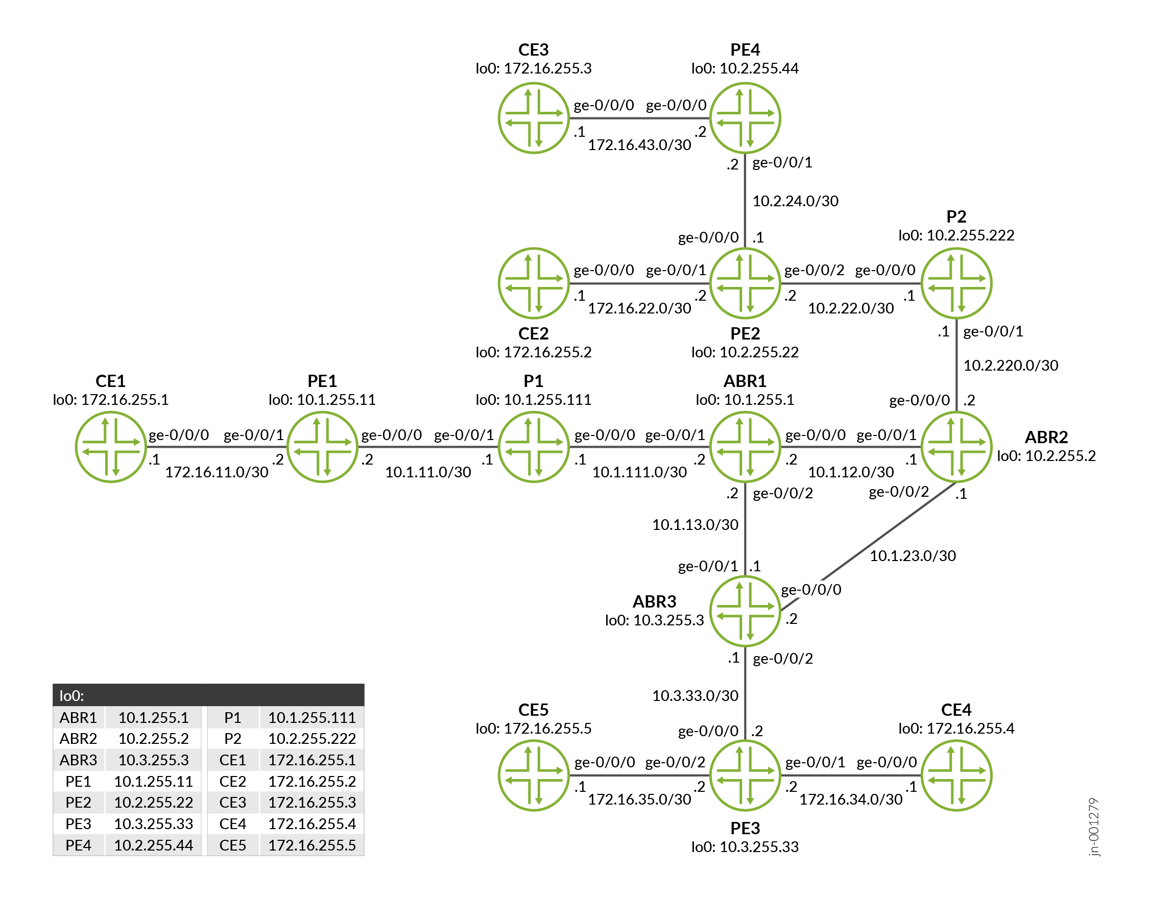
Configuration
CLI Quick Configuration
To quickly configure this example, copy the
following commands, paste them into a text file, remove any line breaks,
change any details necessary to match your network configuration,
copy and paste the commands into the CLI at the [edit] hierarchy
level, and then enter commit from configuration mode.
PE1
set chassis fpc 0 pic 0 tunnel-services bandwidth 1g set interfaces ge-0/0/0 unit 0 family inet address 10.1.11.2/30 set interfaces ge-0/0/0 unit 0 family mpls set interfaces ge-0/0/1 unit 0 family inet address 172.16.11.2/30 set interfaces ge-0/0/1 unit 0 family mpls set interfaces vt-0/0/10 unit 0 family inet set interfaces lo0 unit 0 family inet address 10.1.255.11/32 set interfaces lo0 unit 1 family inet address 10.1.255.101/32 set policy-options policy-statement bgp-to-ospf from protocol bgp set policy-options policy-statement bgp-to-ospf then accept set routing-instances vpn1 instance-type vrf set routing-instances vpn1 protocols mvpn mvpn-mode spt-only set routing-instances vpn1 protocols ospf area 0.0.0.1 interface all set routing-instances vpn1 protocols ospf area 0.0.0.1 interface lo0.1 set routing-instances vpn1 protocols ospf export bgp-to-ospf set routing-instances vpn1 protocols ospf3 area 0.0.0.1 interface all set routing-instances vpn1 protocols ospf3 export bgp-to-ospf set routing-instances vpn1 protocols pim rp local family inet address 10.1.255.101 set routing-instances vpn1 protocols pim interface all mode sparse-dense set routing-instances vpn1 interface ge-0/0/1.0 set routing-instances vpn1 interface vt-0/0/10.0 multicast set routing-instances vpn1 interface lo0.1 set routing-instances vpn1 route-distinguisher 10.1.255.11:100 set routing-instances vpn1 vrf-target target:123:1 set routing-instances vpn1 vrf-table-label set routing-instances vpn1 provider-tunnel selective group 224.1.1.1/32 source 172.16.11.1/32 ingress-replication label-switched-path set routing-instances vpn1 provider-tunnel selective group 224.1.1.1/32 source 172.16.11.1/32 threshold-rate 10 set routing-instances vpn1 provider-tunnel selective group 224.1.1.1/32 source 172.16.11.1/32 inter-region-segmented threshold 0 set routing-instances vpn1 provider-tunnel family inet ingress-replication label-switched-path set routing-options router-id 10.1.255.11 set routing-options autonomous-system 65550 set protocols bgp group IBGP type internal set protocols bgp group IBGP local-address 10.1.255.11 set protocols bgp group IBGP family inet any set protocols bgp group IBGP family inet-vpn unicast set protocols bgp group IBGP family inet-vpn multicast set protocols bgp group IBGP family inet-mvpn signaling set protocols bgp group IBGP neighbor 10.1.255.1 set protocols ldp interface all set protocols ldp interface fxp0.0 disable set protocols ldp p2mp set protocols mpls ipv6-tunneling set protocols mpls interface fxp0.0 disable set protocols mpls interface ge-0/0/0.0 set protocols mpls interface lo0.0 set protocols ospf traffic-engineering set protocols ospf area 0.0.0.1 interface fxp0.0 disable set protocols ospf area 0.0.0.1 interface ge-0/0/0.0 set protocols ospf area 0.0.0.1 interface lo0.0 set protocols pim interface all set protocols pim interface fxp0.0 disable set protocols pim interface lo0.0 set protocols pim default-vpn-source interface-name lo0.0 set protocols rsvp interface fxp0.0 disable set protocols rsvp interface ge-0/0/0.0 set protocols rsvp interface lo0.0
CE1
set interfaces ge-0/0/0 unit 0 family inet address 172.16.11.1/30 set interfaces lo0 unit 0 family inet address 172.16.255.1/32 set routing-options router-id 172.16.255.1 set protocols ospf area 0.0.0.1 interface all set protocols ospf area 0.0.0.1 interface fxp0.0 disable set protocols pim rp static address 10.1.255.101 set protocols pim interface all mode sparse-dense set protocols pim interface fxp0.0 disable set protocols pim interface ge-0/0/0.0 set protocols pim interface lo0.0
P1
set interfaces ge-0/0/0 unit 0 family inet address 10.1.111.1/30 set interfaces ge-0/0/0 unit 0 family mpls set interfaces ge-0/0/1 unit 0 family inet address 10.1.11.1/30 set interfaces ge-0/0/1 unit 0 family mpls set interfaces lo0 unit 0 family inet address 10.1.255.111/32 set routing-options router-id 10.1.255.111 set protocols ldp interface all set protocols ldp interface fxp0.0 disable set protocols ldp p2mp set protocols mpls ipv6-tunneling set protocols mpls interface fxp0.0 disable set protocols mpls interface all set protocols ospf traffic-engineering set protocols ospf area 0.0.0.1 interface fxp0.0 disable set protocols ospf area 0.0.0.1 interface all set protocols pim interface all set protocols pim interface fxp0.0 disable set protocols pim interface lo0.0 set protocols rsvp interface fxp0.0 disable set protocols rsvp interface all set protocols rsvp interface lo0.0
ABR1
set interfaces ge-0/0/0 unit 0 family inet address 10.1.12.2/30 set interfaces ge-0/0/0 unit 0 family mpls set interfaces ge-0/0/1 unit 0 family inet address 10.1.111.2/30 set interfaces ge-0/0/1 unit 0 family mpls set interfaces ge-0/0/2 unit 0 family inet address 10.1.13.2/30 set interfaces ge-0/0/2 unit 0 family mpls set interfaces lo0 unit 0 family inet address 10.1.255.1/32 set routing-instances vpn1 instance-type vrf set routing-instances vpn1 route-distinguisher 10.1.255.1:100 set routing-instances vpn1 vrf-target target:123:1 set routing-instances vpn1 vrf-table-label set routing-instances vpn1 provider-tunnel inter-region template template_1 set routing-options router-id 10.1.255.1 set routing-options autonomous-system 65550 set protocols bgp group IBGP_1 type internal set protocols bgp group IBGP_1 local-address 10.1.255.1 set protocols bgp group IBGP_1 family inet any set protocols bgp group IBGP_1 family inet-vpn unicast set protocols bgp group IBGP_1 family inet-vpn multicast set protocols bgp group IBGP_1 family inet-mvpn signaling set protocols bgp group IBGP_1 cluster 0.0.0.1 set protocols bgp group IBGP_1 neighbor 10.1.255.11 set protocols bgp group IBGP_0 type internal set protocols bgp group IBGP_0 local-address 10.1.255.1 set protocols bgp group IBGP_0 family inet any set protocols bgp group IBGP_0 family inet-vpn unicast set protocols bgp group IBGP_0 family inet-vpn multicast set protocols bgp group IBGP_0 family inet-mvpn signaling set protocols bgp group IBGP_0 neighbor 10.2.255.2 set protocols bgp group IBGP_0 neighbor 10.3.255.3 set protocols ldp interface all set protocols ldp p2mp set protocols mpls ipv6-tunneling set protocols mpls interface fxp0.0 disable set protocols mpls interface all set protocols mvpn inter-region-template template template_1 region IBGP_0 rsvp-te label-switched-path-template default-template set protocols mvpn inter-region-template template template_2 region IBGP_0 ldp-p2mp set protocols mvpn inter-region-template template template_3 region IBGP_0 ingress-replication create-new-ucast-tunnel set protocols mvpn inter-region-template template template_3 region IBGP_0 ingress-replication label-switched-path label-switched-path-template default-template set protocols mvpn inter-region-template template template_4 all-regions incoming set protocols mvpn inter-region-template template template_5 region IBGP_0 rsvp-te static-lsp ABR1_to_ABR3 set protocols ospf traffic-engineering set protocols ospf area 0.0.0.1 interface fxp0.0 disable set protocols ospf area 0.0.0.1 interface ge-0/0/1.0 set protocols ospf area 0.0.0.0 interface ge-0/0/0.0 set protocols ospf area 0.0.0.0 interface ge-0/0/2.0 set protocols ospf area 0.0.0.0 interface lo0.0 set protocols pim interface all set protocols pim interface fxp0.0 disable set protocols pim interface lo0.0 set protocols rsvp interface fxp0.0 disable set protocols rsvp interface all set protocols lldp interface fxp0 disable
ABR2
set interfaces ge-0/0/0 unit 0 family inet address 10.2.220.2/30 set interfaces ge-0/0/0 unit 0 family mpls set interfaces ge-0/0/1 unit 0 family inet address 10.1.12.1/30 set interfaces ge-0/0/1 unit 0 family mpls set interfaces ge-0/0/2 unit 0 family inet address 10.1.23.1/30 set interfaces ge-0/0/2 unit 0 family mpls set interfaces lo0 unit 0 family inet address 10.2.255.2/32 set routing-instances vpn1 instance-type vrf set routing-instances vpn1 route-distinguisher 10.2.255.2:100 set routing-instances vpn1 vrf-target target:123:1 set routing-instances vpn1 vrf-table-label set routing-instances vpn1 provider-tunnel inter-region template template_1 set routing-options router-id 10.2.255.2 set routing-options autonomous-system 65550 set protocols bgp group IBGP_2 type internal set protocols bgp group IBGP_2 local-address 10.2.255.2 set protocols bgp group IBGP_2 family inet any set protocols bgp group IBGP_2 family inet-vpn unicast set protocols bgp group IBGP_2 family inet-vpn multicast set protocols bgp group IBGP_2 family inet-mvpn signaling set protocols bgp group IBGP_2 cluster 0.0.0.2 set protocols bgp group IBGP_2 neighbor 10.2.255.22 set protocols bgp group IBGP_2 neighbor 10.2.255.44 set protocols bgp group IBGP_0 type internal set protocols bgp group IBGP_0 local-address 10.2.255.2 set protocols bgp group IBGP_0 family inet any set protocols bgp group IBGP_0 family inet-vpn unicast set protocols bgp group IBGP_0 family inet-vpn multicast set protocols bgp group IBGP_0 family inet-mvpn signaling set protocols bgp group IBGP_0 neighbor 10.1.255.1 set protocols bgp group IBGP_0 neighbor 10.3.255.3 set protocols ldp interface all set protocols ldp p2mp set protocols mpls ipv6-tunneling set protocols mpls interface fxp0.0 disable set protocols mpls interface lo0.0 set protocols mpls interface all set protocols mvpn inter-region-template template template_1 region IBGP_2 rsvp-te label-switched-path-template default-template set protocols mvpn inter-region-template template template_2 region IBGP_2 ldp-p2mp set protocols mvpn inter-region-template template template_3 region IBGP_2 ingress-replication create-new-ucast-tunnel set protocols mvpn inter-region-template template template_3 region IBGP_2 ingress-replication label-switched-path label-switched-path-template default-template set protocols mvpn inter-region-template template template_4 all-regions incoming set protocols mvpn inter-region-template template template_5 region IBGP_2 rsvp-te static-lsp ABR2_to_PE2_3 set protocols ospf traffic-engineering set protocols ospf area 0.0.0.0 interface fxp0.0 disable set protocols ospf area 0.0.0.0 interface ge-0/0/1.0 set protocols ospf area 0.0.0.0 interface ge-0/0/2.0 set protocols ospf area 0.0.0.0 interface lo0.0 set protocols ospf area 0.0.0.2 interface ge-0/0/0.0 set protocols pim interface all set protocols pim interface fxp0.0 disable set protocols pim interface lo0.0 set protocols rsvp interface fxp0.0 disable set protocols rsvp interface lo0.0 set protocols rsvp interface all
P2
set interfaces ge-0/0/0 unit 0 family inet address 10.2.22.1/30 set interfaces ge-0/0/0 unit 0 family mpls set interfaces ge-0/0/1 unit 0 family inet address 10.2.220.1/30 set interfaces ge-0/0/1 unit 0 family mpls set interfaces lo0 unit 0 family inet address 10.2.255.222/24 set routing-options router-id 10.2.255.222 set protocols ldp interface all set protocols ldp interface fxp0.0 disable set protocols ldp p2mp set protocols mpls ipv6-tunneling set protocols mpls interface fxp0.0 disable set protocols mpls interface all set protocols mpls interface lo0.0 set protocols ospf traffic-engineering set protocols ospf area 0.0.0.2 interface all set protocols ospf area 0.0.0.2 interface lo0.0 set protocols ospf area 0.0.0.2 interface fxp0.0 disable set protocols pim interface all mode sparse-dense set protocols pim interface fxp0.0 disable set protocols rsvp interface fxp0.0 disable set protocols rsvp interface all set protocols rsvp interface lo0.0
ABR3
set interfaces ge-0/0/0 unit 0 family inet address 10.1.23.2/30 set interfaces ge-0/0/0 unit 0 family mpls set interfaces ge-0/0/1 unit 0 family inet address 10.1.13.1/30 set interfaces ge-0/0/1 unit 0 family mpls set interfaces ge-0/0/2 unit 0 family inet address 10.3.33.1/30 set interfaces ge-0/0/2 unit 0 family mpls set interfaces lo0 unit 0 family inet address 10.3.255.3/32 set routing-instances vpn1 instance-type vrf set routing-instances vpn1 route-distinguisher 10.3.255.3:100 set routing-instances vpn1 vrf-target target:123:1 set routing-instances vpn1 vrf-table-label set routing-instances vpn1 provider-tunnel inter-region template template_1 set routing-options router-id 10.3.255.3 set routing-options autonomous-system 65550 set protocols bgp group IBGP_3 type internal set protocols bgp group IBGP_3 local-address 10.3.255.3 set protocols bgp group IBGP_3 family inet any set protocols bgp group IBGP_3 family inet-vpn unicast set protocols bgp group IBGP_3 family inet-vpn multicast set protocols bgp group IBGP_3 family inet-mvpn signaling set protocols bgp group IBGP_3 cluster 0.0.0.3 set protocols bgp group IBGP_3 neighbor 10.3.255.33 set protocols bgp group IBGP_0 type internal set protocols bgp group IBGP_0 local-address 10.3.255.3 set protocols bgp group IBGP_0 family inet any set protocols bgp group IBGP_0 family inet-vpn unicast set protocols bgp group IBGP_0 family inet-vpn multicast set protocols bgp group IBGP_0 family inet-mvpn signaling set protocols bgp group IBGP_0 neighbor 10.1.255.1 set protocols bgp group IBGP_0 neighbor 10.2.255.2 set protocols ldp interface all set protocols ldp interface fxp0.0 disable set protocols ldp p2mp set protocols mpls label-switched-path ABR3_to_PE3 from 10.3.255.3 set protocols mpls label-switched-path ABR3_to_PE3 to 10.3.255.33 set protocols mpls label-switched-path ABR3_to_PE3 p2mp vpn1 set protocols mpls label-switched-path ABR3_to_ABR1 from 10.3.255.3 set protocols mpls label-switched-path ABR3_to_ABR1 to 10.1.255.1 set protocols mpls label-switched-path ABR3_to_ABR1 p2mp vpn1 set protocols mpls label-switched-path ABR3_to_ABR2 from 10.3.255.3 set protocols mpls label-switched-path ABR3_to_ABR2 to 10.2.255.2 set protocols mpls label-switched-path ABR3_to_ABR2 p2mp vpn1 set protocols mpls ipv6-tunneling set protocols mpls interface all set protocols mpls interface fxp0.0 disable set protocols mpls interface lo0.0 set protocols mvpn inter-region-template template template_1 region IBGP_3 rsvp-te label-switched-path-template default-template set protocols mvpn inter-region-template template template_2 region IBGP_3 ldp-p2mp set protocols mvpn inter-region-template template template_3 region IBGP_3 ingress-replication create-new-ucast-tunnel set protocols mvpn inter-region-template template template_3 region IBGP_3 ingress-replication label-switched-path label-switched-path-template default-template set protocols mvpn inter-region-template template template_4 all-regions incoming set protocols mvpn inter-region-template template template_5 region IBGP_3 rsvp-te static-lsp ABR3_to_PE3 set protocols ospf traffic-engineering set protocols ospf area 0.0.0.0 interface fxp0.0 disable set protocols ospf area 0.0.0.0 interface ge-0/0/1.0 set protocols ospf area 0.0.0.0 interface ge-0/0/0.0 set protocols ospf area 0.0.0.0 interface lo0.0 set protocols ospf area 0.0.0.3 interface ge-0/0/2.0 set protocols pim interface all set protocols pim interface fxp0.0 disable set protocols pim interface lo0.0 set protocols rsvp interface all set protocols rsvp interface fxp0.0 disable set protocols rsvp interface lo0.0
PE3
set chassis fpc 0 pic 0 tunnel-services bandwidth 1g set interfaces ge-0/0/0 unit 0 family inet address 10.3.33.2/30 set interfaces ge-0/0/0 unit 0 family mpls set interfaces ge-0/0/1 unit 0 family inet address 172.16.34.2/30 set interfaces ge-0/0/1 unit 0 family mpls set interfaces ge-0/0/2 unit 0 family inet address 172.16.35.2/30 set interfaces ge-0/0/2 unit 0 family mpls set interfaces vt-0/0/10 unit 0 family inet set interfaces lo0 unit 0 family inet address 10.3.255.33/32 set interfaces lo0 unit 1 family inet address 10.3.255.133/32 set policy-options policy-statement bgp-to-ospf from protocol bgp set policy-options policy-statement bgp-to-ospf then accept set routing-instances vpn1 instance-type vrf set routing-instances vpn1 protocols mvpn mvpn-mode spt-only set routing-instances vpn1 protocols ospf area 0.0.0.3 interface all set routing-instances vpn1 protocols ospf export bgp-to-ospf set routing-instances vpn1 protocols pim rp static address 10.1.255.101 set routing-instances vpn1 protocols pim interface all mode sparse-dense set routing-instances vpn1 interface ge-0/0/1.0 set routing-instances vpn1 interface ge-0/0/2.0 set routing-instances vpn1 interface vt-0/0/10.0 multicast set routing-instances vpn1 interface lo0.1 set routing-instances vpn1 route-distinguisher 10.3.255.33:100 set routing-instances vpn1 vrf-target target:123:1 set routing-instances vpn1 vrf-table-label set routing-instances vpn1 provider-tunnel selective group 224.1.1.1/32 source 172.16.11.1/32 ingress-replication label-switched-path set routing-instances vpn1 provider-tunnel selective group 224.1.1.1/32 source 172.16.11.1/32 threshold-rate 10 set routing-instances vpn1 provider-tunnel selective group 224.1.1.1/32 source 172.16.11.1/32 inter-region-segmented threshold 0 set routing-instances vpn1 provider-tunnel family inet ingress-replication label-switched-path set routing-options router-id 10.3.255.33 set routing-options autonomous-system 65550 set protocols bgp group IBGP type internal set protocols bgp group IBGP local-address 10.3.255.33 set protocols bgp group IBGP family inet any set protocols bgp group IBGP family inet-vpn unicast set protocols bgp group IBGP family inet-vpn multicast set protocols bgp group IBGP family inet-mvpn signaling set protocols bgp group IBGP neighbor 10.3.255.3 set protocols ldp interface all set protocols ldp p2mp set protocols mpls label-switched-path PE3_to_PE2 from 10.3.255.33 set protocols mpls label-switched-path PE3_to_PE2 to 10.2.255.22 set protocols mpls label-switched-path PE3_to_PE2 p2mp vpn1 set protocols mpls label-switched-path PE3_to_PE4 from 10.3.255.33 set protocols mpls label-switched-path PE3_to_PE4 to 10.2.255.44 set protocols mpls label-switched-path PE3_to_PE4 p2mp vpn1 set protocols mpls label-switched-path PE3_to_PE1 from 10.3.255.33 set protocols mpls label-switched-path PE3_to_PE1 to 10.1.255.11 set protocols mpls label-switched-path PE3_to_PE1 p2mp vpn1 set protocols mpls label-switched-path PE3_to_ABR3 from 10.3.255.33 set protocols mpls label-switched-path PE3_to_ABR3 to 10.3.255.3 set protocols mpls label-switched-path PE3_to_ABR3 p2mp vpn1 set protocols mpls ipv6-tunneling set protocols mpls interface fxp0.0 disable set protocols mpls interface all set protocols mpls interface lo0.0 set protocols ospf traffic-engineering set protocols ospf area 0.0.0.3 interface fxp0.0 disable set protocols ospf area 0.0.0.3 interface all set protocols ospf area 0.0.0.3 interface lo0.0 set protocols pim interface all set protocols pim interface fxp0.0 disable set protocols pim interface lo0.0 set protocols pim default-vpn-source interface-name lo0.0 set protocols rsvp interface fxp0.0 disable set protocols rsvp interface all set protocols rsvp interface lo0.0
CE4
set interfaces ge-0/0/0 unit 0 family inet address 172.16.34.1/30 set interfaces ge-0/0/0 unit 0 family mpls set interfaces lo0 unit 0 family inet address 172.16.255.4/32 set routing-options router-id 172.16.255.4 set protocols ospf area 0.0.0.3 interface all set protocols ospf area 0.0.0.3 interface fxp0.0 disable set protocols pim rp static address 10.1.255.101 set protocols pim interface all mode sparse-dense set protocols pim interface fxp0.0 disable
CE5
set logical-systems rec5 interfaces lt-0/0/10 unit 1 encapsulation ethernet set logical-systems rec5 interfaces lt-0/0/10 unit 1 peer-unit 0 set logical-systems rec5 interfaces lt-0/0/10 unit 1 family inet address 172.16.55.1/30 set logical-systems rec5 routing-options static route 0.0.0.0/0 next-hop 172.16.55.2 set chassis fpc 0 pic 0 tunnel-services bandwidth 1g set interfaces ge-0/0/0 unit 0 family inet address 172.16.35.1/30 set interfaces ge-0/0/0 unit 0 family mpls set interfaces lt-0/0/10 unit 0 encapsulation ethernet set interfaces lt-0/0/10 unit 0 peer-unit 1 set interfaces lt-0/0/10 unit 0 family inet address 172.16.55.2/30 set interfaces lo0 unit 0 family inet address 172.16.255.5/32 set routing-options router-id 172.16.255.5 set protocols igmp interface lt-0/0/10.0 static group 224.1.1.1 set protocols ospf area 0.0.0.3 interface all set protocols ospf area 0.0.0.3 interface fxp0.0 disable set protocols pim rp static address 10.1.255.101 set protocols pim interface all mode sparse-dense set protocols pim interface fxp0.0 disable set protocols sap listen 224.1.1.1 port 5000
PE2
set chassis fpc 0 pic 0 tunnel-services bandwidth 1g set interfaces ge-0/0/0 unit 0 family inet address 10.2.24.1/30 set interfaces ge-0/0/0 unit 0 family mpls set interfaces ge-0/0/1 unit 0 family inet address 172.16.22.2/30 set interfaces ge-0/0/1 unit 0 family mpls set interfaces ge-0/0/2 unit 0 family inet address 10.2.22.2/30 set interfaces ge-0/0/2 unit 0 family mpls set interfaces vt-0/0/10 unit 0 family inet set interfaces lo0 unit 0 family inet address 10.2.255.22/32 set interfaces lo0 unit 1 family inet address 10.2.255.122/32 set policy-options policy-statement bgp-to-ospf from protocol bgp set policy-options policy-statement bgp-to-ospf then accept set routing-instances vpn1 instance-type vrf set routing-instances vpn1 protocols mvpn mvpn-mode spt-only set routing-instances vpn1 protocols ospf area 0.0.0.2 interface all set routing-instances vpn1 protocols ospf area 0.0.0.2 interface lo0.1 set routing-instances vpn1 protocols ospf export bgp-to-ospf set routing-instances vpn1 protocols ospf3 area 0.0.0.2 interface all set routing-instances vpn1 protocols ospf3 export bgp-to-ospf set routing-instances vpn1 protocols pim rp static address 10.1.255.101 set routing-instances vpn1 protocols pim interface all mode sparse-dense set routing-instances vpn1 interface ge-0/0/1.0 set routing-instances vpn1 interface vt-0/0/10.0 multicast set routing-instances vpn1 interface lo0.1 set routing-instances vpn1 route-distinguisher 10.2.255.22:100 set routing-instances vpn1 vrf-target target:123:1 set routing-instances vpn1 vrf-table-label set routing-instances vpn1 provider-tunnel family inet ingress-replication label-switched-path set routing-options router-id 10.2.255.22 set routing-options autonomous-system 65550 set protocols bgp group IBGP type internal set protocols bgp group IBGP local-address 10.2.255.22 set protocols bgp group IBGP family inet any set protocols bgp group IBGP family inet-vpn unicast set protocols bgp group IBGP family inet-vpn multicast set protocols bgp group IBGP family inet-mvpn signaling set protocols bgp group IBGP neighbor 10.2.255.2 set protocols ldp interface all set protocols ldp interface fxp0.0 disable set protocols ldp p2mp set protocols mpls label-switched-path PE2_to_PE3 from 10.2.255.22 set protocols mpls label-switched-path PE2_to_PE3 to 10.3.255.33 set protocols mpls label-switched-path PE2_to_PE3 p2mp vpn1 set protocols mpls label-switched-path PE2_to_PE4 from 10.2.255.22 set protocols mpls label-switched-path PE2_to_PE4 to 10.2.255.44 set protocols mpls label-switched-path PE2_to_PE4 p2mp vpn1 set protocols mpls label-switched-path PE2_to_PE1 from 10.2.255.22 set protocols mpls label-switched-path PE2_to_PE1 to 10.1.255.11 set protocols mpls label-switched-path PE2_to_PE1 p2mp vpn1 set protocols mpls label-switched-path PE2_to_ABR2 from 10.2.255.22 set protocols mpls label-switched-path PE2_to_ABR2 to 10.2.255.2 set protocols mpls label-switched-path PE2_to_ABR2 p2mp vpn1 set protocols mpls ipv6-tunneling set protocols mpls interface fxp0.0 disable set protocols mpls interface all set protocols mpls interface lo0.0 set protocols ospf traffic-engineering set protocols ospf area 0.0.0.2 interface fxp0.0 disable set protocols ospf area 0.0.0.2 interface all set protocols ospf area 0.0.0.2 interface lo0.0 set protocols pim interface all set protocols pim interface fxp0.0 disable set protocols pim interface lo0.0 set protocols pim default-vpn-source interface-name lo0.0 set protocols rsvp interface fxp0.0 disable set protocols rsvp interface all set protocols rsvp interface lo0.0
CE2
set logical-systems rec2 interfaces lt-0/0/10 unit 1 encapsulation ethernet set logical-systems rec2 interfaces lt-0/0/10 unit 1 peer-unit 0 set logical-systems rec2 interfaces lt-0/0/10 unit 1 family inet address 172.16.122.1/30 set logical-systems rec2 routing-options static route 0.0.0.0/0 next-hop 172.16.122.2 set chassis fpc 0 pic 0 tunnel-services bandwidth 1g set interfaces ge-0/0/0 unit 0 family inet address 172.16.22.1/30 set interfaces ge-0/0/0 unit 0 family mpls set interfaces lt-0/0/10 unit 0 encapsulation ethernet set interfaces lt-0/0/10 unit 0 peer-unit 1 set interfaces lt-0/0/10 unit 0 family inet address 172.16.122.2/30 set interfaces lo0 unit 0 family inet address 172.16.255.2/32 set routing-options router-id 172.16.255.2 set protocols igmp interface lt-0/0/10.0 static group 224.1.1.1 set protocols ospf area 0.0.0.2 interface all set protocols ospf area 0.0.0.2 interface fxp0.0 disable set protocols pim rp static address 10.1.255.101 set protocols pim interface all mode sparse-dense set protocols pim interface fxp0.0 disable set protocols sap listen 224.1.1.1 port 5000
PE4
set chassis fpc 0 pic 0 tunnel-services bandwidth 1g set interfaces ge-0/0/0 unit 0 family inet address 172.16.43.2/30 set interfaces ge-0/0/0 unit 0 family mpls set interfaces ge-0/0/1 unit 0 family inet address 10.2.24.2/30 set interfaces ge-0/0/1 unit 0 family mpls set interfaces vt-0/0/10 unit 0 family inet set interfaces lo0 unit 0 family inet address 10.2.255.44/32 set interfaces lo0 unit 1 family inet address 10.2.255.144/32 set policy-options policy-statement bgp-to-ospf from protocol bgp set policy-options policy-statement bgp-to-ospf then accept set routing-instances vpn1 instance-type vrf set routing-instances vpn1 protocols mvpn mvpn-mode spt-only set routing-instances vpn1 protocols ospf area 0.0.0.2 interface all set routing-instances vpn1 protocols ospf export bgp-to-ospf set routing-instances vpn1 protocols pim rp static address 10.1.255.101 set routing-instances vpn1 protocols pim interface all mode sparse-dense set routing-instances vpn1 interface ge-0/0/0.0 set routing-instances vpn1 interface vt-0/0/10.0 multicast set routing-instances vpn1 interface lo0.1 set routing-instances vpn1 route-distinguisher 10.2.255.44:100 set routing-instances vpn1 vrf-target target:123:1 set routing-instances vpn1 vrf-table-label set routing-instances vpn1 provider-tunnel family inet ingress-replication label-switched-path set routing-options router-id 10.2.255.44 set routing-options autonomous-system 65550 set protocols bgp group IBGP type internal set protocols bgp group IBGP local-address 10.2.255.44 set protocols bgp group IBGP family inet any set protocols bgp group IBGP family inet-vpn unicast set protocols bgp group IBGP family inet-vpn multicast set protocols bgp group IBGP family inet-mvpn signaling set protocols bgp group IBGP neighbor 10.2.255.2 set protocols ldp interface all set protocols ldp interface fxp0.0 disable set protocols ldp p2mp set protocols mpls label-switched-path PE4_to_PE3 from 10.2.255.44 set protocols mpls label-switched-path PE4_to_PE3 to 10.3.255.33 set protocols mpls label-switched-path PE4_to_PE2 from 10.2.255.44 set protocols mpls label-switched-path PE4_to_PE2 to 10.2.255.22 set protocols mpls label-switched-path PE4_to_PE1 from 10.2.255.44 set protocols mpls label-switched-path PE4_to_PE1 to 10.1.255.11 set protocols mpls label-switched-path PE4_to_ABR2 from 10.2.255.44 set protocols mpls label-switched-path PE4_to_ABR2 to 10.2.255.2 set protocols mpls ipv6-tunneling set protocols mpls interface fxp0.0 disable set protocols mpls interface all set protocols mpls interface lo0.0 set protocols ospf traffic-engineering set protocols ospf area 0.0.0.2 interface fxp0.0 disable set protocols ospf area 0.0.0.2 interface all set protocols ospf area 0.0.0.2 interface lo0.0 set protocols pim interface all set protocols pim interface fxp0.0 disable set protocols pim interface lo0.0 set protocols pim default-vpn-source interface-name lo0.0 set protocols rsvp interface fxp0.0 disable set protocols rsvp interface all set protocols rsvp interface lo0.0
CE3
set interfaces ge-0/0/0 unit 0 family inet address 172.16.43.1/30 set interfaces ge-0/0/0 unit 0 family mpls set interfaces lo0 unit 0 family inet address 172.16.255.3/32 set routing-options router-id 172.16.255.3 set protocols ospf area 0.0.0.2 interface all set protocols ospf area 0.0.0.2 interface fxp0.0 disable set protocols pim rp static address 10.1.255.101 set protocols pim interface all mode sparse-dense set protocols pim interface fxp0.0 disable
Configuring PE1
Step-by-Step Procedure
The following example requires that you navigate various levels in the configuration hierarchy. For information about navigating the CLI, see Using the CLI Editor in Configuration Mode in the CLI User Guide.
To configure Device PE1:
-
Configure the interfaces.
[edit interfaces] user@PE1# set ge-0/0/0 unit 0 family inet address 10.1.11.2/30 user@PE1# set ge-0/0/0 unit 0 family mpls user@PE1# set ge-0/0/1 unit 0 family inet address 172.16.11.2/30 user@PE1# set ge-0/0/1 unit 0 family mpls user@PE1# set vt-0/0/10 unit 0 family inet user@PE1# set lo0 unit 0 family inet address 10.1.255.11/32 user@PE1# set lo0 unit 1 family inet address 10.1.255.101/32
-
Configure the autonomous system number.
[edit routing-options] user@PE1# set autonomous-system 65550
-
Disable RSVP on the management interface and enable RSVP on the interfaces.
[edit protocols rsvp] user@PE1# set interface fxp0.0 disable user@PE1# set interface ge-0/0/0.0 user@PE1# set interface lo0.0
-
Enable IPv6 tunneling.
[edit protocols mpls] user@PE1# set ipv6-tunneling
-
Disable MPLS on the management interface and enable MPLS on the interfaces.
[edit protocols mpls] user@PE1# set ipv6-tunneling user@PE1# set interface fxp0.0 disable user@PE1# set interface ge-0/0/0.0 user@PE1# set interface lo0.0
-
Configure the BGP protocol.
[edit protocols bgp] user@PE1# set group IBGP type internal user@PE1# set group IBGP local-address 10.1.255.11 user@PE1# set group IBGP family inet any user@PE1# set group IBGP family inet-vpn unicast user@PE1# set group IBGP family inet-vpn multicast user@PE1# set group IBGP family inet-mvpn signaling user@PE1# set group IBGP neighbor 10.1.255.1
-
Configure OSPF traffic engineering attributes and enable OSPF on the interfaces.
[edit protocols ospf] user@PE1# set traffic-engineering user@PE1# set area 0.0.0.1 interface fxp0.0 disable user@PE1# set area 0.0.0.1 interface ge-0/0/0.0 user@PE1# set area 0.0.0.1 interface lo0.0
-
Enable LDP on all the interfaces and advertise P2MP capability to peers.
[edit protocols ldp] user@PE1# set interface all user@PE1# set interface fxp0.0 disable user@PE1# set p2mp
-
Configure PIM on the interfaces.
[edit protocols pim] user@PE1# set interface all user@PE1# set interface fxp0.0 disable user@PE1# set interface lo0.0 user@PE1# set default-vpn-source interface-name lo0.0
-
Configure the routing policy.
[edit policy-options policy-statement]
user@PE1# set bgp-to-ospf from protocol bgp
user@PE1# set bgp-to-ospf then accept
-
Configure the routing instance type, interfaces, and the route distinguisher for the routing instance.
[edit routing-instances]
user@PE1# set vpn1 instance-type vrf
user@PE1# set vpn1 interface ge-0/0/1.0
user@PE1# set vpn1 interface vt-0/0/10.0 multicast
user@PE1# set vpn1 interface lo0.1
user@PE1# set vpn1 route-distinguisher 10.1.255.11:100
-
Configure provider tunnel attributes for the routing instance.
[edit routing-instances]
user@PE1# set vpn1 provider-tunnel selective group 224.1.1.1/32 source 172.16.11.1/32 ingress-replication label-switched-path
user@PE1# set vpn1 provider-tunnel selective group 224.1.1.1/32 source 172.16.11.1/32 threshold-rate 10
user@PE1# set vpn1 provider-tunnel selective group 224.1.1.1/32 source 172.16.11.1/32 inter-region-segmented threshold 0
user@PE1# set vpn1 provider-tunnel family inet ingress-replication label-switched-path
-
Configure the VRF target community and advertise a single VPN label for all the routes in the VRF.
[edit routing-instances]
user@PE1# set vpn1 vrf-target target:123:1
user@PE1# set vpn1 vrf-table-label
-
Enable OSPF for the routing instance.
[edit routing-instances]
user@PE1# set vpn1 protocols ospf area 0.0.0.1 interface all
user@PE1# set vpn1 protocols ospf area 0.0.0.1 interface lo0.1
user@PE1# set vpn1 protocols ospf export bgp-to-ospf
-
Enable OSPF3 for the routing instance.
[edit routing-instances]
user@PE1# set vpn1 protocols ospf3 export bgp-to-ospf
user@PE1# set vpn1 protocols ospf3 area 0.0.0.1 interface all
-
Enable PIM attributes for the routing instance.
[edit routing-instances]
user@PE1# set vpn1 protocols pim rp local family inet address 10.1.255.101
user@PE1# set vpn1 protocols pim interface all mode sparse-dense
Results
From configuration mode, confirm your configuration
by entering the show interfaces, show policy-options, show protocols, show routing-instances, and show routing-options commands. If the output does not display
the intended configuration, repeat the instructions in this example
to correct the configuration.
user@PE1# show interfaces
ge-0/0/0 {
    unit 0 {
        family inet {
            address 10.1.11.2/30;
        }
        family mpls;
    }
}
ge-0/0/1 {
    unit 0 {
        family inet {
            address 172.16.11.2/30;
        }
        family mpls;
    }
}
vt-0/0/10 {
    unit 0 {
        family inet;
    }
}
lo0 {
    unit 0 {
        family inet {
            address 10.1.255.11/32;
        }
    }
    unit 1 {
        family inet {
            address 10.1.255.101/32;
        }
    }
}
user@PE1# show policy-options
policy-statement bgp-to-ospf {
    from protocol bgp;
    then accept;
}
user@PE1# show protocols
bgp {
    group IBGP {
        type internal;
        local-address 10.1.255.11;
        family inet {
            any;
        }
        family inet-vpn {
            unicast;
            multicast;
        }
        family inet-mvpn {
            signaling;
        }
        neighbor 10.1.255.1;
    }
}
ldp {
    interface all;
    interface fxp0.0 {
        disable;
    }
    p2mp;
}
mpls {
    ipv6-tunneling;
    interface fxp0.0 {
        disable;
    }
    interface ge-0/0/0.0;
    interface lo0.0;
}
ospf {
    traffic-engineering;
    area 0.0.0.1 {
        interface fxp0.0 {
            disable;
        }
        interface ge-0/0/0.0;
        interface lo0.0;
    }
}
pim {
    interface all;
    interface fxp0.0 {
        disable;
    }
    interface lo0.0;
    default-vpn-source {
        interface-name lo0.0;
    }
}
rsvp {
    interface fxp0.0 {
        disable;
    }
    interface ge-0/0/0.0;
    interface lo0.0;
}
user@PE1# show routing-instances
vpn1 {
    instance-type vrf;
    protocols {
        mvpn {
            mvpn-mode {
                spt-only;
            }
        }
        ospf {
            area 0.0.0.1 {
                interface all;
                interface lo0.1;
            }
            export bgp-to-ospf;
        }
        ospf3 {
            area 0.0.0.1 {
                interface all;
            }
            export bgp-to-ospf;
        }
        pim {
            rp {
                local {
                    family inet {
                        address 10.1.255.101;
                    }
                }
            }
            interface all {
                mode sparse-dense;
            }
        }
    }
    interface ge-0/0/1.0;
    interface vt-0/0/10.0 {
        multicast;
    }
    interface lo0.1;
    route-distinguisher 10.1.255.11:100;
    vrf-target target:123:1;
    vrf-table-label;
    provider-tunnel {
        selective {
            group 224.1.1.1/32 {
                source 172.16.11.1/32 {
                    ingress-replication {
                        label-switched-path;
                    }
                    threshold-rate 10;
                    inter-region-segmented {
                        threshold 0;
                    }
                }
            }
        }
        family {
            inet {
                ingress-replication {
                    label-switched-path;
                }
            }
        }
    }
}
user@PE1# show routing-options
router-id 10.1.255.11;
autonomous-system 65550;
Configuring ABR1
Step-by-Step Procedure
The following example requires that you navigate various levels in the configuration hierarchy. For information about navigating the CLI, see Using the CLI Editor in Configuration Mode in the CLI User Guide.
To configure Device ABR1:
-
Configure the interfaces.
[edit interfaces]
user@ABR1# set interfaces ge-0/0/0 unit 0 family inet address 10.1.12.2/30
user@ABR1# set interfaces ge-0/0/0 unit 0 family mpls
user@ABR1# set interfaces ge-0/0/1 unit 0 family inet address 10.1.111.2/30
user@ABR1# set interfaces ge-0/0/1 unit 0 family mpls
user@ABR1# set interfaces ge-0/0/2 unit 0 family inet address 10.1.13.2/30
user@ABR1# set interfaces ge-0/0/2 unit 0 family mpls
user@ABR1# set interfaces lo0 unit 0 family inet address 10.1.255.1/32
-
Configure the autonomous system number.
[edit routing-options]
user@ABR1# set autonomous-system 65550
-
Configure the RSVP protocol.
[edit protocols rsvp]
user@ABR1# set interface fxp0.0 disable
user@ABR1# set interface all
-
Configure MPLS IPv6 tunneling.
[edit protocols mpls]
user@ABR1# set ipv6-tunneling
-
Configure MPLS on the interfaces.
[edit protocols mpls]
user@ABR1# set interface fxp0.0 disable
user@ABR1# set interface all
-
Configure the BGP protocol.
[edit protocols bgp]
user@ABR1# set group IBGP_1 type internal
user@ABR1# set group IBGP_1 local-address 10.1.255.1
user@ABR1# set group IBGP_1 family inet any
user@ABR1# set group IBGP_1 family inet-vpn unicast
user@ABR1# set group IBGP_1 family inet-vpn multicast
user@ABR1# set group IBGP_1 family inet-mvpn signaling
user@ABR1# set group IBGP_1 cluster 0.0.0.1
user@ABR1# set group IBGP_1 neighbor 10.1.255.11
user@ABR1# set group IBGP_0 type internal
user@ABR1# set group IBGP_0 local-address 10.1.255.1
user@ABR1# set group IBGP_0 family inet any
user@ABR1# set group IBGP_0 family inet-vpn unicast
user@ABR1# set group IBGP_0 family inet-vpn multicast
user@ABR1# set group IBGP_0 family inet-mvpn signaling
user@ABR1# set group IBGP_0 neighbor 10.2.255.2
user@ABR1# set group IBGP_0 neighbor 10.3.255.3
-
Configure OSPF traffic engineering attributes and enable OSPF on the interfaces.
[edit protocols ospf]
user@ABR1# set traffic-engineering
user@ABR1# set area 0.0.0.1 interface fxp0.0 disable
user@ABR1# set area 0.0.0.1 interface ge-0/0/1.0
user@ABR1# set area 0.0.0.0 interface ge-0/0/0.0
user@ABR1# set area 0.0.0.0 interface ge-0/0/2.0
user@ABR1# set area 0.0.0.0 interface lo0.0
-
Enable LDP on all the interfaces and advertise P2MP capability to peers.
[edit protocols ldp]
user@ABR1# set interface all
user@ABR1# set p2mp
-
Configure PIM on the interfaces.
[edit protocols pim]
user@ABR1# set interface all
user@ABR1# set interface fxp0.0 disable
user@ABR1# set interface lo0.0
-
Configure the tunnels of the inter-region template for a specific region or all regions.
[edit protocols mvpn inter-region-template]
user@ABR1# set template template_1 region IBGP_0 rsvp-te label-switched-path-template default-template
user@ABR1# set template template_2 region IBGP_0 ldp-p2mp
user@ABR1# set template template_3 region IBGP_0 ingress-replication create-new-ucast-tunnel
user@ABR1# set template template_3 region IBGP_0 ingress-replication label-switched-path label-switched-path-template default-template
user@ABR1# set template template_4 all-regions incoming
user@ABR1# set template template_5 region IBGP_0 rsvp-te static-lsp ABR1_to_ABR3
-
Configure the routing instance type, route distinguisher, inter-region template of the provider tunnel, and VRF target community, and advertise a single VPN label for all the routes in the VRF for the routing instance.
[edit routing-instances]
user@ABR1# set vpn1 instance-type vrf
user@ABR1# set vpn1 route-distinguisher 10.1.255.1:100
user@ABR1# set vpn1 vrf-target target:123:1
user@ABR1# set vpn1 vrf-table-label
user@ABR1# set vpn1 provider-tunnel inter-region template template_1
Results
From configuration mode, confirm your configuration
by entering the show interfaces, show protocols, show routing-instances, and show routing-options commands. If the output does not display the intended configuration,
repeat the instructions in this example to correct the configuration.
user@ABR1# show interfaces
ge-0/0/0 {
    unit 0 {
        family inet {
            address 10.1.12.2/30;
        }
        family mpls;
    }
}
ge-0/0/1 {
    unit 0 {
        family inet {
            address 10.1.111.2/30;
        }
        family mpls;
    }
}
ge-0/0/2 {
    unit 0 {
        family inet {
            address 10.1.13.2/30;
        }
        family mpls;
    }
}
lo0 {
    unit 0 {
        family inet {
            address 10.1.255.1/32;
        }
    }
}
user@ABR1# show protocols
bgp {
    group IBGP_1 {
        type internal;
        local-address 10.1.255.1;
        family inet {
            any;
        }
        family inet-vpn {
            unicast;
            multicast;
        }
        family inet-mvpn {
            signaling;
        }
        cluster 0.0.0.1;
        neighbor 10.1.255.11;
    }
    group IBGP_0 {
        type internal;
        local-address 10.1.255.1;
        family inet {
            any;
        }
        family inet-vpn {
            unicast;
            multicast;
        }
        family inet-mvpn {
            signaling;
        }
        neighbor 10.2.255.2;
        neighbor 10.3.255.3;
    }
}
ldp {
    interface all;
    p2mp;
}
mpls {
    ipv6-tunneling;
    interface fxp0.0 {
        disable;
    }
    interface all;
}
mvpn {
    inter-region-template {
        template template_1 {
            region IBGP_0 {
                rsvp-te {
                    label-switched-path-template {
                        default-template;
                    }
                }
            }
        }
        template template_2 {
            region IBGP_0 {
                ldp-p2mp;
            }
        }
        template template_3 {
            region IBGP_0 {
                ingress-replication {
                    create-new-ucast-tunnel;
                    label-switched-path {
                        label-switched-path-template {
                            default-template;
                        }
                    }
                }
            }
        }
        template template_4 {
            all-regions {
                incoming;
            }
        }
        template template_5 {
            region IBGP_0 {
                rsvp-te {
                    static-lsp ABR1_to_ABR3;
                }
            }
        }
    }
}
ospf {
    traffic-engineering;
    area 0.0.0.1 {
        interface fxp0.0 {
            disable;
        }
        interface ge-0/0/1.0;
    }
    area 0.0.0.0 {
        interface ge-0/0/0.0;
        interface ge-0/0/2.0;
        interface lo0.0;
    }
}
pim {
    interface all;
    interface fxp0.0 {
        disable;
    }
    interface lo0.0;
}
rsvp {
    interface fxp0.0 {
        disable;
    }
    interface all;
}
lldp {
    interface fxp0 {
        disable;
    }
}
user@ABR1# show routing-instances
vpn1 {
    instance-type vrf;
    route-distinguisher 10.1.255.1:100;
    vrf-target target:123:1;
    vrf-table-label;
    provider-tunnel {
        inter-region {
            template template_1;
        }
    }
}
user@ABR1# show routing-options
router-id 10.1.255.1;
autonomous-system 65550;
Configuring ABR2
Step-by-Step Procedure
The following example requires that you navigate various levels in the configuration hierarchy. For information about navigating the CLI, see Using the CLI Editor in Configuration Mode in the CLI User Guide.
To configure Device ABR2:
-
Configure the interfaces.
[edit interfaces]
user@ABR2# set ge-0/0/0 unit 0 family inet address 10.2.220.2/30
user@ABR2# set ge-0/0/0 unit 0 family mpls
user@ABR2# set ge-0/0/1 unit 0 family inet address 10.1.12.1/30
user@ABR2# set ge-0/0/1 unit 0 family mpls
user@ABR2# set ge-0/0/2 unit 0 family inet address 10.1.23.1/30
user@ABR2# set ge-0/0/2 unit 0 family mpls
user@ABR2# set lo0 unit 0 family inet address 10.2.255.2/32
-
Configure the autonomous system number.
[edit routing-options]
user@ABR2# set autonomous-system 65550
-
Configure the RSVP protocol.
[edit protocols rsvp]
user@ABR2# set interface fxp0.0 disable
user@ABR2# set interface lo0.0
user@ABR2# set interface all
-
Enable MPLS IPv6 tunneling.
[edit protocols mpls]
user@ABR2# set ipv6-tunneling
-
Disable MPLS on the management interface and enable RSVP on the interfaces.
[edit protocols mpls]
user@ABR2# set interface fxp0.0 disable
user@ABR2# set interface lo0.0
user@ABR2# set interface all
-
Configure the BGP protocol.
[edit protocols bgp]
user@ABR2# set group IBGP_2 type internal
user@ABR2# set group IBGP_2 local-address 10.2.255.2
user@ABR2# set group IBGP_2 family inet any
user@ABR2# set group IBGP_2 family inet-vpn unicast
user@ABR2# set group IBGP_2 family inet-vpn multicast
user@ABR2# set group IBGP_2 family inet-mvpn signaling
user@ABR2# set group IBGP_2 cluster 0.0.0.2
user@ABR2# set group IBGP_2 neighbor 10.2.255.22
user@ABR2# set group IBGP_2 neighbor 10.2.255.44
user@ABR2# set group IBGP_0 type internal
user@ABR2# set group IBGP_0 local-address 10.2.255.2
user@ABR2# set group IBGP_0 family inet any
user@ABR2# set group IBGP_0 family inet-vpn unicast
user@ABR2# set group IBGP_0 family inet-vpn multicast
user@ABR2# set group IBGP_0 family inet-mvpn signaling
user@ABR2# set group IBGP_0 neighbor 10.1.255.1
user@ABR2# set group IBGP_0 neighbor 10.3.255.3
-
Configure OSPF traffic engineering attributes, disable OSPF on the management interface, and enable OSPF on the interfaces.
[edit protocols ospf]
user@ABR2# set traffic-engineering
user@ABR2# set area 0.0.0.0 interface fxp0.0 disable
user@ABR2# set area 0.0.0.0 interface ge-0/0/1.0
user@ABR2# set area 0.0.0.0 interface ge-0/0/2.0
user@ABR2# set area 0.0.0.0 interface lo0.0
user@ABR2# set area 0.0.0.2 interface ge-0/0/0.0
-
Enable LDP on all the interfaces and advertise P2MP capability to peers.
[edit protocols ldp]
user@ABR2# set interface all
user@ABR2# set p2mp
-
Configure PIM on the interfaces.
[edit protocols pim]
user@ABR2# set interface fxp0.0 all
user@ABR2# set interface fxp0.0 disable
user@ABR2# set interface lo0.0
-
Configure the tunnels of the inter-region template for a specific region or all regions.
[edit protocols mvpn inter-region-template]
user@ABR2# set template template_1 region IBGP_2 rsvp-te label-switched-path-template default-template
user@ABR2# set template template_2 region IBGP_2 ldp-p2mp
user@ABR2# set template template_3 region IBGP_2 ingress-replication create-new-ucast-tunnel
user@ABR2# set template template_3 region IBGP_2 ingress-replication label-switched-path label-switched-path-template default-template
user@ABR2# set template template_4 all-regions incoming
user@ABR2# set template template_5 region IBGP_2 rsvp-te static-lsp ABR2_to_PE2_3
-
Configure the routing instance type, route distinguisher, inter-region template of the provider tunnel, and VRF target community, and advertise a single VPN label for all the routes in the VRF for the routing instance.
[edit routing-instances]
user@ABR2# set vpn1 instance-type vrf
user@ABR2# set vpn1 route-distinguisher 10.2.255.2:100
user@ABR2# set vpn1 vrf-target target:123:1
user@ABR2# set vpn1 vrf-table-label
user@ABR2# set vpn1 provider-tunnel inter-region template template_1
Results
From configuration mode, confirm your configuration by entering the
show interfaces, show protocols,
show routing-instances, and show
routing-options commands. If the output does not display the
intended configuration, repeat the instructions in this example to correct
the configuration.
user@ABR2# show interfaces
ge-0/0/0 {
    unit 0 {
        family inet {
            address 10.2.220.2/30;
        }
        family mpls;
    }
}
ge-0/0/1 {
    unit 0 {
        family inet {
            address 10.1.12.1/30;
        }
        family mpls;
    }
}
ge-0/0/2 {
    unit 0 {
        family inet {
            address 10.1.23.1/30;
        }
        family mpls;
    }
}
lo0 {
    unit 0 {
        family inet {
            address 10.2.255.2/32;
        }
    }
}
user@ABR2# show protocols
bgp {
    group IBGP_2 {
        type internal;
        local-address 10.2.255.2;
        family inet {
            any;
        }
        family inet-vpn {
            unicast;
            multicast;
        }
        family inet-mvpn {
            signaling;
        }
        cluster 0.0.0.2;
        neighbor 10.2.255.22;
        neighbor 10.2.255.44;
    }
    group IBGP_0 {
        type internal;
        local-address 10.2.255.2;
        family inet {
            any;
        }
        family inet-vpn {
            unicast;
            multicast;
        }
        family inet-mvpn {
            signaling;
        }
        neighbor 10.1.255.1;
        neighbor 10.3.255.3;
    }
}
ldp {
    interface all;
    p2mp;
}
mpls {
    ipv6-tunneling;
    interface fxp0.0 {
        disable;
    }
    interface lo0.0;
    interface all;
}
mvpn {
    inter-region-template {
        template template_1 {
            region IBGP_2 {
                rsvp-te {
                    label-switched-path-template {
                        default-template;
                    }
                }
            }
        }
        template template_2 {
            region IBGP_2 {
                ldp-p2mp;
            }
        }
        template template_3 {
            region IBGP_2 {
                ingress-replication {
                    create-new-ucast-tunnel;
                    label-switched-path {
                        label-switched-path-template {
                            default-template;
                        }
                    }
                }
            }
        }
        template template_4 {
            all-regions {
                incoming;
            }
        }
        template template_5 {
            region IBGP_2 {
                rsvp-te {
                    static-lsp ABR2_to_PE2_3;
                }
            }
        }
    }
}
ospf {
    traffic-engineering;
    area 0.0.0.0 {
        interface fxp0.0 {
            disable;
        }
        interface ge-0/0/1.0;
        interface ge-0/0/2.0;
        interface lo0.0;
    }
    area 0.0.0.2 {
        interface ge-0/0/0.0;
    }
}
pim {
    interface all;
    interface fxp0.0 {
        disable;
    }
    interface lo0.0;
}
rsvp {
    interface fxp0.0 {
        disable;
    }
    interface lo0.0;
    interface all;
}
user@ABR2# show routing-instances
vpn1 {
    instance-type vrf;
    route-distinguisher 10.2.255.2:100;
    vrf-target target:123:1;
    vrf-table-label;
    provider-tunnel {
        inter-region {
            template template_1;
        }
    }
}
user@ABR2# show routing-options
router-id 10.2.255.2;
autonomous-system 65550;
Configuring ABR3
Step-by-Step Procedure
The following example requires that you navigate various levels in the configuration hierarchy. For information about navigating the CLI, see Using the CLI Editor in Configuration Mode in the CLI User Guide.
To configure Device ABR3:
-
Configure the interfaces.
[edit interfaces]
user@ABR3# set ge-0/0/0 unit 0 family inet address 10.1.23.2/30
user@ABR3# set ge-0/0/0 unit 0 family mpls
user@ABR3# set ge-0/0/1 unit 0 family inet address 10.1.13.1/30
user@ABR3# set ge-0/0/1 unit 0 family mpls
user@ABR3# set ge-0/0/2 unit 0 family inet address 10.3.33.1/30
user@ABR3# set ge-0/0/2 unit 0 family mpls
user@ABR3# set lo0 unit 0 family inet address 10.3.255.3/32
-
Configure the autonomous system number.
[edit routing-options]
user@ABR3# set autonomous-system 65550
-
Configure the RSVP protocol.
[edit protocols rsvp]
user@ABR3# set interface all
user@ABR3# set interface fxp0.0 disable
user@ABR3# set interface lo0.0
-
Configure MPLS IPv6 tunneling, configure the label-switched path, and enable MPLS on all the interfaces, excluding the management interface.
[edit protocols mpls]
user@ABR3# set label-switched-path ABR3_to_PE3 from 10.3.255.3
user@ABR3# set label-switched-path ABR3_to_PE3 to 10.3.255.33
user@ABR3# set label-switched-path ABR3_to_PE3 p2mp vpn1
user@ABR3# set label-switched-path ABR3_to_ABR1 from 10.3.255.3
user@ABR3# set label-switched-path ABR3_to_ABR1 to 10.1.255.1
user@ABR3# set label-switched-path ABR3_to_ABR1 p2mp vpn1
user@ABR3# set label-switched-path ABR3_to_ABR2 from 10.3.255.3
user@ABR3# set label-switched-path ABR3_to_ABR2 to 10.2.255.2
user@ABR3# set label-switched-path ABR3_to_ABR2 p2mp vpn1
user@ABR3# set ipv6-tunneling
user@ABR3# set interface all
user@ABR3# set interface fxp0.0 disable
user@ABR3# set interface lo0.0
-
Configure the BGP protocol.
[edit protocols bgp]
user@ABR3# set group IBGP_3 type internal
user@ABR3# set group IBGP_3 local-address 10.3.255.3
user@ABR3# set group IBGP_3 family inet any
user@ABR3# set group IBGP_3 family inet-vpn unicast
user@ABR3# set group IBGP_3 family inet-vpn multicast
user@ABR3# set group IBGP_3 family inet-mvpn signaling
user@ABR3# set group IBGP_3 cluster 0.0.0.3
user@ABR3# set group IBGP_3 neighbor 10.3.255.33
user@ABR3# set group IBGP_0 type internal
user@ABR3# set group IBGP_0 local-address 10.3.255.3
user@ABR3# set group IBGP_0 family inet any
user@ABR3# set group IBGP_0 family inet-vpn unicast
user@ABR3# set group IBGP_0 family inet-vpn multicast
user@ABR3# set group IBGP_0 family inet-mvpn signaling
user@ABR3# set group IBGP_0 neighbor 10.1.255.1
user@ABR3# set group IBGP_0 neighbor 10.2.255.2
-
Configure OSPF traffic engineering attributes, disable OSPF on the management interface, and enable OSPF on the interfaces.
[edit protocols ospf]
user@ABR3# set traffic-engineering
user@ABR3# set area 0.0.0.0 interface fxp0.0 disable
user@ABR3# set area 0.0.0.0 interface ge-0/0/1.0
user@ABR3# set area 0.0.0.0 interface ge-0/0/0.0
user@ABR3# set area 0.0.0.0 interface lo0.0
user@ABR3# set area 0.0.0.3 interface ge-0/0/2.0
-
Enable LDP on all the interfaces and advertise P2MP capability to peers.
[edit protocols ldp]
user@ABR3# set protocols ldp interface all
user@ABR3# set protocols ldp interface fxp0.0 disable
user@ABR3# set protocols ldp p2mp
-
Configure PIM on the interfaces.
[edit protocols pim]
user@ABR3# set interface all
user@ABR3# set interface fxp0.0 disable
user@ABR3# set interface lo0.0
-
Configure the tunnels of the inter-region template for a specific region or all regions.
[edit protocols mvpn inter-region-template]
user@ABR3# set template template_1 region IBGP_3 rsvp-te label-switched-path-template default-template
user@ABR3# set template template_2 region IBGP_3 ldp-p2mp
user@ABR3# set template template_3 region IBGP_3 ingress-replication create-new-ucast-tunnel
user@ABR3# set template template_3 region IBGP_3 ingress-replication label-switched-path label-switched-path-template default-template
user@ABR3# set template template_4 all-regions incoming
user@ABR3# set template template_5 region IBGP_3 rsvp-te static-lsp ABR3_to_PE3
-
Configure the routing instance type, route distinguisher, inter-region template of the provider tunnel, and VRF target community, and advertise a single VPN label for all the routes in the VRF for the routing instance.
[edit routing-instances]
user@ABR3# set vpn1 instance-type vrf
user@ABR3# set vpn1 route-distinguisher 10.3.255.3:100
user@ABR3# set vpn1 vrf-target target:123:1
user@ABR3# set vpn1 vrf-table-label
user@ABR3# set vpn1 provider-tunnel inter-region template template_1
Results
From configuration mode, confirm your configuration
by entering the show interfaces, show policy-options, show protocols, show routing-instances, and show routing-options commands. If the output does not display
the intended configuration, repeat the instructions in this example
to correct the configuration.
user@ABR3# show interfaces
ge-0/0/0 {
    unit 0 {
        family inet {
            address 10.1.23.2/30;
        }
        family mpls;
    }
}
ge-0/0/1 {
    unit 0 {
        family inet {
            address 10.1.13.1/30;
        }
        family mpls;
    }
}
ge-0/0/2 {
    unit 0 {
        family inet {
            address 10.3.33.1/30;
        }
        family mpls;
    }
}
lo0 {
    unit 0 {
        family inet {
            address 10.3.255.3/32;
        }
    }
}
user@ABR3# show protocols
bgp {
    group IBGP_3 {
        type internal;
        local-address 10.3.255.3;
        family inet {
            any;
        }
        family inet-vpn {
            unicast;
            multicast;
        }
        family inet-mvpn {
            signaling;
        }
        cluster 0.0.0.3;
        neighbor 10.3.255.33;
    }
    group IBGP_0 {
        type internal;
        local-address 10.3.255.3;
        family inet {
            any;
        }
        family inet-vpn {
            unicast;
            multicast;
        }
        family inet-mvpn {
            signaling;
        }
        neighbor 10.1.255.1;
        neighbor 10.2.255.2;
    }
}
ldp {
    interface all;
    interface fxp0.0 {
        disable;
    }
    p2mp;
}
mpls {
    label-switched-path ABR3_to_PE3 {
        from 10.3.255.3;
        to 10.3.255.33;
        p2mp vpn1;
    }
    label-switched-path ABR3_to_ABR1 {
        from 10.3.255.3;
        to 10.1.255.1;
        p2mp vpn1;
    }
    label-switched-path ABR3_to_ABR2 {
        from 10.3.255.3;
        to 10.2.255.2;
        p2mp vpn1;
    }
    ipv6-tunneling;
    interface all;
    interface fxp0.0 {
        disable;
    }
    interface lo0.0;
}
mvpn {
    inter-region-template {
        template template_1 {
            region IBGP_3 {
                rsvp-te {
                    label-switched-path-template {
                        default-template;
                    }
                }
            }
        }
        template template_2 {
            region IBGP_3 {
                ldp-p2mp;
            }
        }
        template template_3 {
            region IBGP_3 {
                ingress-replication {
                    create-new-ucast-tunnel;
                    label-switched-path {
                        label-switched-path-template {
                            default-template;
                        }
                    }
                }
            }
        }
        template template_4 {
            all-regions {
                incoming;
            }
        }
        template template_5 {
            region IBGP_3 {
                rsvp-te {
                    static-lsp ABR3_to_PE3;
                }
            }
        }
    }
}
ospf {
    traffic-engineering;
    area 0.0.0.0 {
        interface fxp0.0 {
            disable;
        }
        interface ge-0/0/1.0;
        interface ge-0/0/0.0;
        interface lo0.0;
    }
    area 0.0.0.3 {
        interface ge-0/0/2.0;
    }
}
pim {
    interface all;
    interface fxp0.0 {
        disable;
    }
    interface lo0.0;
}
rsvp {
    interface all;
    interface fxp0.0 {
        disable;
    }
    interface lo0.0;
}
user@ABR3# show routing-instances
vpn1 {
    instance-type vrf;
    route-distinguisher 10.3.255.3:100;
    vrf-target target:123:1;
    vrf-table-label;
    provider-tunnel {
        inter-region {
            template template_1;
        }
    }
}
user@ABR3# show routing-option
router-id 10.3.255.3;
autonomous-system 65550;
Verification
Confirm that the configuration is working properly.
- Verifying Inflow at the Ingress PE Router
- Verifying the Route Table for Segmented Type-3 Traffic Generated from Device ABR1 Toward PE1 Router
- Verifying the Route Table for Segmented Type-4 Traffic Received from Device ABR1 Toward PE1 Router
- Verifying the LDP Traffic Statistics
- Verifying the Segmented Type-3 Traffic Received from the PE1 Router on ABR1
- Verifying Segmented Type-3 Received from ABR1 on ABR2
- Verifying Type-4 Received from the Egress PE devices on ABR2
- Verifying the Statistics of MPLS LSP
- Verifying Segmented Type-3 Received from ABR1 on ABR3
Verifying Inflow at the Ingress PE Router
Purpose
Verify the traffic inflow into the ingress PE router for the given routing instance.
Action
From operational mode, run the show multicast
route extensive instance vpn1 command for Device PE1.
user@PE1> show multicast route extensive instance vpn1
Instance: vpn1 Family: INET

Group: 224.1.1.1
    Source: 172.16.11.1/32
    Upstream interface: ge-0/0/1.0
    Downstream interface list:
        ge-0/0/0.0 ge-0/0/0.0
    Number of outgoing interfaces: 2
    Session description: NOB Cross media facilities
    Statistics: 0 kBps, 1 pps, 147 packets
    Next-hop ID: 1048577
    Upstream protocol: MVPN
    Route state: Active
    Forwarding state: Forwarding
    Cache lifetime/timeout: forever
    Wrong incoming interface notifications: 0
    Uptime: 00:04:59

Instance: vpn1 Family: INET6
Meaning
The output shows the traffic inflow into the ingress Device PE1.
Verifying the Route Table for Segmented Type-3 Traffic Generated from Device ABR1 Toward PE1 Router
Purpose
Verify the route table for segmented Type-3 traffic generated from Device ABR1.
Action
From operational mode, run the show route table
vpn1.mvpn.0 match-prefix 3:* detail command.
user@PE1> show route table vpn1.mvpn.0 match-prefix 3:* detail

vpn1.mvpn.0: 9 destinations, 10 routes (9 active, 0 holddown, 0 hidden)
3:10.1.255.11:100:32:172.16.11.1:32:224.1.1.1:10.1.255.11/240 (1 entry, 1 announced)
        *MVPN   Preference: 70
                PMSI: Flags 0x1: Label 0: Type INGRESS-REPLICATION 10.1.255.11
                Next hop type: Indirect, Next hop index: 0
                Address: 0x8249094
                Next-hop reference count: 8
                Kernel Table Id: 0
                Protocol next hop: 10.1.255.11
                Indirect next hop: 0x0 - INH Session ID: 0
                Indirect next hop: INH non-key opaque: 0x0 INH key opaque: 0x0
                State: <Active Int Ext>
                Age: 8:06       Metric2: 1
                Validation State: unverified
                Task: mvpn global task
                Announcement bits (3): 0-PIM.vpn1 1-mvpn global task 2-rt-export
                AS path: I
                Communities: segmented-nh:10.1.255.11:0
                Thread: junos-main
Meaning
The output indicates the route table for the segmented type-3 traffic generated from ABR1.
Verifying the Route Table for Segmented Type-4 Traffic Received from Device ABR1 Toward PE1 Router
Purpose
Verify the route table for segmented type-4 traffic received from Device ABR1.
Action
From operational mode, run the show route table
vpn1.mvpn.0 match-prefix 4:* detail command.
user@PE1> show route table vpn1.mvpn.0 match-prefix 4:* detail

vpn1.mvpn.0: 9 destinations, 10 routes (9 active, 0 holddown, 0 hidden)
4:3:10.1.255.11:100:32:172.16.11.1:32:224.1.1.1:10.1.255.11:10.2.255.22/240 (1 entry, 1 announced)
        *BGP    Preference: 170/-101
                PMSI: Flags 0x0: Label 300096: Type INGRESS-REPLICATION 10.2.255.22
                Next hop type: Indirect, Next hop index: 0
                Address: 0x824ab94
                Next-hop reference count: 4
                Kernel Table Id: 0
                Source: 10.1.255.1
                Protocol next hop: 10.2.255.22
                Indirect next hop: 0x2 no-forward INH Session ID: 0
                Indirect next hop: INH non-key opaque: 0x0 INH key opaque: 0x0
                State: <Secondary Active Int Ext>
                Local AS: 65550 Peer AS: 65550
                Age: 8:36       Metric2: 1
                Validation State: unverified
                Task: BGP_65550.10.1.255.1
                Announcement bits (2): 0-PIM.vpn1 1-mvpn global task
                AS path: I  (Originator)
                Cluster list:  0.0.0.1 0.0.0.2
                Originator ID: 10.2.255.22
                Communities: target:10.1.255.11:0
                Import Accepted
                Localpref: 100
                Router ID: 10.1.255.1
                Primary Routing Table: bgp.mvpn.0
                Thread: junos-main

4:3:10.1.255.11:100:32:172.16.11.1:32:224.1.1.1:10.1.255.11:10.3.255.33/240 (1 entry, 1 announced)
        *BGP    Preference: 170/-101
                PMSI: Flags 0x0: Label 300064: Type INGRESS-REPLICATION 10.3.255.33
                Next hop type: Indirect, Next hop index: 0
                Address: 0x824e894
                Next-hop reference count: 4
                Kernel Table Id: 0
                Source: 10.1.255.1
                Protocol next hop: 10.3.255.33
                Indirect next hop: 0x2 no-forward INH Session ID: 0
                Indirect next hop: INH non-key opaque: 0x0 INH key opaque: 0x0
                State: <Secondary Active Int Ext>
                Local AS: 65550 Peer AS: 65550
                Age: 8:36       Metric2: 1
                Validation State: unverified
                Task: BGP_65550.10.1.255.1
                Announcement bits (2): 0-PIM.vpn1 1-mvpn global task
                AS path: I  (Originator)
                Cluster list:  0.0.0.1 0.0.0.3
                Originator ID: 10.3.255.33
                Communities: target:10.1.255.11:0
                Import Accepted
                Localpref: 100
                Router ID: 10.1.255.1
                Primary Routing Table: bgp.mvpn.0
                Thread: junos-main
Meaning
The output shows the route table for segmented type-4 traffic received from device ABR1.
Verifying the LDP Traffic Statistics
Purpose
Verify the LDP traffic statistics of Device PE1.
Action
From operational mode, run the show ldp traffic-statistics command.
user@PE1> show ldp traffic-statistics
INET FEC Statistics:

FEC                  Type                Packets              Bytes    Shared
 10.1.255.1/32       Transit                   0                  0    No
                     Ingress                   0                  0    No
 10.1.255.111/32     Transit                   0                  0    No
                     Ingress                   0                  0    No
 10.2.255.2/32       Transit                   0                  0    No
                     Ingress                   0                  0    No
 10.2.255.22/32      Transit                   0                  0    No
                     Ingress                 401              33684    No
 10.2.255.44/32      Transit                   0                  0    No
                     Ingress                   0                  0    No
 10.2.255.222/32     Transit                   0                  0    No
                     Ingress                   0                  0    No
 10.3.255.3/32       Transit                   0                  0    No
                     Ingress                   0                  0    No
 10.3.255.33/32      Transit                   0                  0    No
                     Ingress                 401              33684    No
Meaning
The output shows the LDP traffic statistics.
Verifying the Segmented Type-3 Traffic Received from the PE1 Router on ABR1
Purpose
Display the segmented type-3 traffic received from the PE1 router on ABR1.
Action
From operational mode, run the show route table bgp.mvpn.0
match-prefix 3:* detail command.
user@ABR1> show route table bgp.mvpn.0 match-prefix 3:* detail

bgp.mvpn.0: 9 destinations, 10 routes (9 active, 0 holddown, 0 hidden)
3:10.1.255.11:100:32:172.16.11.1:32:224.1.1.1:10.1.255.11/240 (1 entry, 1 announced)
        *BGP    Preference: 170/-101
                PMSI: Flags 0x1: Label 0: Type INGRESS-REPLICATION 10.1.255.11
                Next hop type: Indirect, Next hop index: 0
                Address: 0x824df14
                Next-hop reference count: 3
                Kernel Table Id: 0
                Source: 10.1.255.11
                Protocol next hop: 10.1.255.11
                Indirect next hop: 0x2 no-forward INH Session ID: 0
                Indirect next hop: INH non-key opaque: 0x0 INH key opaque: 0x0
                State: <Active Int Ext>
                Local AS: 65550 Peer AS: 65550
                Age: 10:27      Metric2: 1
                Validation State: unverified
                Task: BGP_65550.10.1.255.11
                Announcement bits (1): 0-BGP_RT_Background
                AS path: I
                Communities: target:123:1 segmented-nh:10.1.255.11:0
                Accepted
                Localpref: 100
                Router ID: 10.1.255.11
                Thread: junos-main
Meaning
The output shows the segmented type-3 traffic received from PE1 with the tunnel-type as IR.
Verifying Segmented Type-3 Received from ABR1 on ABR2
Purpose
Display the segmented Type-3 received from ABR1 on ABR2.
Action
From operational mode, enter the show route table bgp.mvpn.0
match-prefix 3:* detail command.
user@ABR2> show route table bgp.mvpn.0 match-prefix 3:* detail

bgp.mvpn.0: 9 destinations, 10 routes (9 active, 0 holddown, 0 hidden)
3:10.1.255.11:100:32:172.16.11.1:32:224.1.1.1:10.1.255.11/240 (1 entry, 1 announced)
        *BGP    Preference: 170/-101
                PMSI: Flags 0x1: Label 0: Type INGRESS-REPLICATION 10.1.255.11
                Next hop type: Indirect, Next hop index: 0
                Address: 0xfe94494
                Next-hop reference count: 3
                Kernel Table Id: 0
                Source: 10.1.255.1
                Protocol next hop: 10.1.255.11
                Indirect next hop: 0x2 no-forward INH Session ID: 0
                Indirect next hop: INH non-key opaque: 0x0 INH key opaque: 0x0
                State: <Active Int Ext>
                Local AS: 65550 Peer AS: 65550
                Age: 11:31      Metric2: 1
                Validation State: unverified
                Task: BGP_65550.10.1.255.1
                Announcement bits (1): 0-BGP_RT_Background
                AS path: I  (Originator)
                Cluster list:  0.0.0.1
                Originator ID: 10.1.255.11
                Communities: target:123:1 segmented-nh:10.1.255.11:0
                Accepted
                Localpref: 100
                Router ID: 10.1.255.1
                Thread: junos-main
Meaning
The output displays the segmented Type-3 traffic received from ABR1.
Verifying Type-4 Received from the Egress PE devices on ABR2
Purpose
Display the type-4 received from the egress PE devices on ABR2.
Action
From operational mode, enter the show route table bgp.mvpn.0
match-prefix 4:* detail command.
user@ABR2> show route table bgp.mvpn.0 match-prefix 4:* detail

bgp.mvpn.0: 9 destinations, 10 routes (9 active, 0 holddown, 0 hidden)
4:3:10.1.255.11:100:32:172.16.11.1:32:224.1.1.1:10.1.255.11:10.2.255.22/240 (1 entry, 1 announced)
        *BGP    Preference: 170/-101
                PMSI: Flags 0x0: Label 300096: Type INGRESS-REPLICATION 10.2.255.22
                Next hop type: Indirect, Next hop index: 0
                Address: 0x824d294
                Next-hop reference count: 3
                Kernel Table Id: 0
                Source: 10.2.255.22
                Protocol next hop: 10.2.255.22
                Indirect next hop: 0x2 no-forward INH Session ID: 0
                Indirect next hop: INH non-key opaque: 0x0 INH key opaque: 0x0
                State: <Active Int Ext>
                Local AS: 65550 Peer AS: 65550
                Age: 13:05      Metric2: 1
                Validation State: unverified
                Task: BGP_65550.10.2.255.22
                Announcement bits (1): 0-BGP_RT_Background
                AS path: I
                Communities: target:10.1.255.11:0
                Accepted
                Localpref: 100
                Router ID: 10.2.255.22
                Thread: junos-main

4:3:10.1.255.11:100:32:172.16.11.1:32:224.1.1.1:10.1.255.11:10.3.255.33/240 (1 entry, 1 announced)
        *BGP    Preference: 170/-101
                PMSI: Flags 0x0: Label 300064: Type INGRESS-REPLICATION 10.3.255.33
                Next hop type: Indirect, Next hop index: 0
                Address: 0x824aa94
                Next-hop reference count: 3
                Kernel Table Id: 0
                Source: 10.3.255.3
                Protocol next hop: 10.3.255.33
                Indirect next hop: 0x2 no-forward INH Session ID: 0
                Indirect next hop: INH non-key opaque: 0x0 INH key opaque: 0x0
                State: <Active Int Ext>
                Local AS: 65550 Peer AS: 65550
                Age: 13:05      Metric2: 1
                Validation State: unverified
                Task: BGP_65550.10.3.255.3
                Announcement bits (1): 0-BGP_RT_Background
                AS path: I  (Originator)
                Cluster list:  0.0.0.3
                Originator ID: 10.3.255.33
                Communities: target:10.1.255.11:0
                Accepted
                Localpref: 100
                Router ID: 10.3.255.3
                Thread: junos-main
Meaning
The output shows the type-4 traffic received from the egress PE devices.
Verifying the Statistics of MPLS LSP
Purpose
Display the statistics of MPLS LSP.
Action
From operational mode, run the show mpls lsp statistics
command for Device ABR2.
user@ABR2> show mpls lsp statistics
Ingress LSP: 0 sessions
Total 0 displayed, Up 0, Down 0

Egress LSP: 3 sessions
To              From            State     Packets            Bytes LSPname
10.2.255.2      10.2.255.44     Up             NA               NA PE4_to_ABR2
10.2.255.2      10.2.255.22     Up             NA               NA PE2_to_ABR2
10.2.255.2      10.3.255.3      Up             NA               NA ABR3_to_ABR2
Total 3 displayed, Up 3, Down 0

Transit LSP: 0 sessions
Total 0 displayed, Up 0, Down 0
Verifying Segmented Type-3 Received from ABR1 on ABR3
Purpose
Display the segmented Type-3 received from ABR1 on ABR3.
Action
From operational mode, run the show route table bgp.mvpn.0
match-prefix 3:* detail command for Device ABR3.
user@ABR3> show route table bgp.mvpn.0 match-prefix 3:* detail

bgp.mvpn.0: 9 destinations, 10 routes (9 active, 0 holddown, 0 hidden)
3:10.1.255.11:100:32:172.16.11.1:32:224.1.1.1:10.1.255.11/240 (1 entry, 1 announced)
        *BGP    Preference: 170/-101
                PMSI: Flags 0x1: Label 0: Type INGRESS-REPLICATION 10.1.255.11
                Next hop type: Indirect, Next hop index: 0
                Address: 0x824f114
                Next-hop reference count: 3
                Kernel Table Id: 0
                Source: 10.1.255.1
                Protocol next hop: 10.1.255.11
                Indirect next hop: 0x2 no-forward INH Session ID: 0
                Indirect next hop: INH non-key opaque: 0x0 INH key opaque: 0x0
                State: <Active Int Ext>
                Local AS: 65550 Peer AS: 65550
                Age: 16:47      Metric2: 1
                Validation State: unverified
                Task: BGP_65550.10.1.255.1
                Announcement bits (1): 0-BGP_RT_Background
                AS path: I  (Originator)
                Cluster list:  0.0.0.1
                Originator ID: 10.1.255.11
                Communities: target:123:1 segmented-nh:10.1.255.11:0
                Accepted
                Localpref: 100
                Router ID: 10.1.255.1
                Thread: junos-main
Meaning
The output displays the segmented Type-3 traffic received from ABR1.
Change History Table
Feature support is determined by the platform and release you are using. Use Feature Explorer to determine if a feature is supported on your platform.