Load Balancing in Layer 3 VPNs
VPN Per-Packet Load Balancing
By default, when there are multiple equal-cost paths to the same destination for the active route, the Junos OS software uses a hash algorithm to select one of the next-hop addresses to install in the forwarding table. Whenever the set of next hops for a destination changes, this selection process (using the same hash algorithm) is repeated to choose the best single next-hop address using the same hash algorithm.
Alternatively, you can configure the Junos OS software to spread the VPN traffic across the multiple valid paths between PE devices. This feature is called per-packet load balancing. VPN traffic load balancing is only possible when more than one valid path is available. You can configure Junos OS so that, for the active route, all next-hop addresses for a destination are installed in the forwarding table. In addition to increasing the volume of traffic you can send between VPN devices, you can configure per-packet load balancing to optimize traffic flows across multiple paths.
Traffic is distributed across multiple valid paths by running a hash algorithm on various elements of the route, such as the MPLS label or the destination address. The following tables describe how the load balancing hash algorithm is run on routes at the ingress router and at the transit and egress routers. The route elements used by the hash algorithm vary depending on VPN application. If Junos OS encounters an S-bit set to 1 (indicating the bottom of the stack), it does not apply the hash algorithm any further.
Application |
Ingress Logical Interface |
MPLS Labels |
Source and Destination MAC Addresses |
Reordering and Flow Separation Risk |
Disable Control Word |
IP (Source/Destination Address and Port, Protocol) |
|---|---|---|---|---|---|---|
Layer 2 VPNs and Layer 2 Circuits configured with CCC |
Yes |
Yes |
No |
Yes (if the data is variable, for example ATM) |
Yes |
N/A |
Layer 2 VPNs and Layer 2 Circuits configured with TCC |
Yes |
Yes |
No |
Yes (if the data is variable, for example ATM) |
Yes |
N/A |
Layer 3 VPNs and IPv4 or IPv6 RIBs |
Yes |
No |
No |
No |
No |
Yes |
VPLS |
Yes |
No |
Yes |
No |
No |
Yes |
Application |
Ingress Logical Interface |
MPLS Labels (up to 3 and the S-bit is set to 1) |
Reordering and Flow Separation Risk |
IP (Source/Destination Address and Port, Protocol) |
|---|---|---|---|---|
Layer 2 VPNs and Layer 2 Circuits configured with CCC |
Yes |
Yes |
No |
No |
Layer 2 VPNs and Layer 2 Circuits configured with TCC |
Yes |
Yes |
No |
Yes |
Layer 3 VPNs and IPv4 or IPv6 RIBs |
Yes |
Yes |
No |
Yes |
VPLS |
Yes |
Yes for known unicast traffic No for broadcast, unicast unknown, and multicast traffic |
No |
No |
Load Balancing and IP Header Filtering for Layer 3 VPNs
You can now simultaneously enable both load balancing of traffic across both internal and external BGP paths and filtering of traffic based on the IP header. This enables you to configure filters and policers at the egress PE router for traffic that is simultaneously being load-balanced across both internal and external BGP paths. This feature is available only on the M120 router, M320 router, MX Series routers, and T Series routers.
To enable these features on a Layer 3 VPN routing instance,
include the vpn-unequal-cost equal-external-internal statement
at the [edit routing-instances routing-instance-name routing-options multipath] hierarchy level and the vrf-table-label statement at the [edit routing-instances routing-instance-name] hierarchy level.
If you issue the show route detail command, you can
discover whether or not a route is being load-balanced (equal-external-internal)
and what its interface index is.
If you have also configured fast reroute, please be aware of the following behavior:
If an IBGP path goes down, it could be replaced by either an active EBGP path or an active IBGP path.
If an EBGP path goes down, it can only be replaced by another active EBGP path. This prevents the forwarding of core-facing interface traffic to an IBGP destination.
You can include the vpn-unequal-cost equal-external-internal statement and the l3vpn statement at the [edit routing-options
forwarding-options chained-composite-next-hop ingress] hierarchy
level simultaneously. However, if you do this, EBGP does not work.
This means that when there are both paths with chained nexthops and
paths with nonchained nexthops as candidates for EBGP equal-cost multipath
(ECMP), the paths using chained nexthops are excluded. In a typical
case, the excluded paths are the internal paths.
Layer 3 VPN Load Balancing Overview
The load balancing feature allows a device to divide incoming and outgoing traffic along multiple paths in order to reduce congestion in the network. Load balancing improves the utilization of various network paths, and provides more effective network bandwidth.
When multiple protocols are in use, the device uses the route preference value (also known as the administrative distance value) to select a route. While using a single routing protocol, the router chooses the path with the lowest cost (or metric) to the destination. If the device receives and installs multiple paths with the same route preference and same cost to a destination, load balancing must be configured.
In a network with both internal and external BGP paths installed
among devices in different autonomous systems, BGP selects only a
single best path by default, and does not perform load balancing.
A Layer 3 VPN with internal and external BGP paths uses the multipath statement for protocol-independent load balancing. When you include
the multipath statement in a routing instance, protocol-independent
load balancing is applied to the default routing table for that routing
instance. By using the vpn-unequal-cost statement, protocol-independent
load balancing is applied to VPN routes. By using the equal-external-internal statement, protocol-independent load balancing is applied to both
internal and external BGP paths and can be configured in conjunction
with IP header filtering (enabled with the vrf-table-label statement).
Example: Load Balancing Layer 3 VPN Traffic While Simultaneously Using IP Header Filtering
Our content testing team has validated and updated this example.
This example shows how to configure load balancing in a Layer 3 VPN (with internal and external BGP paths) while simultaneously using IP header filtering.
Requirements
This example requires the following hardware and software components:
-
M Series Multiservice Edge Routers (M120 and M320 only), MX Series 5G Universal Routing Platforms, T Series Core Routers, or PTX Series Transport Routers.
-
Junos OS Release 12.1 or later
-
Revalidated on Junos OS Release 20.1R1 for MX Series routers
-
Overview
The following example shows how to configure load balancing while simultaneously using IP header filtering in a Layer 3 VPN.
This example demonstrates how load balancing and IP header filtering work together. The testing of IP header filtering is out of the scope of this example.
The Junos OS BGP provides a multipath feature that allows load
balancing between peers in the same or different autonomous systems
(ASs). This example uses the equal-external-internal statement
at the [edit routing-instances instance-name routing-options
multipath vpn-unequal-cost] hierarchy level to perform load
balancing. The vrf-table-label statement is configured
at the [edit routing-instances instance-name] hierarchy
level to enable IP header filtering.
[edit]
routing-instances {
    instance-name {
        vrf-table-label;
        routing-options {
            multipath {
                vpn-unequal-cost {
                    equal-external-internal;
                }
            }
        }
    }
}
These statements are available only in the context of a routing instance.
In this example, Device CE1 is in AS1 and connected to Device PE1. Devices PE1, PE2, PE3, and P are in AS2. Device CE2 is connected to Devices PE2 and PE3 and is in AS3. Device CE3 is connected to Device PE3 and is in AS4. BGP and MPLS are configured through the network. OSPF is the interior gateway protocol (IGP) that is used in this network.
The configuration for Devices PE1, PE2, and PE3 includes the equal-external-internal statement at the [edit routing-instances
instance-name routing-options multipath vpn-unequal-cost] hierarchy
level to enable load balancing in the network. IP header filtering
is enabled when the vrf-table-label statement is configured
at the [edit routing-instances instance-name] hierarchy
level on the PE devices.
Figure 1 shows the topology used in this example.
Topology
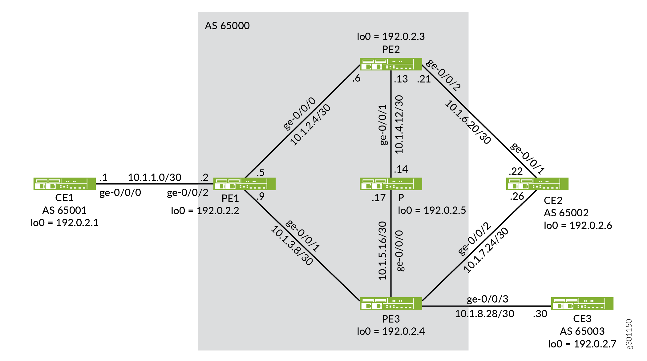
Table 3 shows the list of IP addresses used in this example for quick reference.
|
Device |
AS |
Device ID |
Interface |
Interface IP Address |
|---|---|---|---|---|
|
CE1 |
65001 |
192.0.2.1/32 |
ge-0/0/0.0 |
10.1.1.1/30 |
|
PE1 |
65000 |
192.0.2.2/32 |
ge-0/0/2.0 |
10.1.1.2/30 |
|
ge-0/0/0.0 |
10.1.2.5/30 |
|||
|
ge-0/0/1.0 |
10.1.3.9/30 |
|||
|
PE2 |
65000 |
192.0.2.3/32 |
ge-0/0/0.0 |
10.1.2.6/30 |
|
ge-0/0/1.0 |
10.1.4.13/30 |
|||
|
ge-0/0/2.0 |
10.1.6.21/30 |
|||
|
PE3 |
65000 |
192.0.2.4/32 |
ge-0/0/1.0 |
10.1.3.10/30 |
|
ge-0/0/0.0 |
10.1.5.18/30 |
|||
|
ge-0/0/2.0 |
10.1.7.25/30 |
|||
|
ge-0/0/3.0 |
10.1.8.29/30 |
|||
|
P |
65000 |
192.0.2.5/32 |
ge-0/0/1.0 |
10.1.4.14/30 |
|
ge-0/0/0.0 |
10.1.5.17/30 |
|||
|
CE2 |
65002 |
192.0.2.6/32 |
ge-0/0/1.0 |
10.1.6.22/30 |
|
ge-0/0/2.0 |
10.1.7.26/30 |
|||
|
CE3 |
65003 |
192.0.2.7/32 |
ge-0/0/3.0 |
10.1.8.30/30 |
This example was tested using logical systems (logical routers). Therefore all the physical interfaces in the example are the same and the configuration is done on separate logical interfaces. In an non-test network, you will use separate physical routers and separate physical interfaces for the connections to other devices.
Configuration
Procedure
CLI Quick Configuration
To quickly configure this example, copy the
following commands, paste them into a text file, remove any line breaks,
change any details necessary to match your network configuration,
and then copy and paste the commands into the CLI at the [edit] hierarchy level.
Device CE1
set interfaces ge-0/0/0 unit 0 family inet address 10.1.1.1/30
set interfaces ge-0/0/0 unit 0 family mpls
set interfaces ge-0/0/0 unit 0 description toPE1
set interfaces lo0 unit 0 family inet address 192.0.2.1/32
set routing-options router-id 192.0.2.1
set routing-options autonomous-system 65001
set protocols bgp group toPE1 type external
set protocols bgp group toPE1 export send-direct
set protocols bgp group toPE1 peer-as 65000
set protocols bgp group toPE1 neighbor 10.1.1.2
set policy-options policy-statement send-direct from protocol direct
set policy-options policy-statement send-direct then accept
Device PE1
set interfaces ge-0/0/2 unit 0 family inet address 10.1.1.2/30
set interfaces ge-0/0/2 unit 0 family mpls
set interfaces ge-0/0/2 unit 0 description toCE1
set interfaces ge-0/0/0 unit 0 family inet address 10.1.2.5/30
set interfaces ge-0/0/0 unit 0 family mpls
set interfaces ge-0/0/0 unit 0 description toPE2
set interfaces ge-0/0/1 unit 0 family inet address 10.1.3.9/30
set interfaces ge-0/0/1 unit 0 family mpls
set interfaces ge-0/0/1 unit 0 description toPE3
set interfaces lo0 unit 0 family inet address 192.0.2.2/32
set protocols mpls interface all
set protocols ldp interface all
set protocols ospf area 0.0.0.0 interface lo0.0 passive
set protocols ospf area 0.0.0.0 interface ge-0/0/0.0 metric 10
set protocols ospf area 0.0.0.0 interface ge-0/0/1.0 metric 10
set protocols bgp group toInternal type internal
set protocols bgp group toInternal family inet-vpn unicast
set protocols bgp group toInternal local-address 192.0.2.2
set protocols bgp group toInternal neighbor 192.0.2.3
set protocols bgp group toInternal neighbor 192.0.2.4
set routing-options router-id 192.0.2.2
set routing-options autonomous-system 65000
set routing-options forwarding-table export lb
set routing-instances toCE1 instance-type vrf
set routing-instances toCE1 interface ge-0/0/2.0
set routing-instances toCE1 route-distinguisher 65000:1
set routing-instances toCE1 vrf-target target:65000:1
set routing-instances toCE1 vrf-table-label
set routing-instances toCE1 protocols bgp group toCE1 type external
set routing-instances toCE1 protocols bgp group toCE1 peer-as 65001
set routing-instances toCE1 protocols bgp group toCE1 neighbor 10.1.1.1
set routing-instances toCE1 routing-options multipath vpn-unequal-cost equal-external-internal
set policy-options policy-statement lb then load-balance per-packet
Device PE2
set interfaces ge-0/0/0 unit 0 family inet address 10.1.2.6/30
set interfaces ge-0/0/0 unit 0 family mpls
set interfaces ge-0/0/0 unit 0 description toPE1
set interfaces ge-0/0/1 unit 0 family inet address 10.1.4.13/30
set interfaces ge-0/0/1 unit 0 family mpls
set interfaces ge-0/0/1 unit 0 description toP
set interfaces ge-0/0/2 unit 0 family inet address 10.1.6.21/30
set interfaces ge-0/0/2 unit 0 family mpls
set interfaces ge-0/0/2 unit 0 description toCE2
set interfaces lo0 unit 0 family inet address 192.0.2.3/32
set protocols mpls interface all
set protocols ldp interface all
set protocols ospf area 0.0.0.0 interface lo0.0 passive
set protocols ospf area 0.0.0.0 interface ge-0/0/0.0 metric 10
set protocols ospf area 0.0.0.0 interface ge-0/0/1.0 metric 5
set protocols bgp group toInternal type internal
set protocols bgp group toInternal family inet-vpn unicast
set protocols bgp group toInternal local-address 192.0.2.3
set protocols bgp group toInternal neighbor 192.0.2.2
set protocols bgp group toInternal neighbor 192.0.2.4
set routing-options router-id 192.0.2.3
set routing-options autonomous-system 65000
set routing-options forwarding-table export lb
set routing-instances toCE2 instance-type vrf
set routing-instances toCE2 interface ge-0/0/2.0
set routing-instances toCE2 route-distinguisher 65000:1
set routing-instances toCE2 vrf-target target:65000:1
set routing-instances toCE2 vrf-table-label
set routing-instances toCE2 protocols bgp group toCE2 type external
set routing-instances toCE2 protocols bgp group toCE2 peer-as 65002
set routing-instances toCE2 protocols bgp group toCE2 neighbor 10.1.6.22
set routing-instances toCE2 routing-options multipath vpn-unequal-cost equal-external-internal
set policy-options policy-statement lb then load-balance per-packet
Device PE3
set interfaces ge-0/0/1 unit 0 family inet address 10.1.3.10/30
set interfaces ge-0/0/1 unit 0 family mpls
set interfaces ge-0/0/1 unit 0 description toPE1
set interfaces ge-0/0/0 unit 0 family inet address 10.1.5.18/30
set interfaces ge-0/0/0 unit 0 family mpls
set interfaces ge-0/0/0 unit 0 description toP
set interfaces ge-0/0/2 unit 0 family inet address 10.1.7.25/30
set interfaces ge-0/0/2 unit 0 family mpls
set interfaces ge-0/0/2 unit 0 description toCE2
set interfaces ge-0/0/3 unit 0 family inet address 10.1.8.29/30
set interfaces ge-0/0/3 unit 0 family mpls
set interfaces ge-0/0/3 unit 0 description toCE3
set interfaces lo0 unit 0 family inet address 192.0.2.4/32
set protocols mpls interface all
set protocols ldp interface all
set protocols ospf area 0.0.0.0 interface lo0.0 passive
set protocols ospf area 0.0.0.0 interface ge-0/0/1.0 metric 10
set protocols ospf area 0.0.0.0 interface ge-0/0/0.0 metric 5
set protocols bgp group toInternal type internal
set protocols bgp group toInternal local-address 192.0.2.4
set protocols bgp group toInternal family inet-vpn unicast
set protocols bgp group toInternal family route-target
set protocols bgp group toInternal neighbor 192.0.2.2
set protocols bgp group toInternal neighbor 192.0.2.3
set routing-options router-id 192.0.2.4
set routing-options autonomous-system 65000
set routing-options forwarding-table export lb
set routing-instances toCE2_3 instance-type vrf
set routing-instances toCE2_3 interface ge-0/0/2.0
set routing-instances toCE2_3 interface ge-0/0/3.0
set routing-instances toCE2_3 route-distinguisher 65000:1
set routing-instances toCE2_3 vrf-target target:65000:1
set routing-instances toCE2_3 vrf-table-label
set routing-instances toCE2_3 protocols bgp group toCE2 type external
set routing-instances toCE2_3 protocols bgp group toCE2 peer-as 65002
set routing-instances toCE2_3 protocols bgp group toCE2 neighbor 10.1.7.26
set routing-instances toCE2_3 protocols bgp group toCE3 type external
set routing-instances toCE2_3 protocols bgp group toCE3 peer-as 65003
set routing-instances toCE2_3 protocols bgp group toCE3 neighbor 10.1.8.30
set routing-instances toCE2_3 routing-options multipath vpn-unequal-cost equal-external-internal
set policy-options policy-statement lb then load-balance per-packet
Device P
set interfaces ge-0/0/1 unit 0 family inet address 10.1.4.14/30
set interfaces ge-0/0/1 unit 0 family mpls
set interfaces ge-0/0/1 unit 0 description toPE2
set interfaces ge-0/0/0 unit 0 family inet address 10.1.5.17/30
set interfaces ge-0/0/0 unit 0 family mpls
set interfaces ge-0/0/0 unit 0 description toPE3
set interfaces lo0 unit 0 family inet address 192.0.2.5/32
set protocols mpls interface all
set protocols ldp interface all
set protocols ospf area 0.0.0.0 interface lo0.0 passive
set protocols ospf area 0.0.0.0 interface ge-0/0/1.0 metric 5
set protocols ospf area 0.0.0.0 interface ge-0/0/0.0 metric 5
set routing-options router-id 192.0.2.5
set routing-options autonomous-system 65000
Device CE2
set interfaces ge-0/0/1 unit 0 family inet address 10.1.6.22/30
set interfaces ge-0/0/1 unit 0 family mpls
set interfaces ge-0/0/1 unit 0 description toPE2
set interfaces ge-0/0/2 unit 0 family inet address 10.1.7.26/30
set interfaces ge-0/0/2 unit 0 family mpls
set interfaces ge-0/0/2 unit 0 description toPE3
set interfaces lo0 unit 0 family inet address 192.0.2.6/32
set routing-options router-id 192.0.2.6
set routing-options autonomous-system 65002
set protocols bgp group toPE2PE3 type external
set protocols bgp group toPE2PE3 export send-direct
set protocols bgp group toPE2PE3 peer-as 65000
set protocols bgp group toPE2PE3 neighbor 10.1.6.21
set protocols bgp group toPE2PE3 neighbor 10.1.7.25
set policy-options policy-statement send-direct from protocol direct
set policy-options policy-statement send-direct then accept
Device CE3
set interfaces ge-0/0/3 unit 0 family inet address 10.1.8.30/30
set interfaces ge-0/0/3 unit 0 family mpls
set interfaces ge-0/0/3 unit 0 description toPE3
set interfaces lo0 unit 0 family inet address 192.0.2.7/32
set routing-options router-id 192.0.2.7
set routing-options autonomous-system 65003
set protocols bgp group toPE3 type external
set protocols bgp group toPE3 export send-direct
set protocols bgp group toPE3 peer-as 65000
set protocols bgp group toPE3 neighbor 10.1.8.29
set policy-options policy-statement send-direct from protocol direct
set policy-options policy-statement send-direct then accept
Step-by-Step Procedure
The following example requires that you navigate various levels in the configuration hierarchy. For information about navigating the CLI, see Using the CLI Editor in Configuration Mode in the CLI User Guide.
To configure unequal-cost load balancing across the VPN setup:
-
Configure the router ID on Device CE1, and assign the device to its autonomous system.
[edit routing-options]
user@CE1# set router-id 192.0.2.1
user@CE1# set autonomous-system 65001
Similarly, configure all other devices.
-
Configure BGP groups for traffic through the entire network.
-
Configure the BGP group for traffic to and from the MPLS network (CE devices).
[edit protocols bgp group toPE1]
user@CE1# set type external
user@CE1# set peer-as 65000
user@CE1# set neighbor 10.1.1.2
-
Configure similar BGP groups (
to AS 65000andtoPE3) on Devices CE2 and CE3 by modifying thepeer-asandneighborstatements accordingly. -
Configure the BGP group for traffic through the MPLS network (PE devices).
[edit protocols bgp group toInternal]
user@PE1# set type internal
user@PE1# set family inet-vpn unicast
user@PE1# set local-address 192.0.2.2
user@PE1# set neighbor 192.0.2.3
user@PE1# set neighbor 192.0.2.4
-
Configure the same BGP group (
toInternal) on Devices PE2 and PE3 by modifying thelocal-addressandneighborstatements accordingly.
-
-
Configure a routing policy for exporting routes to and from the MPLS network (
send-directpolicy) and a policy for load balancing traffic network across the MPLS network (lbpolicy).-
Configure a policy (
send-direct) for exporting routes from the routing table into BGP on Device CE1.[edit policy-options policy-statement send-direct] user@CE1# set from protocol direct user@CE1# set then accept
[edit protocols bgp group toPE1]
user@CE1# set export send-direct
Similarly, configure the
send-directpolicy on Devices CE2 and CE3. -
Configure a policy (
lb) for exporting routes from the routing table into the forwarding table on Device PE1.The
lbpolicy configures per-packet load balancing, which ensures that all next-hop addresses for a destination are installed in the forwarding table.[edit policy-options policy-statement lb] user@PE1# set then load-balance per-packet
[edit routing-options]
user@PE1# set forwarding-table export lb
Similarly, configure the
lbpolicy on Devices PE2, and PE3.
-
-
Configure the following:
-
Configure the routing instance on the PE devices for exporting routes through the autonomous systems.
-
Include the
equal-external-internalstatement at the[edit routing-instances instance-name routing-options multipath vpn-unequal-cost]hierarchy level to enable load balancing in the network. -
Include the
vrf-table-labelstatement at the[edit routing-instances instance-name]hierarchy level for filtering traffic prior to exiting the egress device (Device CE3).
Device PE1
[edit routing-instances toCE1]
user@PE1# set instance-type vrf
user@PE1# set interface ge-0/0/2.0
user@PE1# set route-distinguisher 65000:1
user@PE1# set vrf-target target:65000:1
user@PE1# set vrf-table-label
user@PE1# set protocols bgp group toCE1 type external
user@PE1# set protocols bgp group toCE1 peer-as 65001
user@PE1# set protocols bgp group toCE1 neighbor 10.1.1.1
user@PE1# set routing-options multipath vpn-unequal-cost equal-external-internal
Device PE2
[edit routing-instances toCE1]
user@PE2# set instance-type vrf
user@PE2# set interface ge-0/0/2.0
user@PE2# set route-distinguisher 65000:1
user@PE2# set vrf-target target:65000:1
user@PE2# set vrf-table-label
user@PE2# set protocols bgp group toCE2 type external
user@PE2# set protocols bgp group toCE2 peer-as 65002
user@PE2# set protocols bgp group toCE2 neighbor 10.1.6.22
user@PE2# set routing-options multipath vpn-unequal-cost equal-external-internal
Device PE3
[edit routing-instances toCE2_3]
user@PE3# set instance-type vrf
user@PE3# set interface ge-0/0/2.0
user@PE3# set interface ge-0/0/3.0
user@PE3# set route-distinguisher 65000:1
user@PE3# set vrf-target target:65000:1
user@PE3# set vrf-table-label
user@PE3# set protocols bgp group toCE2 type external
user@PE3# set protocols bgp group toCE2 peer-as 65002
user@PE3# set protocols bgp group toCE2 neighbor 10.1.7.26
user@PE3# set protocols bgp group toCE3 type external
user@PE3# set protocols bgp group toCE3 peer-as 65003
user@PE3# set protocols bgp group toCE3 neighbor 10.1.8.30
user@PE3# set routing-options multipath vpn-unequal-cost equal-external-internal
-
Results
From configuration mode, confirm your configuration
by entering the show configuration command. If the output
does not display the intended configuration, repeat the instructions
in this example to correct the configuration. The following is a snippet
from the show configuration output for PE3.
user@PE3#

                     show configuration


interfaces {
    ge-0/0/0 {
        unit 0 {
            description toP;
            family inet {
                address 10.1.5.18/30;
            }
            family mpls;
        }
    }
    ge-0/0/1 {
        unit 0 {
            description toPE1;
            family inet {
                address 10.1.3.10/30;
            }
            family mpls;
        }
    }
    ge-0/0/2 {
        unit 0 {
            description toCE2;
            family inet {
                address 10.1.7.25/30;
            }
            family mpls;
        }
    }
    ge-0/0/3 {
        unit 0 {
            description toCE3;
            family inet {
                address 10.1.8.29/30;
            }
            family mpls;
        }
    }
    lo0 {
        unit 0 {
            family inet {
                address 192.0.2.4/32;
            }
        }
    }
}
policy-options {
    policy-statement lb {
        then {
            load-balance per-packet;
        }
    }
}
routing-instances {
    toCE2_3 {
        routing-options {
            multipath {
                vpn-unequal-cost equal-external-internal;
            }
        }
        protocols {
            bgp {
                group toCE2 {
                    type external;
                    peer-as 65002;
                    neighbor 10.1.7.26;
                }
                group toCE3 {
                    type external;
                    peer-as 65003;
                    neighbor 10.1.8.30;
                }
            }
        }
        instance-type vrf;
        interface ge-0/0/2.0;
        interface ge-0/0/3.0;
        route-distinguisher 65000:1;
        vrf-target target:65000:1;
        vrf-table-label;
    }
}
routing-options {
    forwarding-table {
        export lb;
    }
    router-id 192.0.2.4;
    autonomous-system 65000;
}
protocols {
    ospf {
        area 0.0.0.0 {
            interface lo0.0 {
                passive;
            }
            interface ge-0/0/1.0 {
                metric 10;
            }
            interface ge-0/0/0.0 {
                metric 5;
            }
        }
    }
    bgp {
        group toInternal {
            type internal;
            local-address 192.0.2.4;
            family inet-vpn {
                unicast;
            }
            family route-target;
            neighbor 192.0.2.2;
            neighbor 192.0.2.3;
        }
    }
    ldp {
        interface all;
    }
    mpls {
        interface all;
    }
}
If you are done configuring the device, enter commit from configuration mode.
Verification
Confirm that the configuration is working properly.
Verifying BGP
Purpose
Verify that BGP is working.
Action
From operational mode, run the show route protocol
bgp command.
user@PE3> show route protocol bgp

inet.0: 19 destinations, 19 routes (19 active, 0 holddown, 0 hidden)

inet.3: 3 destinations, 3 routes (3 active, 0 holddown, 0 hidden)

toCE2_3.inet.0: 9 destinations, 14 routes (9 active, 0 holddown, 0 hidden)
@ = Routing Use Only, # = Forwarding Use Only
+ = Active Route, - = Last Active, * = Both

10.1.1.0/30        *[BGP/170] 6d 19:24:16, localpref 100, from 192.0.2.2
                      AS path: I, validation-state: unverified
                    >  to 10.1.3.9 via ge-0/0/1.0, Push 16
10.1.6.20/30       *[BGP/170] 6d 19:24:12, localpref 100, from 192.0.2.3
                      AS path: I, validation-state: unverified
                    >  to 10.1.5.17 via ge-0/0/0.0, Push 16, Push 299808(top)
                    [BGP/170] 6d 17:53:50, localpref 100
                      AS path: 65002 I, validation-state: unverified
                    >  to 10.1.7.26 via ge-0/0/2.0
10.1.7.24/30        [BGP/170] 6d 17:53:50, localpref 100
                      AS path: 65002 I, validation-state: unverified
                    >  to 10.1.7.26 via ge-0/0/2.0
10.1.8.28/30        [BGP/170] 6d 17:55:03, localpref 100
                      AS path: 65003 I, validation-state: unverified
                    >  to 10.1.8.30 via ge-0/0/3.0
192.0.2.1/32       *[BGP/170] 6d 19:24:16, localpref 100, from 192.0.2.2
                      AS path: 65001 I, validation-state: unverified
                    >  to 10.1.3.9 via ge-0/0/1.0, Push 16
192.0.2.6/32       @[BGP/170] 6d 17:53:50, localpref 100
                      AS path: 65002 I, validation-state: unverified
                    >  to 10.1.7.26 via ge-0/0/2.0
                    [BGP/170] 6d 17:53:50, localpref 100, from 192.0.2.3
                      AS path: 65002 I, validation-state: unverified
                    >  to 10.1.5.17 via ge-0/0/0.0, Push 16, Push 299808(top)
192.0.2.7/32       *[BGP/170] 6d 17:55:03, localpref 100
                      AS path: 65003 I, validation-state: unverified
                    >  to 10.1.8.30 via ge-0/0/3.0

mpls.0: 12 destinations, 12 routes (12 active, 0 holddown, 0 hidden)

bgp.l3vpn.0: 4 destinations, 4 routes (4 active, 0 holddown, 0 hidden)
+ = Active Route, - = Last Active, * = Both

65000:1:10.1.1.0/30
                   *[BGP/170] 6d 19:24:16, localpref 100, from 192.0.2.2
                      AS path: I, validation-state: unverified
                    >  to 10.1.3.9 via ge-0/0/1.0, Push 16
65000:1:10.1.6.20/30
                   *[BGP/170] 6d 19:24:12, localpref 100, from 192.0.2.3
                      AS path: I, validation-state: unverified
                    >  to 10.1.5.17 via ge-0/0/0.0, Push 16, Push 299808(top)
65000:1:192.0.2.1/32
                   *[BGP/170] 6d 19:24:16, localpref 100, from 192.0.2.2
                      AS path: 65001 I, validation-state: unverified
                    >  to 10.1.3.9 via ge-0/0/1.0, Push 16
65000:1:192.0.2.6/32
                   *[BGP/170] 6d 17:53:50, localpref 100, from 192.0.2.3
                      AS path: 65002 I, validation-state: unverified
                    >  to 10.1.5.17 via ge-0/0/0.0, Push 16, Push 299808(top)

inet6.0: 1 destinations, 1 routes (1 active, 0 holddown, 0 hidden)

toCE2_3.inet6.0: 1 destinations, 1 routes (1 active, 0 holddown, 0 hidden)

bgp.rtarget.0: 2 destinations, 2 routes (2 active, 0 holddown, 0 hidden)
The output lists the BGP routes installed into the routing table. The lines of output that start with 192.0.2.1/32, 10.1.1.0/30, and 65000:1:192.0.2.1/32 show the BGP routes to Device CE1, which is in AS 65001. The lines of output that start with 192.0.2.6/32, 65000:1:192.0.2.6/32, and 65000:1:10.1.6.20/30 show the BGP routes to Device CE2, which is in AS 65002. The line of output that starts with 192.0.2.7/32 shows the BGP route to Device CE3, which is in AS 65003.
Meaning
BGP is functional in the network.
Verifying Load Balancing
Purpose
Verify that forwarding is taking place in both directions by checking:
-
If both next hops are installed in the forwarding table for a route.
-
If external BGP routes are installed in the forwarding table for a route.
Action
From operational mode, run the show route forwarding-table and show route forwarding-table destination <destination IP> commands.
user@PE3> show route forwarding-table

Routing table: default.inet
Internet:
Destination        Type RtRef Next hop           Type Index    NhRef Netif
default            perm     1                    rjct       36     2
0.0.0.0/32         perm     0                    dscd       34     1
10.1.2.4/30        user     0                    ulst  1048576     2
                              10.1.5.17          ucst      625    12 ge-0/0/0.0
                              10.1.3.9           ucst      617     8 ge-0/0/1.0
10.1.3.8/30        intf     0                    rslv      604     1 ge-0/0/1.0
10.1.3.8/32        dest     0 10.1.3.8           recv      602     1 ge-0/0/1.0
10.1.3.9/32        dest     0 0:50:56:93:63:e7   ucst      617     8 ge-0/0/1.0
10.1.3.10/32       intf     0 10.1.3.10          locl      603     2
10.1.3.10/32       dest     0 10.1.3.10          locl      603     2
10.1.3.11/32       dest     0 10.1.3.11          bcst      601     1 ge-0/0/1.0
10.1.4.12/30       user     0 10.1.5.17          ucst      625    12 ge-0/0/0.0
10.1.5.16/30       intf     0                    rslv      600     1 ge-0/0/0.0
10.1.5.16/32       dest     0 10.1.5.16          recv      598     1 ge-0/0/0.0
10.1.5.17/32       dest     0 0:50:56:93:f8:ff   ucst      625    12 ge-0/0/0.0
10.1.5.18/32       intf     0 10.1.5.18          locl      599     2
10.1.5.18/32       dest     0 10.1.5.18          locl      599     2
10.1.5.19/32       dest     0 10.1.5.19          bcst      597     1 ge-0/0/0.0
192.0.2.2/32       user     1 10.1.3.9           ucst      617     8 ge-0/0/1.0
192.0.2.3/32       user     1 10.1.5.17          ucst      625    12 ge-0/0/0.0
192.0.2.4/32       intf     0 192.0.2.4          locl      607     1
192.0.2.5/32       user     1 10.1.5.17          ucst      625    12 ge-0/0/0.0
224.0.0.0/4        perm     1                    mdsc       35     1
224.0.0.1/32       perm     0 224.0.0.1          mcst       31     5
224.0.0.2/32       user     1 224.0.0.2          mcst       31     5
224.0.0.5/32       user     1 224.0.0.5          mcst       31     5
255.255.255.255/32 perm     0                    bcst       32     1

Routing table: __master.anon__.inet
Internet:
Destination        Type RtRef Next hop           Type Index    NhRef Netif
default            perm     0                    rjct      524     1
0.0.0.0/32         perm     0                    dscd      522     1
224.0.0.0/4        perm     0                    mdsc      523     1
224.0.0.1/32       perm     0 224.0.0.1          mcst      526     1
255.255.255.255/32 perm     0                    bcst      527     1

Routing table: toCE2_3.inet
Internet:
Destination        Type RtRef Next hop           Type Index    NhRef Netif
default            perm     0                    rjct      566     1
0.0.0.0/32         perm     0                    dscd      564     1
10.1.1.0/30        user     0                    indr  1048574     3
                              10.1.3.9          Push 16      623     2 ge-0/0/1.0
10.1.6.20/30       user     0                    indr  1048575     3
                              10.1.5.17         Push 16, Push 299808(top)      629     2 ge-0/0/0.0
10.1.7.24/30       intf     0                    rslv      616     1 ge-0/0/2.0
10.1.7.24/32       dest     0 10.1.7.24          recv      614     1 ge-0/0/2.0
10.1.7.25/32       intf     0 10.1.7.25          locl      615     2
10.1.7.25/32       dest     0 10.1.7.25          locl      615     2
10.1.7.26/32       dest     1 0:50:56:93:86:18   ucst      618     4 ge-0/0/2.0
10.1.7.27/32       dest     0 10.1.7.27          bcst      613     1 ge-0/0/2.0
10.1.8.28/30       intf     0                    rslv      612     1 ge-0/0/3.0
10.1.8.28/32       dest     0 10.1.8.28          recv      610     1 ge-0/0/3.0
10.1.8.29/32       intf     0 10.1.8.29          locl      611     2
10.1.8.29/32       dest     0 10.1.8.29          locl      611     2
10.1.8.30/32       dest     1 0:50:56:93:bb:ed   ucst      622     4 ge-0/0/3.0
10.1.8.31/32       dest     0 10.1.8.31          bcst      609     1 ge-0/0/3.0
192.0.2.1/32       user     0                    indr  1048574     3
                              10.1.3.9          Push 16      623     2 ge-0/0/1.0
192.0.2.6/32       user     0                    ulst  1048577     2
                              10.1.7.26          ucst      618     4 ge-0/0/2.0
                                                 indr  1048575     3
                              10.1.5.17         Push 16, Push 299808(top)      629     2 ge-0/0/0.0
192.0.2.7/32       user     0 10.1.8.30          ucst      622     4 ge-0/0/3.0
224.0.0.0/4        perm     0                    mdsc      565     1
224.0.0.1/32       perm     0 224.0.0.1          mcst      568     1
255.255.255.255/32 perm     0                    bcst      569     1
...
In the default.inet routing table, which is the forwarding table, the line of output that starts with 10.1.2.4/30 shows that for a route to Device PE2 in the same AS, two next hops are installed in the table: 10.1.3.9 and 10.1.5.17.
In the toCE2_3.inet routing table, which is the external routing table, the line of output that starts with 192.0.2.6/32 shows that for a route to Device CE2 in AS 65002, an internal next hop of 10.1.5.17 and an external next hop of 10.1.7.26 are installed in the table. This indicates that both internal and external BGP routes are operational in the network.
user@PE3> show route forwarding-table destination 10.1.2.6

Routing table: default.inet
Internet:
Destination        Type RtRef Next hop           Type Index    NhRef Netif
10.1.2.4/30        user     0                    ulst  1048576     2
                              10.1.5.17          ucst      625    12 ge-0/0/0.0
                              10.1.3.9           ucst      617     8 ge-0/0/1.0

Routing table: __pfe_private__.inet
Internet:
Destination        Type RtRef Next hop           Type Index    NhRef Netif
default            perm     0                    dscd      513     2

Routing table: __master.anon__.inet
Internet:
Destination        Type RtRef Next hop           Type Index    NhRef Netif
default            perm     0                    rjct      524     1

Routing table: __juniper_services__.inet
Internet:
Destination        Type RtRef Next hop           Type Index    NhRef Netif
default            perm     0                    dscd      546     2

Routing table: toCE2_3.inet
Internet:
Destination        Type RtRef Next hop           Type Index    NhRef Netif
default            perm     0                    rjct      630     1
The line of output that starts with 10.1.2.4/30 shows that for a route from Device PE3 to Device PE2 in the same AS, two next hops are installed in the table: 10.1.3.9 through the ge-0/0/1.0 interface, and 10.1.5.17 through the ge-2/1/10.18 interface.
Meaning
Multiple next hops for a route, including external BGP routes, are installed in the forwarding tables.
Configuring Protocol-Independent Load Balancing in Layer 3 VPNs
Protocol-independent load balancing for Layer 3 VPNs allows the forwarding next hops of both the active route and alternative paths to be used for load balancing. Protocol-independent load balancing works in conjunction with Layer 3 VPNs. It supports the load balancing of VPN routes independently of the assigned route distinguisher. When protocol-independent load balancing is enabled, both routes to other PE routers and routes to directly connected CE routers are load-balanced.
When load-balancing information is created for a given route,
the active path is marked as Routing Use Only in the output of the show route table command.
The following sections describe how to configure protocol-independent load balancing and how this configuration can affect routing policies:
Configuring Load Balancing for Layer 3 VPNs
The configuration of protocol-independent load balancing for Layer 3 VPNs is a little different for IPv4 versus IPv6:
IPv4—You only need to configure the
multipathstatement at either the[edit routing-instances routing-instance-name routing-options]hierarchy level or the[edit routing-instances routing-instance-name routing-options rib routing-table-name]hierarchy level.IPv6—You need to configure the
multipathstatement at both the[edit routing-instances routing-instance-name routing-options]hierarchy level and the[edit routing-instances routing-instance-name routing-options rib routing-table-name]hierarchy level.
You cannot configure the multipath statement and
sub-statements at the same time that you have configured the l3vpn statement.
To configure protocol-independent load balancing for Layer 3
VPNs, include the multipath statement:
multipath {
    vpn-unequal-cost equal-external-internal;
}
When you include the multipath statement at the following
hierarchy levels, protocol-independent load balancing is applied to
the default routing table for that routing instance (routing-instance-name.inet.0):
[edit routing-instances routing-instance-name routing-options][edit logical-systems logical-system-name routing-instances routing-instance-name routing-options]
The [edit logical-systems] hierarchy level is not
applicable in ACX Series routers.
When you include the multipath statement at the following
hierarchy levels, protocol-independent load balancing is applied to
the specified routing table:
[edit routing-instances routing-instance-name routing-options rib routing-table-name][edit logical-systems logical-system-name routing-instances routing-instance-name routing-options rib routing-table-name]
The [edit logical-systems] hierarchy level is not
applicable in ACX Series routers.
The vpn-unequal-cost statement is optional:
When you include it, protocol-independent load balancing is applied to VPN routes that are equal until the IGP metric with regard to route selection.
When you do not include it, protocol-independent load balancing is applied to VPN routes that are equal until the router identifier with regard to route selection.
The vpn-unequal-cost statement is not applicable
in ACX Series routers.
The equal-external-internal statement is also optional.
When you include it, protocol-independent load balancing is applied
to both internal and external BGP paths. You can configure this in
conjunction with egress IP header filtering (enabled with the vrf-table-label statement). For more information, see Load Balancing and IP Header Filtering for Layer
3 VPNs.
You can include the vpn-unequal-cost equal-external-internal statement and the l3vpn statement at the [edit routing-options
forwarding-options chained-composite-next-hop ingress] hierarchy
level simultaneously. However, if you do this, EBGP does not work.
This means that when there are both paths with chained next hops and
paths with nonchained next hops as candidates for EBGP equal-cost
multipath (ECMP), the paths using chained next hops are excluded.
In a typical case, the excluded paths are the internal paths.
Configuring Load Balancing and Routing Policies
If you enable protocol-independent load balancing for Layer 3
VPNs by including the multipath statement and if you also
include the load-balance per-packet statement in the routing
policy configuration, packets are not load-balanced.
For example, a PE router has the following VRF routing instance configured:
[edit routing-instances]
load-balance-example {
    instance-type vrf;
    interface fe-0/1/1.0;
    interface fe-0/1/1.1;
    route-distinguisher 2222:2;
    vrf-target target:2222:2;
    routing-options {
        multipath;
    }
    protocols {
        bgp {
            group group-example {
                import import-policy;
                family inet {
                    unicast;
                }
                export export-policy;
                peer-as 4444;
                local-as 3333;
                multipath;
                as-override;
                neighbor 10.12.33.22;
            }
        }
    }
}
The PE router also has the following policy statement configured:
[edit policy-options policy-statement export-policy]
from protocol bgp;
then {
    load-balance per-packet;
}
When you include the multipath statement in the VRF
routing instance configuration, the paths are no longer marked as
BGP paths but are instead marked as multipath paths. Packets from
the PE router are not load-balanced.
To ensure that VPN load-balancing functions as expected, do
not include the from protocol statement in the policy statement
configuration. The policy statement should be configured as follows:
[edit policy-options policy-statement export-policy]
then {
    load-balance per-packet;
}
For more information about how to configure per-packet load balancing, see the Routing Policies, Firewall Filters, and Traffic Policers User Guide.
Example: Configuring PIM Join Load Balancing on Next-Generation Multicast VPN
This example shows how to configure multipath routing for external and internal virtual private network (VPN) routes with unequal interior gateway protocol (IGP) metrics and Protocol Independent Multicast (PIM) join load balancing on provider edge (PE) routers running next-generation multicast VPN (MVPN). This feature allows customer PIM (C-PIM) join messages to be load-balanced across available internal BGP (IBGP) upstream paths when there is no external BGP (EBGP) path present, and across available EBGP upstream paths when external and internal BGP (EIBGP) paths are present toward the source or rendezvous point (RP).
Requirements
This example uses the following hardware and software components:
- Three MX Series routers.
Before you begin:
Configure the device interfaces.
Configure the following routing protocols on all PE routers:
OSPF
MPLS
LDP
PIM
BGP
Configure a multicast VPN.
Overview and Topology
Junos OS supports multipath configuration along with PIM join load balancing. This allows C-PIM join messages to be load-balanced across all available IBGP paths when there are only IBGP paths present, and across all available upstream EBGP paths when EIBGP paths are present toward the source (or RP). Unlike Draft-Rosen MVPN, next-generation MVPN does not utilize unequal EIBGP paths to send C-PIM join messages. This feature is applicable to IPv4 C-PIM join messages.
By default, only one active IBGP path is used to send the C-PIM join messages for a PE router having only IBGP paths toward the source (or RP). When there are EIBGP upstream paths present, only one active EBGP path is used to send the join messages.
In a next-generation MVPN, C-PIM join messages are translated into (or encoded as) BGP customer multicast (C-multicast) MVPN routes and advertised with the BGP MCAST-VPN address family toward the sender PE routers. A PE router originates a C-multicast MVPN route in response to receiving a C-PIM join message through its PE router to customer edge (CE) router interface. The two types of C-multicast MVPN routes are:
Shared tree join route (C-*, C-G)
Originated by receiver PE routers.
Originated when a PE router receives a shared tree C-PIM join message through its PE-CE router interface.
Source tree join route (C-S, C-G)
Originated by receiver PE routers.
Originated when a PE router receives a source tree C-PIM join message (C-S, C-G), or originated by the PE router that already has a shared tree join route and receives a source active autodiscovery route.
The upstream path in a next-generation MVPN is selected using the Bytewise-XOR hash algorithm as specified in Internet draft draft-ietf-l3vpn-2547bis-mcast, Multicast in MPLS/BGP IP VPNs. The hash algorithm is performed as follows:
The PE routers in the candidate set are numbered from lower to higher IP address, starting from 0.
A bytewise exclusive-or of all the bytes is performed on the C-root (source) and the C-G (group) address.
The result is taken modulo n, where n is the number of PE routers in the candidate set. The result is N.
N represents the IP address of the upstream PE router as numbered in Step 1.
During load balancing, if a PE router with one or more upstream IBGP paths toward the source (or RP) discovers a new IBGP path toward the same source (or RP), the C-PIM join messages distributed among previously existing IBGP paths get redistributed due to the change in the candidate PE router set.
In this example, PE1, PE2, and PE3 are the PE routers that have the multipath PIM join load-balancing feature configured. Router PE1 has two EBGP paths and one IBGP upstream path, PE2 has one EBGP path and one IBGP upstream path, and PE3 has two IBGP upstream paths toward the Source. Router CE4 is the customer edge (CE) router attached to PE3. Source and Receiver are the Free BSD hosts.
On PE routers that have EIBGP paths toward the source (or RP), such as PE1 and PE2, PIM join load balancing is performed as follows:
The C-PIM join messages are sent using EBGP paths only. IBGP paths are not used to propagate the join messages.
In Figure 2, the PE1 router distributes the join messages between the two EBGP paths to the CE1 router, and PE2 uses the EBGP path to CE1 to send the join messages.
If a PE router loses one or more EBGP paths toward the source (or RP), the RPF neighbor on the multicast tunnel interface is selected based on a hash mechanism.
On discovering the first EBGP path, only new join messages get load-balanced across available EBGP paths, whereas the existing join messages on the multicast tunnel interface are not redistributed.
If the EBGP path from the PE2 router to the CE1 router goes down, PE2 sends the join messages to PE1 using the IBGP path. When the EBGP path to CE1 is restored, only new join messages that arrive on PE2 use the restored EBGP path, whereas join messages already sent on the IBGP path are not redistributed.
On PE routers that have only IBGP paths toward the source (or RP), such as the PE3 router, PIM join load balancing is performed as follows:
The C-PIM join messages from CE routers get load-balanced only as BGP C-multicast data messages among IBGP paths.
In Figure 2, assuming that the CE4 host is interested in receiving traffic from the Source, and CE4 initiates source join messages for different groups (Group 1 [C-S,C-G1] and Group 2 [C-S,C-G2]), the source join messages arrive on the PE3 router.
Router PE3 then uses the Bytewise-XOR hash algorithm to select the upstream PE router to send the C-multicast data for each group. The algorithm first numbers the upstream PE routers from lower to higher IP address starting from 0.
Assuming that Router PE1 router is numbered 0 and Router PE2 is 1, and the hash result for Group 1 and Group 2 join messages is 0 and 1, respectively, the PE3 router selects PE1 as the upstream PE router to send Group 1 join messages, and PE2 as the upstream PE router to send the Group 2 join messages to the Source.
The shared join messages for different groups [C-*,C-G] are also treated in a similar way to reach the destination.
Configuration
CLI Quick Configuration
To quickly configure this example, copy the
following commands, paste them into a text file, remove any line breaks,
change any details necessary to match your network configuration,
copy and paste the commands into the CLI at the [edit] hierarchy
level, and then enter commit from configuration mode.
PE1
set routing-instances vpn1 instance-type vrf
set routing-instances vpn1 interface ge-3/0/1.0
set routing-instances vpn1 interface ge-3/3/2.0
set routing-instances vpn1 interface lo0.1
set routing-instances vpn1 route-distinguisher 1:1
set routing-instances vpn1 provider-tunnel rsvp-te label-switched-path-template default-template
set routing-instances vpn1 vrf-target target:1:1
set routing-instances vpn1 vrf-table-label
set routing-instances vpn1 routing-options multipath vpn-unequal-cost equal-external-internal
set routing-instances vpn1 protocols bgp export direct
set routing-instances vpn1 protocols bgp group bgp type external
set routing-instances vpn1 protocols bgp group bgp local-address 10.40.10.1
set routing-instances vpn1 protocols bgp group bgp family inet unicast
set routing-instances vpn1 protocols bgp group bgp neighbor 10.40.10.2 peer-as 3
set routing-instances vpn1 protocols bgp group bgp1 type external
set routing-instances vpn1 protocols bgp group bgp1 local-address 10.10.10.1
set routing-instances vpn1 protocols bgp group bgp1 family inet unicast
set routing-instances vpn1 protocols bgp group bgp1 neighbor 10.10.10.2 peer-as 3
set routing-instances vpn1 protocols pim rp static address 10.255.10.119
set routing-instances vpn1 protocols pim interface all
set routing-instances vpn1  protocols pim join-load-balance
set routing-instances vpn1 protocols mvpn mvpn-mode rpt-spt
set routing-instances vpn1 protocols mvpn mvpn-join-load-balance bytewise-xor-hash
PE2
set routing-instances vpn1 instance-type vrf
set routing-instances vpn1 interface ge-1/0/9.0
set routing-instances vpn1 interface lo0.1
set routing-instances vpn1 route-distinguisher 2:2
set routing-instances vpn1 provider-tunnel rsvp-te label-switched-path-template default-template
set routing-instances vpn1 vrf-target target:1:1
set routing-instances vpn1 vrf-table-label
set routing-instances vpn1 routing-options multipath vpn-unequal-cost equal-external-internal
set routing-instances vpn1 protocols bgp export direct
set routing-instances vpn1 protocols bgp group bgp local-address 10.50.10.2
set routing-instances vpn1 protocols bgp group bgp family inet unicast
set routing-instances vpn1 protocols bgp group bgp neighbor 10.50.10.1 peer-as 3
set routing-instances vpn1 protocols pim rp static address 10.255.10.119
set routing-instances vpn1 protocols pim interface all
set routing-instances vpn1 protocols mvpn mvpn-mode rpt-spt
set routing-instances vpn1 protocols mvpn mvpn-join-load-balance bytewise-xor-hash
PE3
set routing-instances vpn1 instance-type vrf
set routing-instances vpn1 interface ge-0/0/8.0
set routing-instances vpn1 interface lo0.1
set routing-instances vpn1 route-distinguisher 3:3
set routing-instances vpn1 provider-tunnel rsvp-te label-switched-path-template default-template
set routing-instances vpn1 vrf-target target:1:1
set routing-instances vpn1 vrf-table-label
set routing-instances vpn1 routing-options multipath vpn-unequal-cost equal-external-internal
set routing-instances vpn1 routing-options autonomous-system 1
set routing-instances vpn1 protocols bgp export direct
set routing-instances vpn1 protocols bgp group bgp type external
set routing-instances vpn1 protocols bgp group bgp local-address 10.80.10.1
set routing-instances vpn1 protocols bgp group bgp family inet unicast
set routing-instances vpn1 protocols bgp group bgp neighbor 10.80.10.2 peer-as 2
set routing-instances vpn1 protocols pim rp static address 10.255.10.119
set routing-instances vpn1 protocols pim interface all
set routing-instances vpn1 protocols mvpn mvpn-mode rpt-spt
set routing-instances vpn1 protocols mvpn mvpn-join-load-balance bytewise-xor-hash
Procedure
Step-by-Step Procedure
The following example requires you to navigate various levels in the configuration hierarchy. For information about navigating the CLI, see Using the CLI Editor in Configuration Mode. To configure the PE1 router:
Repeat this procedure for every Juniper Networks router in the MVPN domain, after modifying the appropriate interface names, addresses, and any other parameters for each router.
Configure a VPN routing forwarding (VRF) routing instance.
[edit routing-instances vpn1]
user@PE1# set instance-type vrf
user@PE1# set interface ge-3/0/1.0
user@PE1# set interface ge-3/3/2.0
user@PE1# set interface lo0.1
user@PE1# set route-distinguisher 1:1
user@PE1# set provider-tunnel rsvp-te label-switched-path-template default-template
user@PE1# set vrf-target target:1:1
user@PE1# set vrf-table-label
Enable protocol-independent load balancing for the VRF instance.
[edit routing-instances vpn1]
user@PE1# set routing-options multipath vpn-unequal-cost equal-external-internal
Configure BGP groups and neighbors to enable PE to CE routing.
[edit routing-instances vpn1 protocols]
user@PE1# set bgp export direct
user@PE1# set bgp group bgp type external
user@PE1# set bgp group bgp local-address 10.40.10.1
user@PE1# set bgp group bgp family inet unicast
user@PE1# set bgp group bgp neighbor 10.40.10.2 peer-as 3
user@PE1# set bgp group bgp1 type external
user@PE1# set bgp group bgp1 local-address 10.10.10.1
user@PE1# set bgp group bgp1 family inet unicast
user@PE1# set bgp group bgp1 neighbor 10.10.10.2 peer-as 3
Configure PIM to enable PE to CE multicast routing.
[edit routing-instances vpn1 protocols]
user@PE1# set pim rp static address 10.255.10.119
Enable PIM on all network interfaces.
[edit routing-instances vpn1 protocols]
user@PE1# set pim interface all
Enable PIM join load balancing for the VRF instance.
[edit routing-instances vpn1 protocols]
user@PE1# set pim join-load-balance
Configure the mode for C-PIM join messages to use rendezvous-point trees, and switch to the shortest-path tree after the source is known.
[edit routing-instances vpn1 protocols]
user@PE1# set mvpn mvpn-mode rpt-spt
Configure the VRF instance to use the Bytewise-XOR hash algorithm.
[edit routing-instances vpn1 protocols]
user@PE1# set mvpn mvpn-join-load-balance bytewise-xor-hash
Results
From configuration mode, confirm your configuration by entering the show routing-instances command. If the output does not display the intended configuration, repeat the instructions in this example to correct the configuration.
user@PE1# show routing-instances
routing-instances {
    vpn1 {
        instance-type vrf;
        interface ge-3/0/1.0;
        interface ge-3/3/2.0;
        interface lo0.1;
        route-distinguisher 1:1;
        provider-tunnel {
            rsvp-te {
                label-switched-path-template {
                    default-template;
                }
            }
        }
        vrf-target target:1:1;
        vrf-table-label;
        routing-options {
            multipath {
                vpn-unequal-cost equal-external-internal;
            }
        }
        protocols {
            bgp {
                export direct;
                group bgp {
                    type external;
                    local-address 10.40.10.1;
                    family inet {
                        unicast;
                    }
                    neighbor 10.40.10.2 {
                        peer-as 3;
                    }
                }
                group bgp1 {
                    type external;
                    local-address 10.10.10.1;
                    family inet {
                        unicast;
                    }
                    neighbor 10.10.10.2 {
                        peer-as 3;
                    }
                }
            }
            pim {
                rp {
                    static {
                        address 10.255.10.119;
                    }
                }
                interface all;
                join-load-balance;
            }
            mvpn {
                mvpn-mode {
                    rpt-spt;
                }
                mvpn-join-load-balance {
                    bytewise-xor-hash;
                }
            }
        }
    }
If you are done configuring the device, enter commit from configuration mode.
Verification
Confirm that the configuration is working properly.
Verifying MVPN C-Multicast Route Information for Different Groups of Join Messages
Purpose
Verify MVPN C-multicast route information for different groups of join messages received on the PE3 router.
Action
From operational mode, run the show mvpn c-multicast command.
user@PE3>
MVPN instance:
Legend for provider tunnel
I-P-tnl -- inclusive provider tunnel S-P-tnl -- selective provider tunnel
Legend for c-multicast routes properties (Pr)
DS -- derived from (*, c-g)          RM -- remote VPN route
Family : INET

Instance : vpn1
  MVPN Mode : RPT-SPT
  C-mcast IPv4 (S:G)            Ptnl                           St
  0.0.0.0/0:203.0.113.1/24        RSVP-TE P2MP:10.255.10.2, 5834,10.255.10.2
  192.0.2.2/24:203.0.113.1/24       RSVP-TE P2MP:10.255.10.2, 5834,10.255.10.2
  0.0.0.0/0:203.0.113.2/24        RSVP-TE P2MP:10.255.10.14, 47575,10.255.10.14
  192.0.2.2/24:203.0.113.2/24       RSVP-TE P2MP:10.255.10.14, 47575,10.255.10.14
Meaning
The output shows how the PE3 router has load-balanced the C-multicast data for the different groups.
For source join messages (S,G):
192.0.2.2/24:203.0.113.1/24 (S,G1) toward the PE1 router (10.255.10.2 is the loopback address of Router PE1).
192.0.2.2/24:203.0.113.2/24 (S,G2) toward the PE2 router (10.255.10.14 is the loopback address of Router PE2).
For shared join messages (*,G):
0.0.0.0/0:203.0.113.1/24 (*,G1) toward the PE1 router (10.255.10.2 is the loopback address of Router PE1).
0.0.0.0/0:203.0.113.2/24 (*,G2) toward the PE2 router (10.255.10.14 is the loopback address of Router PE2).