Logical Systems in a Chassis Cluster
A chassis cluster provides high availability on SRX Series Firewalls where two devices operate as a single device. Chassis cluster includes the synchronization of configuration files and the dynamic runtime session states between the SRX Series Firewalls, which are part of chassis cluster setup. For more information, see the following topics:
Understanding Logical Systems in the Context of Chassis Cluster
The behavior of a chassis cluster whose nodes consist of SRX Series Firewalls running logical systems is the same as that of a cluster whose SRX Series nodes in the cluster are not running logical systems. No difference exists between events that cause a node to fail over. In particular, if a link associated with a single logical system fails, then the device fails over to another node in the cluster.
The primary administrator configures the chassis cluster (including both primary and secondary nodes) before he or she creates and configures the logical systems. Each node in the cluster has the same configuration, as is the case for nodes in a cluster not running logical systems. All logical system configurations are synchronized and replicated between both nodes in the cluster.
When you use SRX Series Firewalls running logical systems within a chassis cluster, you must purchase and install the same number of licenses for each node in the chassis cluster. Logical systems licenses pertain to a single chassis, or node, within a chassis cluster and not to the cluster collectively.
Starting with Junos
OS Release 12.3X48-D50, when you configure the logical systems within
a chassis cluster, if logical systems licenses on backup node are
not sufficient when you commit the configuration, a warning
message is displayed about the number of licenses required on backup
node as well, just as on primary node in all the previous releases.
See Also
Example: Configuring Logical Systems in an Active/Passive Chassis Cluster (Primary Administrators Only)
This example shows how to configure logical systems in a basic active/passive chassis cluster.
The primary administrator configures the chassis cluster and creates logical systems (including an optional interconnect logical system), administrators, and security profiles. Either the primary administrator or the user logical system administrator configures a user logical system. The configuration is synchronized between nodes in the cluster.
Requirements
Before you begin:
-
Obtain two SRX Series Firewalls with identical hardware configurations. See Example: Configuring an Active/Passive Chassis Cluster on SRX5800 Devices. This chassis cluster deployment scenario includes the configuration of the SRX Series Firewall for connections to an MX240 edge router and an EX8208 Ethernet Switch.
-
Physically connect the two devices (back-to-back for the fabric and control ports) and ensure that they are the same models. You can configure both the fabric and control ports on the SRX5000 line. For the SRX1400 or SRX1500 devices or the SRX3000 line, you can configure the fabric ports only. (Platform support depends on the Junos OS release in your installation.) See Connecting SRX Series Devices to Create a Chassis Cluster.
-
Set the chassis cluster ID and node ID on each device and reboot the devices to enable clustering. See Example: Setting the Node ID and Cluster ID for Security Devices in a Chassis Cluster .
For this example, chassis cluster and logical system configuration is performed on the primary (node 0) device at the root level by the primary administrator. Log in to the device as the primary administrator. See Understanding the Primary Logical Systems and the Primary Administrator Role.
When you use SRX Series Firewalls running logical systems in a chassis cluster, you must purchase and install the same number of logical system licenses for each node in the chassis cluster. Logical system licenses pertain to a single chassis or node within a chassis cluster and not to the cluster collectively.
Overview
In this example, the basic active/passive chassis cluster consists of two devices:
-
One device actively provides logical systems, along with maintaining control of the chassis cluster.
-
The other device passively maintains its state for cluster failover capabilities should the active device become inactive.
Logical systems in an active/active chassis cluster are configured in a similar manner as for logical systems in an active/passive chassis cluster. For active/active chassis clusters, there can be multiple redundancy groups that can be primary on different nodes.
The primary administrator configures the following logical systems on the primary device (node 0):
-
Primary logical system—The primary administrator configures a security profile to provision portions of the system’s security resources to the primary logical system and configures the resources of the primary logical system.
-
User logical systems LSYS1 and LSYS2 and their administrators—The primary administrator also configures security profiles to provision portions of the system’s security resources to user logical systems. The user logical system administrator can then configure interfaces, routing, and security resources allocated to his or her logical system.
-
Interconnect logical system LSYS0 that connects logical systems on the device—The primary administrator configures logical tunnel interfaces between the interconnect logical system and each logical system. These peer interfaces effectively allow for the establishment of tunnels.
This example does not describe configuring features such as NAT, IDP, or VPNs for a logical system. See SRX Series Logical Systems Primary Administrator Configuration Tasks Overview and User Logical Systems Configuration Overview for more information about features that can be configured for logical systems.
If you are performing proxy ARP in a chassis cluster configuration, you must apply the proxy ARP configuration to the reth interfaces rather than the member interfaces because the reth interfaces contain the logical configurations. See Configuring Proxy ARP for NAT (CLI Procedure).
Topology
Figure 1 shows the topology used in this example.

Configuration
- Chassis Cluster Configuration (Primary Administrator)
- Logical System Configuration (Primary Administrator)
- User Logical System Configuration (User Logical System Administrator)
Chassis Cluster Configuration (Primary Administrator)
CLI Quick Configuration
To quickly create logical systems and user
logical system administrators and configure the primary and interconnect
logical systems, copy the following commands, paste them into a text
file, remove any line breaks, change any details necessary to match
your network configuration, and then copy and paste the commands into
the CLI at the [edit] hierarchy level.
On {primary:node0}
set chassis cluster control-ports fpc 0 port 0
set chassis cluster control-ports fpc 6 port 0
set interfaces fab0 fabric-options member-interfaces ge-1/1/0
set interfaces fab1 fabric-options member-interfaces ge-7/1/0
set groups node0 system host-name SRX5800-1
set groups node0 interfaces fxp0 unit 0 family inet address 10.157.90.24/9
set groups node0 system backup-router 10.157.64.1 destination 0.0.0.0/0
set groups node1 system host-name SRX5800-2
set groups node1 interfaces fxp0 unit 0 family inet address 10.157.90.23/19
set groups node1 system backup-router 10.157.64.1 destination 0.0.0.0/0
set apply-groups “${node}”
set chassis cluster reth-count 5
set chassis cluster redundancy-group 0 node 0 priority 200
set chassis cluster redundancy-group 0 node 1 priority 100
set chassis cluster redundancy-group 1 node 0 priority 200
set chassis cluster redundancy-group 1 node 1 priority 100
set interfaces ge-1/0/0 gigether-options redundant-parent reth0
set interfaces ge-1/0/1 gigether-options redundant-parent reth1
set interfaces ge-1/0/2 gigether-options redundant-parent reth2
set interfaces ge-1/0/3 gigether-options redundant-parent reth3
set interfaces ge-7/0/0 gigether-options redundant-parent reth0
set interfaces ge-7/0/1 gigether-options redundant-parent reth1
set interfaces ge-7/0/2 gigether-options redundant-parent reth2
set interfaces ge-7/0/3 gigether-options redundant-parent reth3
set interfaces reth0 redundant-ether-options redundancy-group 1
set interfaces reth0 unit 0 family inet address 95.99.99.1/8
set interfaces reth1 redundant-ether-options redundancy-group 1
set interfaces reth2 redundant-ether-options redundancy-group 1
set interfaces reth3 redundant-ether-options redundancy-group 1
Step-by-Step Procedure
The following example requires you to navigate various levels in the configuration hierarchy. For instructions on how to do that, see Using the CLI Editor in Configuration Mode in the Junos OS CLI User Guide.
To configure a chassis cluster:
Perform the following steps on the primary device (node
0). They are automatically copied over to the secondary device (node
1) when you execute a commit command.
-
Configure control ports for the clusters.
[edit chass cluster]
user@host# set control-ports fpc 0 port 0
user@host# set control-ports fpc 6 port 0
-
Configure the fabric (data) ports of the cluster that are used to pass RTOs in active/passive mode.
[edit interfaces]
user@host# set fab0 fabric-options member-interfaces ge-1/1/0
user@host# set fab1 fabric-options member-interfaces ge-7/1/0
-
Assign some elements of the configuration to a specific member. Configure out-of-band management on the fxp0 interface of the SRX Services Gateway using separate IP addresses for the individual control planes of the cluster.
[edit] user@host# set groups node0 system host-name SRX5800-1 user@host# set groups node0 interfaces fxp0 unit 0 family inet address 10.157.90.24/9 user@host# set groups node0 system backup-router 10.157.64.1 destination 0.0.0.0/0 user@host# set groups node1 system host-name SRX5800-2 user@host# set groups node1 interfaces fxp0 unit 0 family inet address 10.157.90.23/19 user@host# set groups node1 system backup-router 10.157.64.1 destination 0.0.0.0/0 user@host# set apply-groups “${node}” -
Configure redundancy groups for chassis clustering.
[edit chassis cluster]
user@host# set reth-count 5
user@host# set redundancy-group 0 node 0 priority 200
user@host# set redundancy-group 0 node 1 priority 100
user@host# set redundancy-group 1 node 0 priority 200
user@host# set redundancy-group 1 node 1 priority 100
-
Configure the data interfaces on the platform so that in the event of a data plane failover, the other chassis cluster member can take over the connection seamlessly.
[edit interfaces]
user@host# set ge-1/0/0 gigether-options redundant-parent reth0
user@host# set ge-1/0/1 gigether-options redundant-parent reth1
user@host# set ge-1/0/2 gigether-options redundant-parent reth2
user@host# set ge-1/0/3 gigether-options redundant-parent reth3
user@host# set ge-7/0/0 gigether-options redundant-parent reth0
user@host# set ge-7/0/1 gigether-options redundant-parent reth1
user@host# set ge-7/0/2 gigether-options redundant-parent reth2
user@host# set ge-7/0/3 gigether-options redundant-parent reth3
user@host# set reth0 redundant-ether-options redundancy-group 1
user@host# set reth0 unit 0 family inet address 95.99.99.1/8
user@host# set reth1 redundant-ether-options redundancy-group 1
user@host# set reth2 redundant-ether-options redundancy-group 1
user@host# set reth3 redundant-ether-options redundancy-group 1
Results
From operational mode, confirm your configuration by
entering the show configuration command. If the output
does not display the intended configuration, repeat the configuration
instructions in this example to correct it.
user@host> show configuration
version ;
groups {
node0 {
system {
host-name SRX58001;
backup-router 10.157.64.1 destination 0.0.0.0/0;
}
interfaces {
fxp0 {
unit 0 {
family inet {
address 10.157.90.24/9;
}
}
}
}
}
node1 {
system {
host-name SRX58002;
backup-router 10.157.64.1 destination 0.0.0.0/0;
}
interfaces {
fxp0 {
unit 0 {
family inet {
address 10.157.90.23/19;
}
}
}
}
}
}
apply-groups "${node}";
chassis {
cluster {
control-link-recovery;
reth-count 5;
control-ports {
fpc 0 port 0;
fpc 6 port 0;
}
redundancy-group 0 {
node 0 priority 200;
node 1 priority 100;
}
redundancy-group 1 {
node 0 priority 200;
node 1 priority 100;
}
}
}
interfaces {
ge-1/0/0 {
gigether–options {
redundant–parent reth0;
}
}
ge-1/0/1 {
gigether–options {
redundant–parent reth1;
}
}
ge-1/0/2 {
gigether–options {
redundant–parent reth2;
}
}
ge-1/0/3 {
gigether–options {
redundant–parent reth3;
}
}
ge-7/0/0 {
gigether–options {
redundant–parent reth0;
}
}
ge-7/0/1 {
gigether–options {
redundant–parent reth1;
}
}
ge-7/0/2 {
gigether–options {
redundant–parent reth2;
}
}
ge-7/0/3 {
gigether–options {
redundant–parent reth3;
}
}
fab0 {
fabric–options {
member–interfaces {
ge-1/1/0;
}
}
}
fab1 {
fabric–options {
member–interfaces {
ge-7/1/0;
}
}
}
reth0 {
redundant–ether–options {
redundancy–group 1;
}
unit 0 {
family inet {
address 95.99.99.1/8;
}
}
}
reth1 {
redundant–ether–options {
redundancy–group 1;
}
}
reth2 {
redundant–ether–options {
redundancy–group 1;
}
}
reth3 {
redundant–ether–options {
redundancy–group 1;
}
}
}Logical System Configuration (Primary Administrator)
CLI Quick Configuration
To quickly create logical systems and user
logical system administrators and configure the primary and interconnect
logical systems, copy the following commands, paste them into a text
file, remove any line breaks, change any details necessary to match
your network configuration, and then copy and paste the commands into
the CLI at the [edit] hierarchy level.
You are prompted to enter and then reenter plain-text passwords.
On {primary:node0}
               set logical-systems LSYS1
set logical-systems LSYS2
set logical-systems LSYS0
set system login class lsys1 logical-system LSYS1
set system login class lsys1 permissions all
set system login user lsys1admin full-name lsys1-admin
set system login user lsys1admin class lsys1
set user lsys1admin authentication plain-text-password
set system login class lsys2 logical-system LSYS2
set system login class lsys2 permissions all
set system login user lsys2admin full-name lsys2-admin
set system login user lsys2admin class lsys2
set system login user lsys2admin authentication plain-text-password
set system security-profile SP-root policy maximum 200
set system security-profile SP-root policy reserved 100
set system security-profile SP-root zone maximum 200
set system security-profile SP-root zone reserved 100
set system security-profile SP-root flow-session maximum 200
set system security-profile SP-root flow-session reserved 100
set system security-profile SP-root root-logical-system
set system security-profile SP0 logical-system LSYS0
set system security-profile SP1 policy maximum 100
set system security-profile SP1 policy reserved 50
set system security-profile SP1 zone maximum 100
set system security-profile SP1 zone reserved 50
set system security-profile SP1 flow-session maximum 100
set system security-profile SP1 flow-session reserved 50
set system security-profile SP1 logical-system LSYS1
set system security-profile SP2 policy maximum 100
set system security-profile SP2 policy reserved 50
set system security-profile SP2 zone maximum 100
set system security-profile SP2 zone reserved 50
set system security-profile SP2 flow-session maximum 100
set system security-profile SP2 flow-session reserved 50
set system security-profile SP2 logical-system LSYS2
set interfaces lt-0/0/0 unit 1 encapsulation ethernet
set interfaces lt-0/0/0 unit 1 peer-unit 0
set interfaces lt-0/0/0 unit 1 family inet address 2.1.1.1/24
set routing-instances vr0 instance-type virtual-router
set routing-instances vr0 interface lt-0/0/0.1
set routing-instances vr0 interface reth0.0
set routing-instances vr0 routing-options static route 85.0.0.0/8 next-hop 2.1.1.3
set routing-instances vr0 routing-options static route 75.0.0.0/8 next-hop 2.1.1.3
set routing-instances vr0 routing-options static route 65.0.0.0/8 next-hop 2.1.1.5
set security zones security-zone root-trust host-inbound-traffic system-services all
set security zones security-zone root-trust host-inbound-traffic protocols all
set security zones security-zone root-trust interfaces reth0.0
set security zones security-zone root-untrust host-inbound-traffic system-services all
set security zones security-zone root-untrust host-inbound-traffic protocols all
set security zones security-zone root-untrust interfaces lt-0/0/0.1
set security policies from-zone root-trust to-zone root-untrust policy root-Trust_to_root-Untrust match source-address any
set security policies from-zone root-trust to-zone root-untrust policy root-Trust_to_root-Untrust match destination-address any
set security policies from-zone root-trust to-zone root-untrust policy root-Trust_to_root-Untrust match application any
set security policies from-zone root-trust to-zone root-untrust policy root-Trust_to_root-Untrust then permit
set security policies from-zone root-untrust to-zone root-trust policy root-Untrust_to_root-Trust match source-address any
set security policies from-zone root-untrust to-zone root-trust policy root-Untrust_to_root-Trust match destination-address any
set security policies from-zone root-untrust to-zone root-trust policy root-Untrust_to_root-Trust match application any
set security policies from-zone root-untrust to-zone root-trust policy root-Untrust_to_root-Trust then permit
set security policies from-zone root-untrust to-zone root-untrust policy root-Untrust_to_root-Untrust match source-address any
set security policies from-zone root-untrust to-zone root-untrust policy root-Untrust_to_root-Untrust match destination-address any
set security policies from-zone root-untrust to-zone root-untrust policy root-Untrust_to_root-Untrust match application any
set security policies from-zone root-untrust to-zone root-untrust policy root-Untrust_to_root-Untrust then permit
set security policies from-zone root-trust to-zone root-trust policy root-Trust_to_root-Trust match source-address any
set security policies from-zone root-trust to-zone root-trust policy root-Trust_to_root-Trust match destination-address any
set security policies from-zone root-trust to-zone root-trust policy root-Trust_to_root-Trust match application any
set security policies from-zone root-trust to-zone root-trust policy root-Trust_to_root-Trust then permit
set logical-systems LSYS0 interfaces lt-0/0/0 unit 0 encapsulation ethernet-vpls
set logical-systems LSYS0 interfaces lt-0/0/0 unit 0 peer-unit 1
set logical-systems LSYS0 interfaces lt-0/0/0 unit 2 encapsulation ethernet-vpls
set logical-systems LSYS0 interfaces lt-0/0/0 unit 2 peer-unit 3
set logical-systems LSYS0 interfaces lt-0/0/0 unit 4 encapsulation ethernet-vpls
set logical-systems LSYS0 interfaces lt-0/0/0 unit 4 peer-unit 5
set logical-systems LSYS0 routing-instances vr instance-type vpls
set logical-systems LSYS0 routing-instances vr interface lt-0/0/0.0
set logical-systems LSYS0 routing-instances vr interface lt-0/0/0.2
set logical-systems LSYS0 routing-instances vr interface lt-0/0/0.4
set logical-systems LSYS1 interfaces lt-0/0/0 unit 3 encapsulation ethernet
set logical-systems LSYS1 interfaces lt-0/0/0 unit 3 peer-unit 2
set logical-systems LSYS1 interfaces lt-0/0/0 unit 3 family inet address 2.1.1.3/24
set logical-systems LSYS2 interfaces lt-0/0/0 unit 5 encapsulation ethernet
set logical-systems LSYS2 interfaces lt-0/0/0 unit 5 peer-unit 4
set logical-systems LSYS2 interfaces lt-0/0/0 unit 5 family inet address 2.1.1.5/24
Step-by-Step Procedure
The following example requires you to navigate various levels in the configuration hierarchy. For instructions on how to do that, see Using the CLI Editor in Configuration Mode.
To create logical systems and user logical system administrators and configure the primary and interconnect logical systems:
-
Create the interconnect and user logical systems.
[edit logical-systems]
user@host# set LSYS0
user@host# set LSYS1
user@host# set LSYS2
-
Configure user logical system administrators.
Step-by-Step Procedure
-
Configure the user logical system administrator for LSYS1.
[edit system login]
user@host# set class lsys1 logical-system LSYS1
user@host# set class lsys1 permissions all
user@host# set user lsys1admin full-name lsys1-admin
user@host# set user lsys1admin class lsys1
user@host# set user lsys1admin authentication plain-text-password
-
Configure the user logical system administrator for LSYS2.
[edit system login]
user@host# set class lsys2 logical-system LSYS2
user@host# set class lsys2 permissions all
user@host# set user lsys2admin full-name lsys2-admin
user@host# set user lsys2admin class lsys2
user@host# set user lsys2admin authentication plain-text-password
-
-
Configure security profiles and assign them to logical systems.
Step-by-Step Procedure
-
Configure a security profile and assign it to the root logical system.
[edit system security-profile]
user@host# set SP-root policy maximum 200
user@host# set SP-root policy reserved 100
user@host# set SP-root zone maximum 200
user@host# set SP-root zone reserved 100
user@host# set SP-root flow-session maximum 200
user@host# set SP-root flow-session reserved 100
user@host# set SP-root root-logical-system
-
Assign a dummy security profile containing no resources to the interconnect logical system LSYS0.
[edit system security-profile]
user@host# set SP0 logical-system LSYS0
-
Configure a security profile and assign it to LSYS1.
[edit system security-profile]
user@host# set SP1 policy maximum 100
user@host# set SP1 policy reserved 50
user@host# set SP1 zone maximum 100
user@host# set SP1 zone reserved 50
user@host# set SP1 flow-session maximum 100
user@host# set SP1 flow-session reserved 50
user@host# set SP1 logical-system LSYS1
-
Configure a security profile and assign it to LSYS2.
[edit system security-profile]
user@host# set SP2 policy maximum 100
user@host# set SP2 policy reserved 50
user@host# set SP2 zone maximum 100
user@host# set SP2 zone reserved 50
user@host# set SP2 flow-session maximum 100
user@host# set SP2 flow-session reserved 50
user@host# set SP2 logical-system LSYS2
-
-
Configure the primary logical system.
Step-by-Step Procedure
-
Configure logical tunnel interfaces.
[edit interfaces]
user@host# set lt-0/0/0 unit 1 encapsulation ethernet
user@host# set lt-0/0/0 unit 1 peer-unit 0
user@host# set lt-0/0/0 unit 1 family inet address 2.1.1.1/24
-
Configure a routing instance.
[edit routing-instances]
user@host# set vr0 instance-type virtual-router
user@host# set vr0 interface lt-0/0/0.1
user@host# set vr0 interface reth0.0
user@host# set vr0 routing-options static route 85.0.0.0/8 next-hop 2.1.1.3
user@host# set vr0 routing-options static route 75.0.0.0/8 next-hop 2.1.1.3
user@host# set vr0 routing-options static route 65.0.0.0/8 next-hop 2.1.1.5
-
Configure zones.
[edit security zones]
user@host# set security-zone root-trust host-inbound-traffic system-services all
user@host# set security-zone root-trust host-inbound-traffic protocols all
user@host# set security-zone root-trust interfaces reth0.0
user@host# set security-zone root-untrust host-inbound-traffic system-services all
user@host# set security-zone root-untrust host-inbound-traffic protocols all
user@host# set security-zone root-untrust interfaces lt-0/0/0.1
-
Configure security policies.
[edit security policies from-zone root-trust to-zone root-untrust]
user@host# set policy root-Trust_to_root-Untrust match source-address any
user@host# set policy root-Trust_to_root-Untrust match destination-address any
user@host# set policy root-Trust_to_root-Untrust match application any
user@host# set policy root-Trust_to_root-Untrust then permit
[edit security policies from-zone root-untrust to-zone root-trust]
user@host# set policy root-Untrust_to_root-Trust match source-address any
user@host# set policy root-Untrust_to_root-Trust match destination-address any
user@host# set policy root-Untrust_to_root-Trust match application any
user@host# set policy root-Untrust_to_root-Trust then permit
[edit security policies from-zone root-untrust to-zone root-untrust]
user@host# set policy root-Untrust_to_root-Untrust match source-address any
user@host# set policy root-Untrust_to_root-Untrust match destination-address any
user@host# set policy root-Untrust_to_root-Untrust match application any
user@host# set policy root-Untrust_to_root-Untrust then permit
[edit security policies from-zone root-trust to-zone root-trust]
user@host# set policy root-Trust_to_root-Trust match source-address any
user@host# set policy root-Trust_to_root-Trust match destination-address any
user@host# set policy root-Trust_to_root-Trust match application any
user@host# set policy root-Trust_to_root-Trust then permit
-
-
Configure the interconnect logical system.
Step-by-Step Procedure
-
Configure logical tunnel interfaces.
[edit logical-systems LSYS0 interfaces]
user@host# set lt-0/0/0 unit 0 encapsulation ethernet-vpls
user@host# set lt-0/0/0 unit 0 peer-unit 1
user@host# set lt-0/0/0 unit 2 encapsulation ethernet-vpls
user@host# set lt-0/0/0 unit 2 peer-unit 3
user@host# set lt-0/0/0 unit 4 encapsulation ethernet-vpls
user@host# set lt-0/0/0 unit 4 peer-unit 5
-
Configure the VPLS routing instance.
[edit logical-systems LSYS0 routing-instances]
user@host# set vr instance-type vpls
user@host# set vr interface lt-0/0/0.0
user@host# set vr interface lt-0/0/0.2
user@host# set vr interface lt-0/0/0.4
-
-
Configure logical tunnel interfaces for the user logical systems.
Step-by-Step Procedure
-
Configure logical tunnel interfaces for LSYS1.
[edit logical-systems LSYS1 interfaces ]
user@host# set lt-0/0/0 unit 3 encapsulation ethernet
user@host# set lt-0/0/0 unit 3 peer-unit 2
user@host# set lt-0/0/0 unit 3 family inet address 2.1.1.3/24
-
Configure logical tunnel interfaces for LSYS2.
[edit logical-systems LSYS2 interfaces ]
user@host# set lt-0/0/0 unit 5 encapsulation ethernet
user@host# set lt-0/0/0 unit 5 peer-unit 4
user@host# set lt-0/0/0 unit 5 family inet address 2.1.1.5/24
-
Results
From configuration mode, confirm the configuration
for LSYS0 by entering the show logical-systems LSYS0 command.
If the output does not display the intended configuration, repeat
the configuration instructions in this example to correct it.
                  [edit]
user@host# show logical-systems LSYS0
interfaces {
    lt-0/0/0 {
        unit 0 {
            encapsulation ethernet-vpls;
            peer-unit 1;
        }
        unit 2 {
            encapsulation ethernet-vpls;
            peer-unit 3;
        }
        unit 4 {
            encapsulation ethernet-vpls;
            peer-unit 5;
        }
    }
}
    routing-instances {
        vr {
            instance-type vpls;
            interface lt-0/0/0.0;
            interface lt-0/0/0.2;
            interface lt-0/0/0.4;
        }
    }
From configuration mode, confirm the configuration for the primary
logical system by entering the show interfaces, show
routing-instances, and show security commands. If
the output does not display the intended configuration, repeat the
configuration instructions in this example to correct it.
                  [edit]
user@host# show interfaces
lt-0/0/0 {
    unit 1 {
        encapsulation ethernet;
        peer-unit 0;
        family inet {
            address 2.1.1.1/24;
        }
    }
}
    ge-1/0/0 {
        gigether-options {
            redundant-parent reth0;
        }
    }
    ge-1/0/1 {
        gigether-options {
            redundant-parent reth1;
        }
    }
    ge-1/0/2 {
        gigether-options {
            redundant-parent reth2;
        }
    }
    ge-1/0/3 {
        gigether-options {
            redundant-parent reth3;
        }
    }
    ge-7/0/0 {
        gigether-options {
            redundant-parent reth0;
        }
    }
    ge-7/0/1 {
        gigether-options {
            redundant-parent reth1;
        }
    }
    ge-7/0/2 {
        gigether-options {
            redundant-parent reth2;
        }
    }
    ge-7/0/3 {
        gigether-options {
            redundant-parent reth3;
        }
    }
    fab0 {
        fabric-options {
            member-interfaces {
                ge-1/1/0;
            }
        }
    }
    fab1 {
        fabric-options {
            member-interfaces {
                ge-7/1/0;
            }
        }
    }
    reth0 {
        redundant-ether-options {
            redundancy-group 1;
        }
        unit 0 {
            family inet {
                address 95.99.99.1/8;
            }
        }
    }
    reth1 {
        redundant-ether-options {
            redundancy-group 1;
        }
    }
    reth2 {
        redundant-ether-options {
            redundancy-group 1;
        }
    }
    reth3 {
        redundant-ether-options {
            redundancy-group 1;
        }
    }
[edit]
user@host# show routing-instances
vr0 {
    instance-type virtual-router;
    interface lt-0/0/0.1;
    interface reth0.0;
    routing-options {
        static {
            route 85.0.0.0/8 next-hop 2.1.1.3;
            route 75.0.0.0/8 next-hop 2.1.1.3;
            route 65.0.0.0/8 next-hop 2.1.1.5;
        }
    }
}
[edit]
user@host# show security
policies {
    from-zone root-trust to-zone root-untrust {
        policy root-Trust_to_root-Untrust {
            match {
                source-address any;
                destination-address any;
                application any;
            }
            then {
                permit;
            }
        }
    }
    from-zone root-untrust to-zone root-trust {
        policy root-Untrust_to_root-Trust {
            match {
                source-address any;
                destination-address any;
                application any;
            }
            then {
                permit;
            }
        }
    }
    from-zone root-untrust to-zone root-untrust {
        policy root-Untrust_to_root-Untrust {
            match {
                source-address any;
                destination-address any;
                application any;
            }
            then {
                permit;
            }
        }
    }
    from-zone root-trust to-zone root-trust {
        policy root-Trust_to_root-Trust {
            match {
                source-address any;
                destination-address any;
                application any;
            }
            then {
                permit;
            }
        }
    }
}
    zones {
        security-zone root-trust {
            host-inbound-traffic {
                system-services {
                    all;
                }
                protocols {
                    all;
                }
            }
            interfaces {
                reth0.0;
            }
        }
        security-zone root-untrust {
            host-inbound-traffic {
                system-services {
                    all;
                }
                protocols {
                    all;
                }
            }
            interfaces {
                lt-0/0/0.1;
            }
        }
    }
If you are done configuring the device, enter commit from configuration mode.
User Logical System Configuration (User Logical System Administrator)
CLI Quick Configuration
To quickly configure user logical systems,
copy the following commands, paste them into a text file, remove any
line breaks, change any details necessary to match your network configuration,
and then copy and paste the commands into the CLI at the [edit] hierarchy level.
Enter the following commands while logged in as the user logical system administrator for LSYS1:
set interfaces reth1 unit 0 family inet address 85.88.88.1/8
set interfaces reth2 unit 0 family inet address 75.77.77.1/8
set routing-instances vr11 instance-type virtual-router
set routing-instances vr11 interface lt-0/0/0.3
set routing-instances vr11 interface reth1.0
set routing-instances vr11 routing-options static route 65.0.0.0/8 next-hop 2.1.1.5
set routing-instances vr11 routing-options static route 95.0.0.0/8 next-hop 2.1.1.1
set routing-instances vr12 instance-type virtual-router
set routing-instances vr12 interface reth2.0
set routing-instances vr12 routing-options interface-routes rib-group inet vr11vr12v4
set routing-instances vr12 routing-options static route 85.0.0.0/8 next-table vr11.inet.0
set routing-instances vr12 routing-options static route 95.0.0.0/8 next-table vr11.inet.0
set routing-instances vr12 routing-options static route 65.0.0.0/8 next-table vr11.inet.0
set routing-instances vr12 routing-options static route 2.1.1.0/24 next-table vr11.inet.0
set routing-options rib-groups vr11vr12v4 import-rib vr11.inet.0
set routing-options rib-groups vr11vr12v4 import-rib vr12.inet.0
set security zones security-zone lsys1-trust host-inbound-traffic system-services all
set security zones security-zone lsys1-trust host-inbound-traffic protocols all
set security zones security-zone lsys1-trust interfaces reth1.0
set security zones security-zone lsys1-trust interfaces lt-0/0/0.3
set security zones security-zone lsys1-untrust host-inbound-traffic system-services all
set security zones security-zone lsys1-untrust host-inbound-traffic protocols all
set security zones security-zone lsys1-untrust interfaces reth2.0
set security policies from-zone lsys1-trust to-zone lsys1-untrust policy lsys1trust-to-lsys1untrust match source-address any
set security policies from-zone lsys1-trust to-zone lsys1-untrust policy lsys1trust-to-lsys1untrust match destination-address any
set security policies from-zone lsys1-trust to-zone lsys1-untrust policy lsys1trust-to-lsys1untrust match application any
set security policies from-zone lsys1-trust to-zone lsys1-untrust policy lsys1trust-to-lsys1untrust then permit
set security policies from-zone lsys1-untrust to-zone lsys1-trust policy lsys1untrust-to-lsys1trust match source-address any
set security policies from-zone lsys1-untrust to-zone lsys1-trust policy lsys1untrust-to-lsys1trust match destination-address any
set security policies from-zone lsys1-untrust to-zone lsys1-trust policy lsys1untrust-to-lsys1trust match application any
set security policies from-zone lsys1-untrust to-zone lsys1-trust policy lsys1untrust-to-lsys1trust then permit
set security policies from-zone lsys1-untrust to-zone lsys1-untrust policy lsys1untrust-to-lsys1untrust match source-address any
set security policies from-zone lsys1-untrust to-zone lsys1-untrust policy lsys1untrust-to-lsys1untrust match destination-address any
set security policies from-zone lsys1-untrust to-zone lsys1-untrust policy lsys1untrust-to-lsys1untrust match application any
set security policies from-zone lsys1-untrust to-zone lsys1-untrust policy lsys1untrust-to-lsys1untrust then permit
set security policies from-zone lsys1-trust to-zone lsys1-trust policy lsys1trust-to-lsys1trust match source-address any
set security policies from-zone lsys1-trust to-zone lsys1-trust policy lsys1trust-to-lsys1trust match destination-address any
set security policies from-zone lsys1-trust to-zone lsys1-trust policy lsys1trust-to-lsys1trust match application any
set security policies from-zone lsys1-trust to-zone lsys1-trust policy lsys1trust-to-lsys1trust then permit
Enter the following commands while logged in as the user logical system administrator for LSYS2:
set interfaces reth3 unit 0 family inet address 65.66.66.1/8
set routing-instances vr2 instance-type virtual-router
set routing-instances vr2 interface lt-0/0/0.5
set routing-instances vr2 interface reth3.0
set routing-instances vr2 routing-options static route 75.0.0.0/8 next-hop 2.1.1.3
set routing-instances vr2 routing-options static route 85.0.0.0/8 next-hop 2.1.1.3
set routing-instances vr2 routing-options static route 95.0.0.0/8 next-hop 2.1.1.1
set security zones security-zone lsys2-trust host-inbound-traffic system-services all
set security zones security-zone lsys2-trust host-inbound-traffic protocols all
set security zones security-zone lsys2-trust interfaces reth3.0
set security zones security-zone lsys2-untrust host-inbound-traffic system-services all
set security zones security-zone lsys2-untrust host-inbound-traffic protocols all
set security zones security-zone lsys2-untrust interfaces lt-0/0/0.5
set security policies from-zone lsys2-trust to-zone lsys2-untrust policy lsys2trust-to-lsys2untrust match source-address any
set security policies from-zone lsys2-trust to-zone lsys2-untrust policy lsys2trust-to-lsys2untrust match destination-address any
set security policies from-zone lsys2-trust to-zone lsys2-untrust policy lsys2trust-to-lsys2untrust match application any
set security policies from-zone lsys2-trust to-zone lsys2-untrust policy lsys2trust-to-lsys2untrust then permit
set security policies from-zone lsys2-untrust to-zone lsys2-trust policy lsys2untrust-to-lsys2trust match source-address any
set security policies from-zone lsys2-untrust to-zone lsys2-trust policy lsys2untrust-to-lsys2trust match destination-address any
set security policies from-zone lsys2-untrust to-zone lsys2-trust policy lsys2untrust-to-lsys2trust match application any
set security policies from-zone lsys2-untrust to-zone lsys2-trust policy lsys2untrust-to-lsys2trust then permit
set security policies from-zone lsys2-untrust to-zone lsys2-untrust policy lsys2untrust-to-lsys2untrust match source-address any
set security policies from-zone lsys2-untrust to-zone lsys2-untrust policy lsys2untrust-to-lsys2untrust match destination-address any
set security policies from-zone lsys2-untrust to-zone lsys2-untrust policy lsys2untrust-to-lsys2untrust match application any
set security policies from-zone lsys2-untrust to-zone lsys2-untrust policy lsys2untrust-to-lsys2untrust then permit
set security policies from-zone lsys2-trust to-zone lsys2-trust policy lsys2trust-to-lsys2trust match source-address any
set security policies from-zone lsys2-trust to-zone lsys2-trust policy lsys2trust-to-lsys2trust match destination-address any
set security policies from-zone lsys2-trust to-zone lsys2-trust policy lsys2trust-to-lsys2trust match application any
set security policies from-zone lsys2-trust to-zone lsys2-trust policy lsys2trust-to-lsys2trust then permit
Step-by-Step Procedure
The user logical system administrator performs the following
configuration while logged in to his or her user logical system. The
primary administrator can also configure a user logical system at
the [edit logical-systems logical-system] hierarchy level.
The following example requires you to navigate various levels in the configuration hierarchy. For instructions on how to do that, see Using the CLI Editor in Configuration Mode.
To configure the LSYS1 user logical system:
-
Configure interfaces.
[edit interfaces]
lsys1-admin@host:LSYS1# set reth1 unit 0 family inet address 85.88.88.1/8
lsys1-admin@host:LSYS1# set reth2 unit 0 family inet address 75.77.77.1/8
-
Configure routing.
[edit routing-instances]
lsys1-admin@host:LSYS1# set vr11 instance-type virtual-router
lsys1-admin@host:LSYS1# set vr11 interface lt-0/0/0.3
lsys1-admin@host:LSYS1# set vr11 interface reth1.0
lsys1-admin@host:LSYS1# set vr11 routing-options static route 65.0.0.0/8 next-hop 2.1.1.5
lsys1-admin@host:LSYS1# set vr11 routing-options static route 95.0.0.0/8 next-hop 2.1.1.1
lsys1-admin@host:LSYS1# set vr12 instance-type virtual-router
lsys1-admin@host:LSYS1# set vr12 interface reth2.0
lsys1-admin@host:LSYS1# set vr12 routing-options interface-routes rib-group inet vr11vr12v4
lsys1-admin@host:LSYS1# set vr12 routing-options static route 85.0.0.0/8 next-table vr11.inet.0
lsys1-admin@host:LSYS1# set vr12 routing-options static route 95.0.0.0/8 next-table vr11.inet.0
lsys1-admin@host:LSYS1# set vr12 routing-options static route 65.0.0.0/8 next-table vr11.inet.0
lsys1-admin@host:LSYS1# set vr12 routing-options static route 2.1.1.0/24 next-table vr11.inet.0
[edit routing-options]
lsys1-admin@host:LSYS1# set rib-groups vr11vr12v4 import-rib vr11.inet.0
lsys1-admin@host:LSYS1# set rib-groups vr11vr12v4 import-rib vr12.inet.0
-
Configure zones and security policies.
[edit security zones]
lsys1-admin@host:LSYS1# set security-zone lsys1-trust host-inbound-traffic system-services all
lsys1-admin@host:LSYS1# set security-zone lsys1-trust host-inbound-traffic protocols all
lsys1-admin@host:LSYS1# set security-zone lsys1-trust interfaces reth1.0
lsys1-admin@host:LSYS1# set security-zone lsys1-trust interfaces lt-0/0/0.3
lsys1-admin@host:LSYS1# set security-zone lsys1-untrust host-inbound-traffic system-services all
lsys1-admin@host:LSYS1# set security-zone lsys1-untrust host-inbound-traffic protocols all
lsys1-admin@host:LSYS1# set security-zone lsys1-untrust interfaces reth2.0
[edit security policies from-zone lsys1-trust to-zone lsys1-untrust]
lsys1-admin@host:LSYS1# set policy lsys1trust-to-lsys1untrust match source-address any
lsys1-admin@host:LSYS1# set policy lsys1trust-to-lsys1untrust match destination-address any
lsys1-admin@host:LSYS1# set policy lsys1trust-to-lsys1untrust match application any
lsys1-admin@host:LSYS1# set policy lsys1trust-to-lsys1untrust then permit
[edit security policies from-zone lsys1-untrust to-zone lsys1-trust]
lsys1-admin@host:LSYS1# set policy lsys1untrust-to-lsys1trust match source-address any
lsys1-admin@host:LSYS1# set policy lsys1untrust-to-lsys1trust match destination-address any
lsys1-admin@host:LSYS1# set policy lsys1untrust-to-lsys1trust match application any
lsys1-admin@host:LSYS1# set policy lsys1untrust-to-lsys1trust then permit
[edit security policies from-zone lsys1-untrust to-zone lsys1-untrust]
lsys1-admin@host:LSYS1# set policy lsys1untrust-to-lsys1untrust match source-address any
lsys1-admin@host:LSYS1# set policy lsys1untrust-to-lsys1untrust match destination-address any
lsys1-admin@host:LSYS1# set policy lsys1untrust-to-lsys1untrust match application any
lsys1-admin@host:LSYS1# set policy lsys1untrust-to-lsys1untrust then permit
[edit security policies from-zone lsys1-trust to-zone lsys1-trust]
lsys1-admin@host:LSYS1# set policy lsys1trust-to-lsys1trust match source-address any
lsys1-admin@host:LSYS1# set policy lsys1trust-to-lsys1trust match destination-address any
lsys1-admin@host:LSYS1# set policy lsys1trust-to-lsys1trust match application any
lsys1-admin@host:LSYS1# set policy lsys1trust-to-lsys1trust then permit
Step-by-Step Procedure
To configure the LSYS2 user logical system:
-
Configure interfaces.
[edit interfaces]
lsys2-admin@host:LSYS2# set reth3 unit 0 family inet address 65.66.66.1/8
-
Configure routing.
[edit routing-instances]
lsys2-admin@host:LSYS2# set vr2 instance-type virtual-router
lsys2-admin@host:LSYS2# set vr2 interface lt-0/0/0.5
lsys2-admin@host:LSYS2# set vr2 interface reth3.0
lsys2-admin@host:LSYS2# set vr2 routing-options static route 75.0.0.0/8 next-hop 2.1.1.3
lsys2-admin@host:LSYS2# set vr2 routing-options static route 85.0.0.0/8 next-hop 2.1.1.3
lsys2-admin@host:LSYS2# set vr2 routing-options static route 95.0.0.0/8 next-hop 2.1.1.1
-
Configure zones and security policies.
[edit security zones]
lsys2-admin@host:LSYS2# set security-zone lsys2-trust host-inbound-traffic system-services all
lsys2-admin@host:LSYS2# set security-zone lsys2-trust host-inbound-traffic protocols all
lsys2-admin@host:LSYS2# set security-zone lsys2-trust interfaces reth3.0
lsys2-admin@host:LSYS2# set security zones security-zone lsys2-untrust host-inbound-traffic system-services all
lsys2-admin@host:LSYS2# set security-zone lsys2-untrust host-inbound-traffic protocols all
lsys2-admin@host:LSYS2# set security-zone lsys2-untrust interfaces lt-0/0/0.5
[edit security policies from-zone lsys2-trust to-zone lsys2-untrust]
lsys2-admin@host:LSYS2# set policy lsys2trust-to-lsys2untrust match source-address any
lsys2-admin@host:LSYS2# set policy lsys2trust-to-lsys2untrust match destination-address any
lsys2-admin@host:LSYS2# set policy lsys2trust-to-lsys2untrust match application any
lsys2-admin@host:LSYS2# set policy lsys2trust-to-lsys2untrust then permit
[edit security policies from-zone from-zone lsys2-untrust to-zone lsys2-trust]
lsys2-admin@host:LSYS2# set policy lsys2untrust-to-lsys2trust match source-address any
lsys2-admin@host:LSYS2# set policy lsys2untrust-to-lsys2trust match destination-address any
lsys2-admin@host:LSYS2# set policy lsys2untrust-to-lsys2trust match application any
lsys2-admin@host:LSYS2# set policy lsys2untrust-to-lsys2trust then permit
[edit security policies from-zone lsys2-untrust to-zone lsys2-untrust]
lsys2-admin@host:LSYS2# set policy lsys2untrust-to-lsys2untrust match source-address any
lsys2-admin@host:LSYS2# set policy lsys2untrust-to-lsys2untrust match destination-address any
lsys2-admin@host:LSYS2# set policy lsys2untrust-to-lsys2untrust match application any
lsys2-admin@host:LSYS2# set policy lsys2untrust-to-lsys2untrust then permit
[edit security policies from-zone lsys2-trust to-zone lsys2-trust]
lsys2-admin@host:LSYS2# set policy lsys2trust-to-lsys2trust match source-address any
lsys2-admin@host:LSYS2# set policy lsys2trust-to-lsys2trust match destination-address any
lsys2-admin@host:LSYS2# set policy lsys2trust-to-lsys2trust match application any
lsys2-admin@host:LSYS2# set policy lsys2trust-to-lsys2trust then permit
Results
From configuration mode, confirm the configuration
for LSYS1 by entering the show interfaces, show routing-instances, show routing-options, and show security commands.
If the output does not display the intended configuration, repeat
the configuration instructions in this example to correct it.
[edit]
lsys1-admin@host:LSYS1# show interfaces
interfaces {
    lt-0/0/0 {
        unit 3 {
            encapsulation ethernet;
            peer-unit 2;
            family inet {
                address 2.1.1.3/24;
            }
        }
    }
    reth1 {
        unit 0 {
            family inet {
                address 85.88.88.1/8;
            }
        }
    }
    reth2 {
        unit 0 {
            family inet {
                address 75.77.77.1/8;
            }
        }
    }
}
[edit]
lsys1-admin@host:LSYS1# show routing-instances
routing-instances {
    vr11 {
        instance-type virtual-router;
        interface lt-0/0/0.3;
        interface reth1.0;
        routing-options {
            static {
                route 65.0.0.0/8 next-hop 2.1.1.5;
                route 95.0.0.0/8 next-hop 2.1.1.1;
            }
        }
    }
    vr12 {
        instance-type virtual-router;
        interface reth2.0;
        routing-options {
            interface-routes {
                rib-group inet vr11vr12v4;
            }
            static {
                route 85.0.0.0/8 next-table vr11.inet.0;
                route 95.0.0.0/8 next-table vr11.inet.0;
                route 65.0.0.0/8 next-table vr11.inet.0;
                route 2.1.1.0/24 next-table vr11.inet.0;
            }
        }
    }
}
[edit]
lsys1-admin@host:LSYS1# show routing-options
rib-groups {
    vr11vr12v4 {
        import-rib [ vr11.inet.0 vr12.inet.0 ];
    }
}
[edit]
lsys1-admin@host:LSYS1# show security
security {
    policies {
        from-zone lsys1-trust to-zone lsys1-untrust {
            policy lsys1trust-to-lsys1untrust {
                match {
                    source-address any;
                    destination-address any;
                    application any;
                }
                then {
                    permit;
                }
            }
        }
        from-zone lsys1-untrust to-zone lsys1-trust {
            policy lsys1untrust-to-lsys1trust {
                match {
                    source-address any;
                    destination-address any;
                    application any;
                }
                then {
                    permit;
                }
            }
        }
        from-zone lsys1-untrust to-zone lsys1-untrust {
            policy lsys1untrust-to-lsys1untrust {
                match {
                    source-address any;
                    destination-address any;
                    application any;
                }
                then {
                    permit;
                }
            }
        }
        from-zone lsys1-trust to-zone lsys1-trust {
            policy lsys1trust-to-lsys1trust {
                match {
                    source-address any;
                    destination-address any;
                    application any;
                }
                then {
                    permit;
                }
            }
        }
    }
    zones {
        security-zone lsys1-trust {
            host-inbound-traffic {
                system-services {
                    all;
                }
                protocols {
                    all;
                }
            }
            interfaces {
                reth1.0;
                lt-0/0/0.3;
            }
        }
        security-zone lsys1-untrust {
            host-inbound-traffic {
                system-services {
                    all;
                }
                protocols {
                    all;
                }
            }
            interfaces {
                reth2.0;
            }
        }
    }
}
From configuration mode, confirm the configuration for LSYS2
by entering the show interfaces, show routing-instances, and show security commands. If the output does not display
the intended configuration, repeat the configuration instructions
in this example to correct it.
lsys2-admin@host:LSYS2# show interfaces
                  [edit]
    interfaces {
    lt-0/0/0 {
        unit 5 {
            encapsulation ethernet;
            peer-unit 4;
            family inet {
                address 2.1.1.5/24;
            }
        }
    }
    reth3 {
        unit 0 {
            family inet {
                address 65.66.66.1/8;
            }
        }
    }
}
[edit]
lsys2-admin@host:LSYS2# show routing-instances
routing-instances {
    vr2 {
        instance-type virtual-router;
        interface lt-0/0/0.5;
        interface reth3.0;
        routing-options {
            static {
                route 75.0.0.0/8 next-hop 2.1.1.3;
                route 85.0.0.0/8 next-hop 2.1.1.3;
                route 95.0.0.0/8 next-hop 2.1.1.1;
            }
        }
    }
}
[edit]
lsys2-admin@host:LSYS2# show security
security {
    policies {
        from-zone lsys2-trust to-zone lsys2-untrust {
            policy lsys2trust-to-lsys2untrust {
                match {
                    source-address any;
                    destination-address any;
                    application any;
                }
                then {
                    permit;
                }
            }
        }
        from-zone lsys2-untrust to-zone lsys2-trust {
            policy lsys2untrust-to-lsys2trust {
                match {
                    source-address any;
                    destination-address any;
                    application any;
                }
                then {
                    permit;
                }
            }
        }
        from-zone lsys2-untrust to-zone lsys2-untrust {
            policy lsys2untrust-to-lsys2untrust {
                match {
                    source-address any;
                    destination-address any;
                    application any;
                }
                then {
                    permit;
                }
            }
        }
        from-zone lsys2-trust to-zone lsys2-trust {
            policy lsys2trust-to-lsys2trust {
                match {
                    source-address any;
                    destination-address any;
                    application any;
                }
                then {
                    permit;
                }
            }
        }
    }
    zones {
        security-zone lsys2-trust {
            host-inbound-traffic {
                system-services {
                    all;
                }
                protocols {
                    all;
                }
            }
            interfaces {
                reth3.0;
            }
        }
        security-zone lsys2-untrust {
            host-inbound-traffic {
                system-services {
                    all;
                }
                protocols {
                    all;
                }
            }
            interfaces {
                lt-0/0/0.5;
            }
        }
    }
}
If you are done configuring the device, enter commit from configuration mode.
Verification
Confirm that the configuration is working properly.
- Verifying Chassis Cluster Status
- Troubleshooting Chassis Cluster with Logs
- Verifying Logical System Licenses
- Verifying Logical System License Usage
- Verifying Intra-Logical System Traffic on a Logical System
- Verifying Intra-Logical System Traffic Within All Logical Systems
- Verifying Traffic Between User Logical Systems
Verifying Chassis Cluster Status
Purpose
Verify the chassis cluster status, failover status, and redundancy group information.
Action
From operational mode, enter the show chassis cluster
status command.
{primary:node0}
show chassis cluster
status
Cluster ID: 1
Node Priority Status Preempt Manual failover
Redundancy group: 0 , Failover count: 1
node0 200 primary no no
node1 100 secondary no no
Redundancy group: 1 , Failover count: 1
node0 200 primary no no
node1 100 secondary no no
Troubleshooting Chassis Cluster with Logs
Purpose
Identify any chassis cluster issues by looking at the logs on both nodes.
Action
From operational mode, enter these show log commands.
user@host> show log jsrpd user@host> show log chassisd user@host> show log messages user@host> show log dcd user@host> show traceoptions
Verifying Logical System Licenses
Purpose
Verify information about logical system licenses.
Action
From operational mode, enter the show system license
status logical-system all command.
{primary:node0}
user@host> show system license status logical-system all
node0:
--------------------------------------------------------------------------
Logical system license status:
logical system name license status
root-logical-system enabled
LSYS0 enabled
LSYS1 enabled
LSYS2 enabled Verifying Logical System License Usage
Purpose
Verify information about logical system license usage.
The actual number of licenses used is only displayed on the primary node.
Action
From operational mode, enter the show system license command.
{primary:node0}
user@host> show system license
License usage:
Licenses Licenses Licenses Expiry
Feature name used installed needed
logical-system 4 25 0 permanent
Licenses installed:
License identifier: JUNOS305013
License version: 2
Valid for device: JN110B54BAGB
Features:
logical-system-25 - Logical System Capacity
permanent
Verifying Intra-Logical System Traffic on a Logical System
Purpose
Verify information about currently active security sessions within a logical system.
Action
From operational mode, enter the show security
flow session logical-system LSYS1 command.
{primary:node0}
user@host> show security flow session logical-system LSYS1
node0:
--------------------------------------------------------------------------
Flow Sessions on FPC0 PIC1:
Total sessions: 0
Flow Sessions on FPC2 PIC0:
Total sessions: 0
Flow Sessions on FPC2 PIC1:
Session ID: 90000114, Policy name: lsys1trust-to-lsys1untrust/8, State: Active, Timeout: 1782, Valid
In: 85.88.88.2/34538 --> 75.77.77.2/23;tcp, If: reth1.0, Pkts: 33, Bytes: 1881
Out: 75.77.77.2/23 --> 85.88.88.2/34538;tcp, If: reth2.0, Pkts: 28, Bytes: 2329
Total sessions: 1
node1:
--------------------------------------------------------------------------
Flow Sessions on FPC0 PIC1:
Total sessions: 0
Flow Sessions on FPC2 PIC0:
Total sessions: 0
Flow Sessions on FPC2 PIC1:
Session ID: 90000001, Policy name: lsys1trust-to-lsys1untrust/8, State: Backup, Timeout: 14388, Valid
In: 85.88.88.2/34538 --> 75.77.77.2/23;tcp, If: reth1.0, Pkts: 0, Bytes: 0
Out: 75.77.77.2/23 --> 85.88.88.2/34538;tcp, If: reth2.0, Pkts: 0, Bytes: 0
Total sessions: 1 Verifying Intra-Logical System Traffic Within All Logical Systems
Purpose
Verify information about currently active security sessions on all logical systems.
Action
From operational mode, enter the show security
flow session logical-system all command.
{primary:node0}
user@host> show security flow session logical-system all
node0:
--------------------------------------------------------------------------
Flow Sessions on FPC0 PIC1:
Total sessions: 0
Flow Sessions on FPC2 PIC0:
Total sessions: 0
Flow Sessions on FPC2 PIC1:
Session ID: 90000114, Policy name: lsys1trust-to-lsys1untrust/8, State: Active, Timeout: 1776, Valid
Logical system: LSYS1
In: 85.88.88.2/34538 --> 75.77.77.2/23;tcp, If: reth1.0, Pkts: 33, Bytes: 1881
Out: 75.77.77.2/23 --> 85.88.88.2/34538;tcp, If: reth2.0, Pkts: 28, Bytes: 2329
Total sessions: 1
node1:
--------------------------------------------------------------------------
Flow Sessions on FPC0 PIC1:
Total sessions: 0
Flow Sessions on FPC2 PIC0:
Total sessions: 0
Flow Sessions on FPC2 PIC1:
Session ID: 90000001, Policy name: lsys1trust-to-lsys1untrust/8, State: Backup, Timeout: 14382, Valid
Logical system: LSYS1
In: 85.88.88.2/34538 --> 75.77.77.2/23;tcp, If: reth1.0, Pkts: 0, Bytes: 0
Out: 75.77.77.2/23 --> 85.88.88.2/34538;tcp, If: reth2.0, Pkts: 0, Bytes: 0
Total sessions: 1Verifying Traffic Between User Logical Systems
Purpose
Verify information about currently active security sessions between logical systems.
Action
From operational mode, enter the show security
flow session logical-system logical-system-name command.
{primary:node0}
user@host> show security flow session logical-system LSYS1
node0:
--------------------------------------------------------------------------
Flow Sessions on FPC0 PIC1:
Session ID: 10000094, Policy name: root-Untrust_to_root-Trust/5, State: Active, Timeout: 1768, Valid
In: 75.77.77.2/34590 --> 95.99.99.2/23;tcp, If: lt-0/0/0.1, Pkts: 23, Bytes: 1351
Out: 95.99.99.2/23 --> 75.77.77.2/34590;tcp, If: reth0.0, Pkts: 22, Bytes: 1880
Total sessions: 1
Flow Sessions on FPC2 PIC0:
Total sessions: 0
Flow Sessions on FPC2 PIC1:
Total sessions: 0
node1:
--------------------------------------------------------------------------
Flow Sessions on FPC0 PIC1:
Session ID: 10000002, Policy name: root-Untrust_to_root-Trust/5, State: Backup, Timeout: 14384, Valid
In: 75.77.77.2/34590 --> 95.99.99.2/23;tcp, If: lt-0/0/0.1, Pkts: 0, Bytes: 0
Out: 95.99.99.2/23 --> 75.77.77.2/34590;tcp, If: reth0.0, Pkts: 0, Bytes: 0
Total sessions: 1
Flow Sessions on FPC2 PIC0:
Total sessions: 0
Flow Sessions on FPC2 PIC1:
Total sessions: 0{primary:node0}
user@host> show security flow session logical-system LSYS2
node0:
--------------------------------------------------------------------------
Flow Sessions on FPC0 PIC1:
Total sessions: 0
Flow Sessions on FPC2 PIC0:
Session ID: 80000089, Policy name: lsys2untrust-to-lsys2trust/13, State: Active, Timeout: 1790, Valid
In: 85.88.88.2/34539 --> 65.66.66.2/23;tcp, If: lt-0/0/0.5, Pkts: 40, Bytes: 2252
Out: 65.66.66.2/23 --> 85.88.88.2/34539;tcp, If: reth3.0, Pkts: 32, Bytes: 2114
Total sessions: 1
Flow Sessions on FPC2 PIC1:
Total sessions: 0
node1:
--------------------------------------------------------------------------
Flow Sessions on FPC0 PIC1:
Total sessions: 0
Flow Sessions on FPC2 PIC0:
Session ID: 80000002, Policy name: lsys2untrust-to-lsys2trust/13, State: Backup, Timeout: 14398, Valid
In: 85.88.88.2/34539 --> 65.66.66.2/23;tcp, If: lt-0/0/0.5, Pkts: 0, Bytes: 0
Out: 65.66.66.2/23 --> 85.88.88.2/34539;tcp, If: reth3.0, Pkts: 0, Bytes: 0
Total sessions: 1
Flow Sessions on FPC2 PIC1:
Total sessions: 0{primary:node0}
user@host> show security flow session logical-system all
node0:
--------------------------------------------------------------------------
Flow Sessions on FPC0 PIC1:
Total sessions: 0
Flow Sessions on FPC2 PIC0:
Session ID: 80000088, Policy name: lsys1trust-to-lsys1trust/11, State: Active, Timeout: 1782, Valid
Logical system: LSYS1
In: 85.88.88.2/34539 --> 65.66.66.2/23;tcp, If: reth1.0, Pkts: 40, Bytes: 2252
Out: 65.66.66.2/23 --> 85.88.88.2/34539;tcp, If: lt-0/0/0.3, Pkts: 32, Bytes: 2114
Session ID: 80000089, Policy name: lsys2untrust-to-lsys2trust/13, State: Active, Timeout: 1782, Valid
Logical system: LSYS2
In: 85.88.88.2/34539 --> 65.66.66.2/23;tcp, If: lt-0/0/0.5, Pkts: 40, Bytes: 2252
Out: 65.66.66.2/23 --> 85.88.88.2/34539;tcp, If: reth3.0, Pkts: 32, Bytes: 2114
Total sessions: 2
Flow Sessions on FPC2 PIC1:
Total sessions: 0
node1:
--------------------------------------------------------------------------
Flow Sessions on FPC0 PIC1:
Total sessions: 0
Flow Sessions on FPC2 PIC0:
Session ID: 80000001, Policy name: lsys1trust-to-lsys1trust/11, State: Backup, Timeout: 14382, Valid
Logical system: LSYS1
In: 85.88.88.2/34539 --> 65.66.66.2/23;tcp, If: reth1.0, Pkts: 0, Bytes: 0
Out: 65.66.66.2/23 --> 85.88.88.2/34539;tcp, If: lt-0/0/0.3, Pkts: 0, Bytes: 0
Session ID: 80000002, Policy name: lsys2untrust-to-lsys2trust/13, State: Backup, Timeout: 14390, Valid
Logical system: LSYS2
In: 85.88.88.2/34539 --> 65.66.66.2/23;tcp, If: lt-0/0/0.5, Pkts: 0, Bytes: 0
Out: 65.66.66.2/23 --> 85.88.88.2/34539;tcp, If: reth3.0, Pkts: 0, Bytes: 0
Total sessions: 2
Flow Sessions on FPC2 PIC1:
Total sessions: 0
Example: Configuring Logical Systems in an Active/Passive Chassis Cluster (IPv6) (Primary Administrators Only)
This example shows how to configure logical systems in a basic active/passive chassis cluster with IPv6 addresses.
The primary administrator configures the chassis cluster and creates logical systems (including an optional interconnect logical system), administrators, and security profiles. Either the primary administrator or the user logical system administrator configures a user logical system. The configuration is synchronized between nodes in the cluster.
Requirements
Before you begin:
-
Obtain two SRX Series Firewalls with identical hardware configurations. See Example: Configuring an Active/Passive Chassis Cluster on SRX5800 Devices. This chassis cluster deployment scenario includes the configuration of the SRX Series Firewall for connections to an MX240 edge router and an EX8208 Ethernet Switch.
-
Physically connect the two devices (back-to-back for the fabric and control ports) and ensure that they are the same models. You can configure both the fabric and control ports on the SRX5000 line. For the SRX1400 or SRX1500 devices or the SRX3000 line, you can configure the fabric ports only. (Platform support depends on the Junos OS release in your installation.)
-
Set the chassis cluster ID and node ID on each device and reboot the devices to enable clustering. See Example: Setting the Node ID and Cluster ID for Security Devices in a Chassis Cluster .
For this example, chassis cluster and logical system configuration is performed on the primary (node 0) device at the root level by the primary administrator. Log in to the device as the primary administrator. See Understanding the Primary Logical Systems and the Primary Administrator Role.
When you use SRX Series Firewalls running logical systems in a chassis cluster, you must purchase and install the same number of logical system licenses for each node in the chassis cluster. Logical system licenses pertain to a single chassis or node within a chassis cluster and not to the cluster collectively.
Overview
In this example, the basic active/passive chassis cluster consists of two devices:
-
One device actively provides logical systems, along with maintaining control of the chassis cluster.
-
The other device passively maintains its state for cluster failover capabilities should the active device become inactive.
Logical systems in an active/active chassis cluster are configured in a similar manner as for logical systems in an active/passive chassis cluster. For active/active chassis clusters, there can be multiple redundancy groups that can be primary on different nodes.
The primary administrator configures the following logical systems on the primary device (node 0):
-
Primary logical system—The primary administrator configures a security profile to provision portions of the system’s security resources to the primary logical system and configures the resources of the primary logical system.
-
User logical systems LSYS1 and LSYS2 and their administrators—The primary administrator also configures security profiles to provision portions of the system’s security resources to user logical systems. The user logical system administrator can then configure interfaces, routing, and security resources allocated to his or her logical system.
-
Interconnect logical system LSYS0 that connects logical systems on the device—The primary administrator configures logical tunnel interfaces between the interconnect logical system and each logical system. These peer interfaces effectively allow for the establishment of tunnels.
This example does not describe configuring features such as NAT, IDP, or VPNs for a logical system. See SRX Series Logical Systems Primary Administrator Configuration Tasks Overview and User Logical Systems Configuration Overview for more information about features that can be configured for logical systems.
If you are performing proxy ARP in a chassis cluster configuration, you must apply the proxy ARP configuration to the reth interfaces rather than the member interfaces because the reth interfaces contain the logical configurations. See Configuring Proxy ARP for NAT (CLI Procedure).
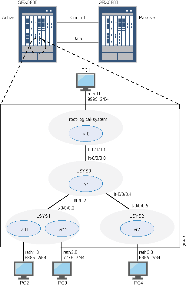
Topology
Figure 2 shows the topology used in this example.
Configuration
- Chassis Cluster Configuration with IPv6 Addresses (Primary Administrator)
- Logical System Configuration with IPv6 Addresses (Primary Administrator)
- User Logical System Configuration with IPv6 (User Logical System Administrator)
Chassis Cluster Configuration with IPv6 Addresses (Primary Administrator)
CLI Quick Configuration
To quickly create logical systems and user
logical system administrators and configure the primary and interconnect
logical systems, copy the following commands, paste them into a text
file, remove any line breaks, change any details necessary to match
your network configuration, and then copy and paste the commands into
the CLI at the [edit] hierarchy level.
On {primary:node0}
set chassis cluster control-ports fpc 0 port 0
set chassis cluster control-ports fpc 6 port 0
set interfaces fab0 fabric-options member-interfaces ge-1/1/0
set interfaces fab1 fabric-options member-interfaces ge-7/1/0
set groups node0 system host-name SRX5800-1
set groups node0 interfaces fxp0 unit 0 family inet address 10.157.90.24/9
set groups node0 system backup-router 10.157.64.1 destination 0.0.0.0/0
set groups node1 system host-name SRX5800-2
set groups node1 interfaces fxp0 unit 0 family inet address 10.157.90.23/19
set groups node1 system backup-router 10.157.64.1 destination 0.0.0.0/0
set apply-groups “${node}”
set chassis cluster reth-count 5
set chassis cluster redundancy-group 0 node 0 priority 200
set chassis cluster redundancy-group 0 node 1 priority 100
set chassis cluster redundancy-group 1 node 0 priority 200
set chassis cluster redundancy-group 1 node 1 priority 100
set interfaces ge-1/0/0 gigether-options redundant-parent reth0
set interfaces ge-1/0/1 gigether-options redundant-parent reth1
set interfaces ge-1/0/2 gigether-options redundant-parent reth2
set interfaces ge-1/0/3 gigether-options redundant-parent reth3
set interfaces ge-7/0/0 gigether-options redundant-parent reth0
set interfaces ge-7/0/1 gigether-options redundant-parent reth1
set interfaces ge-7/0/2 gigether-options redundant-parent reth2
set interfaces ge-7/0/3 gigether-options redundant-parent reth3
set interfaces reth0 redundant-ether-options redundancy-group 1
set interfaces reth0 unit 0 family inet6 address 9995::1/64
set interfaces reth1 redundant-ether-options redundancy-group 1
set interfaces reth2 redundant-ether-options redundancy-group 1
set interfaces reth3 redundant-ether-options redundancy-group 1
Step-by-Step Procedure
The following example requires you to navigate various levels in the configuration hierarchy. For instructions on how to do that, see Using the CLI Editor in Configuration Mode in the Junos OS CLI User Guide.
To configure a chassis cluster:
Perform the following steps on the primary device (node
0). They are automatically copied over to the secondary device (node
1) when you execute a commit command.
-
Configure control ports for the clusters.
[edit chassis cluster] user@host# set control-ports fpc 0 port 0 user@host# set control-ports fpc 6 port 0
-
Configure the fabric (data) ports of the cluster that are used to pass RTOs in active/passive mode.
[edit interfaces] user@host# set fab0 fabric-options member-interfaces ge-1/1/0 user@host# set fab1 fabric-options member-interfaces ge-7/1/0
-
Assign some elements of the configuration to a specific member. Configure out-of-band management on the fxp0 interface of the SRX Services Gateway using separate IP addresses for the individual control planes of the cluster.
[edit] user@host# set groups node0 system host-name SRX5800-1 user@host# set groups node0 interfaces fxp0 unit 0 family inet address 10.157.90.24/9 user@host# set groups node0 system backup-router 10.157.64.1 destination 0.0.0.0/0 user@host# set groups node1 system host-name SRX5800-2 user@host# set groups node1 interfaces fxp0 unit 0 family inet address 10.157.90.23/19 user@host# set groups node1 system backup-router 10.157.64.1 destination 0.0.0.0/0 user@host# set apply-groups “${node}” -
Configure redundancy groups for chassis clustering.
[edit chassis cluster] user@host# set reth-count 5 user@host# set redundancy-group 0 node 0 priority 200 user@host# set redundancy-group 0 node 1 priority 100 user@host# set redundancy-group 1 node 0 priority 200 user@host# set redundancy-group 1 node 1 priority 100
-
Configure the data interfaces on the platform so that in the event of a data plane failover, the other chassis cluster member can take over the connection seamlessly.
[edit interfaces] user@host# set ge-1/0/0 gigether-options redundant-parent reth0 user@host# set ge-1/0/1 gigether-options redundant-parent reth1 user@host# set ge-1/0/2 gigether-options redundant-parent reth2 user@host# set ge-1/0/3 gigether-options redundant-parent reth3 user@host# set ge-7/0/0 gigether-options redundant-parent reth0 user@host# set ge-7/0/1 gigether-options redundant-parent reth1 user@host# set ge-7/0/2 gigether-options redundant-parent reth2 user@host# set ge-7/0/3 gigether-options redundant-parent reth3 user@host# set reth0 redundant-ether-options redundancy-group 1 user@host# set reth0 unit 0 family inet6 address 9995::1/64 user@host# set reth1 redundant-ether-options redundancy-group 1 user@host# set reth2 redundant-ether-options redundancy-group 1 user@host# set reth3 redundant-ether-options redundancy-group 1
Results
From operational mode, confirm your configuration by
entering the show configuration command. If the output
does not display the intended configuration, repeat the configuration
instructions in this example to correct it.
user@host> show configuration
version ;
groups {
node0 {
system {
host-name SRX58001;
backup-router 10.157.64.1 destination 0.0.0.0/0;
}
interfaces {
fxp0 {
unit 0 {
family inet {
address 10.157.90.24/9;
}
}
}
}
}
node1 {
system {
host-name SRX58002;
backup-router 10.157.64.1 destination 0.0.0.0/0;
}
interfaces {
fxp0 {
unit 0 {
family inet {
address 10.157.90.23/19;
}
}
}
}
}
}
apply-groups "${node}";
chassis {
cluster {
control-link-recovery;
reth-count 5;
control-ports {
fpc 0 port 0;
fpc 6 port 0;
}
redundancy-group 0 {
node 0 priority 200;
node 1 priority 100;
}
redundancy-group 1 {
node 0 priority 200;
node 1 priority 100;
}
}
}
interfaces {
ge-1/0/0 {
gigether–options {
redundant–parent reth0;
}
}
ge-1/0/1 {
gigether–options {
redundant–parent reth1;
}
}
ge-1/0/2 {
gigether–options {
redundant–parent reth2;
}
}
ge-1/0/3 {
gigether–options {
redundant–parent reth3;
}
}
ge-7/0/0 {
gigether–options {
redundant–parent reth0;
}
}
ge-7/0/1 {
gigether–options {
redundant–parent reth1;
}
}
ge-7/0/2 {
gigether–options {
redundant–parent reth2;
}
}
ge-7/0/3 {
gigether–options {
redundant–parent reth3;
}
}
fab0 {
fabric–options {
member–interfaces {
ge-1/1/0;
}
}
}
fab1 {
fabric–options {
member–interfaces {
ge-7/1/0;
}
}
}
reth0 {
redundant–ether–options {
redundancy–group 1;
}
unit 0 {
family inet6 {
address 9995::1/64;
}
}
}
reth1 {
redundant–ether–options {
redundancy–group 1;
}
}
reth2 {
redundant–ether–options {
redundancy–group 1;
}
}
reth3 {
redundant–ether–options {
redundancy–group 1;
}
}
}Logical System Configuration with IPv6 Addresses (Primary Administrator)
CLI Quick Configuration
To quickly create logical systems and user
logical system administrators and configure the primary and interconnect
logical systems, copy the following commands, paste them into a text
file, remove any line breaks, change any details necessary to match
your network configuration, and then copy and paste the commands into
the CLI at the [edit] hierarchy level.
You are prompted to enter and then reenter plain-text passwords.
On {primary:node0}
set logical-systems LSYS1 set logical-systems LSYS2 set logical-systems LSYS0 set system login class lsys1 logical-system LSYS1 set system login class lsys1 permissions all set system login user lsys1admin full-name lsys1-admin set system login user lsys1admin class lsys1 set user lsys1admin authentication plain-text-password set system login class lsys2 logical-system LSYS2 set system login class lsys2 permissions all set system login user lsys2admin full-name lsys2-admin set system login user lsys2admin class lsys2 set system login user lsys2admin authentication plain-text-password set system security-profile SP-root policy maximum 200 set system security-profile SP-root policy reserved 100 set system security-profile SP-root zone maximum 200 set system security-profile SP-root zone reserved 100 set system security-profile SP-root flow-session maximum 200 set system security-profile SP-root flow-session reserved 100 set system security-profile SP-root root-logical-system set system security-profile SP0 logical-system LSYS0 set system security-profile SP1 policy maximum 100 set system security-profile SP1 policy reserved 50 set system security-profile SP1 zone maximum 100 set system security-profile SP1 zone reserved 50 set system security-profile SP1 flow-session maximum 100 set system security-profile SP1 flow-session reserved 50 set system security-profile SP1 logical-system LSYS1 set system security-profile SP2 policy maximum 100 set system security-profile SP2 policy reserved 50 set system security-profile SP2 zone maximum 100 set system security-profile SP2 zone reserved 50 set system security-profile SP2 flow-session maximum 100 set system security-profile SP2 flow-session reserved 50 set system security-profile SP2 logical-system LSYS2 set interfaces lt-0/0/0 unit 1 encapsulation ethernet set interfaces lt-0/0/0 unit 1 peer-unit 0 set interfaces lt-0/0/0 unit 1 family inet6 address 2111::1/64 set routing-instances vr0 instance-type virtual-router set routing-instances vr0 interface lt-0/0/0.1 set routing-instances vr0 interface reth0.0 set routing-instances vr0 routing-options rib vr0.inet6.0 static route 8885::/64 next-hop 2111::3 set routing-instances vr0 routing-options rib vr0.inet6.0 static route 7775::/64 next-hop 2111::3 set routing-instances vr0 routing-options rib vr0.inet6.0 static route 6665::/64 next-hop 2111::5 set security zones security-zone root-trust host-inbound-traffic system-services all set security zones security-zone root-trust host-inbound-traffic protocols all set security zones security-zone root-trust interfaces reth0.0 set security zones security-zone root-untrust host-inbound-traffic system-services all set security zones security-zone root-untrust host-inbound-traffic protocols all set security zones security-zone root-untrust interfaces lt-0/0/0.1 set security policies from-zone root-trust to-zone root-untrust policy root-Trust_to_root-Untrust match source-address any set security policies from-zone root-trust to-zone root-untrust policy root-Trust_to_root-Untrust match destination-address any set security policies from-zone root-trust to-zone root-untrust policy root-Trust_to_root-Untrust match application any set security policies from-zone root-trust to-zone root-untrust policy root-Trust_to_root-Untrust then permit set security policies from-zone root-untrust to-zone root-trust policy root-Untrust_to_root-Trust match source-address any set security policies from-zone root-untrust to-zone root-trust policy root-Untrust_to_root-Trust match destination-address any set security policies from-zone root-untrust to-zone root-trust policy root-Untrust_to_root-Trust match application any set security policies from-zone root-untrust to-zone root-trust policy root-Untrust_to_root-Trust then permit set security policies from-zone root-untrust to-zone root-untrust policy root-Untrust_to_root-Untrust match source-address any set security policies from-zone root-untrust to-zone root-untrust policy root-Untrust_to_root-Untrust match destination-address any set security policies from-zone root-untrust to-zone root-untrust policy root-Untrust_to_root-Untrust match application any set security policies from-zone root-untrust to-zone root-untrust policy root-Untrust_to_root-Untrust then permit set security policies from-zone root-trust to-zone root-trust policy root-Trust_to_root-Trust match source-address any set security policies from-zone root-trust to-zone root-trust policy root-Trust_to_root-Trust match destination-address any set security policies from-zone root-trust to-zone root-trust policy root-Trust_to_root-Trust match application any set security policies from-zone root-trust to-zone root-trust policy root-Trust_to_root-Trust then permit set logical-systems LSYS0 interfaces lt-0/0/0 unit 0 encapsulation ethernet-vpls set logical-systems LSYS0 interfaces lt-0/0/0 unit 0 peer-unit 1 set logical-systems LSYS0 interfaces lt-0/0/0 unit 2 encapsulation ethernet-vpls set logical-systems LSYS0 interfaces lt-0/0/0 unit 2 peer-unit 3 set logical-systems LSYS0 interfaces lt-0/0/0 unit 4 encapsulation ethernet-vpls set logical-systems LSYS0 interfaces lt-0/0/0 unit 4 peer-unit 5 set logical-systems LSYS0 routing-instances vr instance-type vpls set logical-systems LSYS0 routing-instances vr interface lt-0/0/0.0 set logical-systems LSYS0 routing-instances vr interface lt-0/0/0.2 set logical-systems LSYS0 routing-instances vr interface lt-0/0/0.4 set logical-systems LSYS1 interfaces lt-0/0/0 unit 3 encapsulation ethernet set logical-systems LSYS1 interfaces lt-0/0/0 unit 3 peer-unit 2 set logical-systems LSYS1 interfaces lt-0/0/0 unit 3 family inet6 address 2111::3/64 set logical-systems LSYS2 interfaces lt-0/0/0 unit 5 encapsulation ethernet set logical-systems LSYS2 interfaces lt-0/0/0 unit 5 peer-unit 4 set logical-systems LSYS2 interfaces lt-0/0/0 unit 5 family inet6 address 2111::5/64
Step-by-Step Procedure
The following example requires you to navigate various levels in the configuration hierarchy. For instructions on how to do that, see Using the CLI Editor in Configuration Mode.
To create logical systems and user logical system administrators and configure the primary and interconnect logical systems:
-
Create the interconnect and user logical systems.
[edit logical-systems] user@host# set LSYS0 user@host# set LSYS1 user@host# set LSYS2
-
Configure user logical system administrators.
Step-by-Step Procedure
-
Configure the user logical system administrator for LSYS1.
[edit system login] user@host# set class lsys1 logical-system LSYS1 user@host# set class lsys1 permissions all user@host# set user lsys1admin full-name lsys1-admin user@host# set user lsys1admin class lsys1 user@host# set user lsys1admin authentication plain-text-password
-
Configure the user logical system administrator for LSYS2.
[edit system login] user@host# set class lsys2 logical-system LSYS2 user@host# set class lsys2 permissions all user@host# set user lsys2admin full-name lsys2-admin user@host# set user lsys2admin class lsys2 user@host# set user lsys2admin authentication plain-text-password
-
-
Configure security profiles and assign them to logical systems.
Step-by-Step Procedure
-
Configure a security profile and assign it to the root logical system.
[edit system security-profile] user@host# set SP-root policy maximum 200 user@host# set SP-root policy reserved 100 user@host# set SP-root zone maximum 200 user@host# set SP-root zone reserved 100 user@host# set SP-root flow-session maximum 200 user@host# set SP-root flow-session reserved 100 user@host# set SP-root root-logical-system
-
Assign a dummy security profile containing no resources to the interconnect logical system LSYS0.
[edit system security-profile] user@host# set SP0 logical-system LSYS0 -
Configure a security profile and assign it to LSYS1.
[edit system security-profile] user@host# set SP1 policy maximum 100 user@host# set SP1 policy reserved 50 user@host# set SP1 zone maximum 100 user@host# set SP1 zone reserved 50 user@host# set SP1 flow-session maximum 100 user@host# set SP1 flow-session reserved 50 user@host# set SP1 logical-system LSYS1
-
Configure a security profile and assign it to LSYS2.
[edit system security-profile] user@host# set SP2 policy maximum 100 user@host# set SP2 policy reserved 50 user@host# set SP2 zone maximum 100 user@host# set SP2 zone reserved 50 user@host# set SP2 flow-session maximum 100 user@host# set SP2 flow-session reserved 50 user@host# set SP2 logical-system LSYS2
-
-
Configure the primary logical system.
Step-by-Step Procedure
-
Configure logical tunnel interfaces.
[edit interfaces] user@host# set lt-0/0/0 unit 1 encapsulation ethernet user@host# set lt-0/0/0 unit 1 peer-unit 0 user@host# set lt-0/0/0 unit 1 family inet6 address 2111::1/64
-
Configure a routing instance.
[edit routing-instances] user@host# set vr0 instance-type virtual-router user@host# set vr0 interface lt-0/0/0.1 user@host# set vr0 interface reth0.0 user@host# set vr0 routing-options rib vr0.inet6.0 static route 8885::/64 next-hop 2111::3 user@host# set vr0 routing-options rib vr0.inet6.0 static route 7775::/64 next-hop 2111::3 user@host# set vr0 routing-options rib vr0.inet6.0 static route 6665::/64 next-hop 2111::5
-
Configure zones.
[edit security zones] user@host# set security-zone root-trust host-inbound-traffic system-services all user@host# set security-zone root-trust host-inbound-traffic protocols all user@host# set security-zone root-trust interfaces reth0.0 user@host# set security-zone root-untrust host-inbound-traffic system-services all user@host# set security-zone root-untrust host-inbound-traffic protocols all user@host# set security-zone root-untrust interfaces lt-0/0/0.1
-
Configure security policies.
[edit security policies from-zone root-trust to-zone root-untrust] user@host# set policy root-Trust_to_root-Untrust match source-address any user@host# set policy root-Trust_to_root-Untrust match destination-address any user@host# set policy root-Trust_to_root-Untrust match application any user@host# set policy root-Trust_to_root-Untrust then permit
[edit security policies from-zone root-untrust to-zone root-trust] user@host# set policy root-Untrust_to_root-Trust match source-address any user@host# set policy root-Untrust_to_root-Trust match destination-address any user@host# set policy root-Untrust_to_root-Trust match application any user@host# set policy root-Untrust_to_root-Trust then permit
[edit security policies from-zone root-untrust to-zone root-untrust] user@host# set policy root-Untrust_to_root-Untrust match source-address any user@host# set policy root-Untrust_to_root-Untrust match destination-address any user@host# set policy root-Untrust_to_root-Untrust match application any user@host# set policy root-Untrust_to_root-Untrust then permit
[edit security policies from-zone root-trust to-zone root-trust] user@host# set policy root-Trust_to_root-Trust match source-address any user@host# set policy root-Trust_to_root-Trust match destination-address any user@host# set policy root-Trust_to_root-Trust match application any user@host# set policy root-Trust_to_root-Trust then permit
-
-
Configure the interconnect logical system.
Step-by-Step Procedure
-
Configure logical tunnel interfaces.
[edit logical-systems LSYS0 interfaces] user@host# set lt-0/0/0 unit 0 encapsulation ethernet-vpls user@host# set lt-0/0/0 unit 0 peer-unit 1 user@host# set lt-0/0/0 unit 2 encapsulation ethernet-vpls user@host# set lt-0/0/0 unit 2 peer-unit 3 user@host# set lt-0/0/0 unit 4 encapsulation ethernet-vpls user@host# set lt-0/0/0 unit 4 peer-unit 5
-
Configure the VPLS routing instance.
[edit logical-systems LSYS0 routing-instances] user@host# set vr instance-type vpls user@host# set vr interface lt-0/0/0.0 user@host# set vr interface lt-0/0/0.2 user@host# set vr interface lt-0/0/0.4
-
-
Configure logical tunnel interfaces for the user logical systems.
Step-by-Step Procedure
-
Configure logical tunnel interfaces for LSYS1.
[edit logical-systems LSYS1 interfaces ] user@host# set lt-0/0/0 unit 3 encapsulation ethernet user@host# set lt-0/0/0 unit 3 peer-unit 2 user@host# set lt-0/0/0 unit 3 family inet6 address 2111::3/64
-
Configure logical tunnel interfaces for LSYS2.
[edit logical-systems LSYS2 interfaces ] user@host# set lt-0/0/0 unit 5 encapsulation ethernet user@host# set lt-0/0/0 unit 5 peer-unit 4 user@host# set lt-0/0/0 unit 5 family inet6 address 2111::5/64
-
Results
From configuration mode, confirm the configuration
for LSYS0 by entering the show logical-systems LSYS0 command.
If the output does not display the intended configuration, repeat
the configuration instructions in this example to correct it.
[edit]
user@host# show logical-systems LSYS0
interfaces {
lt-0/0/0 {
unit 0 {
encapsulation ethernet-vpls;
peer-unit 1;
}
unit 2 {
encapsulation ethernet-vpls;
peer-unit 3;
}
unit 4 {
encapsulation ethernet-vpls;
peer-unit 5;
}
}
}
routing-instances {
vr {
instance-type vpls;
interface lt-0/0/0.0;
interface lt-0/0/0.2;
interface lt-0/0/0.4;
}
}
From configuration mode, confirm the configuration for the primary
logical system by entering the show interfaces, show routing-instances, and show security commands. If
the output does not display the intended configuration, repeat the
configuration instructions in this example to correct it.
[edit]
user@host# show interfaces
lt-0/0/0 {
unit 1 {
encapsulation ethernet;
peer-unit 0;
family inet6 {
address 2111::1/64;
}
}
}
ge-1/0/0 {
gigether-options {
redundant-parent reth0;
}
}
ge-1/0/1 {
gigether-options {
redundant-parent reth1;
}
}
ge-1/0/2 {
gigether-options {
redundant-parent reth2;
}
}
ge-1/0/3 {
gigether-options {
redundant-parent reth3;
}
}
ge-7/0/0 {
gigether-options {
redundant-parent reth0;
}
}
ge-7/0/1 {
gigether-options {
redundant-parent reth1;
}
}
ge-7/0/2 {
gigether-options {
redundant-parent reth2;
}
}
ge-7/0/3 {
gigether-options {
redundant-parent reth3;
}
}
fab0 {
fabric-options {
member-interfaces {
ge-1/1/0;
}
}
}
fab1 {
fabric-options {
member-interfaces {
ge-7/1/0;
}
}
}
reth0 {
redundant-ether-options {
redundancy-group 1;
}
unit 0 {
family inet6 {
address 9995::1/64;
}
}
}
reth1 {
redundant-ether-options {
redundancy-group 1;
}
}
reth2 {
redundant-ether-options {
redundancy-group 1;
}
}
reth3 {
redundant-ether-options {
redundancy-group 1;
}
}
[edit]
user@host# show routing-instances
vr0 {
instance-type virtual-router;
interface lt-0/0/0.1;
interface reth0.0;
routing-options {
rib vr0.inet6.0 {
static {
route 8885::/64 next-hop 2111::3;
route 7775::/64 next-hop 2111::3;
route 6665::/64 next-hop 2111::5;
}
}
}
}
[edit]
user@host# show security
policies {
from-zone root-trust to-zone root-untrust {
policy root-Trust_to_root-Untrust {
match {
source-address any;
destination-address any;
application any;
}
then {
permit;
}
}
}
from-zone root-untrust to-zone root-trust {
policy root-Untrust_to_root-Trust {
match {
source-address any;
destination-address any;
application any;
}
then {
permit;
}
}
}
from-zone root-untrust to-zone root-untrust {
policy root-Untrust_to_root-Untrust {
match {
source-address any;
destination-address any;
application any;
}
then {
permit;
}
}
}
from-zone root-trust to-zone root-trust {
policy root-Trust_to_root-Trust {
match {
source-address any;
destination-address any;
application any;
}
then {
permit;
}
}
}
}
zones {
security-zone root-trust {
host-inbound-traffic {
system-services {
all;
}
protocols {
all;
}
}
interfaces {
reth0.0;
}
}
security-zone root-untrust {
host-inbound-traffic {
system-services {
all;
}
protocols {
all;
}
}
interfaces {
lt-0/0/0.1;
}
}
}
If you are done configuring the device, enter commit from configuration mode.
User Logical System Configuration with IPv6 (User Logical System Administrator)
CLI Quick Configuration
To quickly configure user logical systems,
copy the following commands, paste them into a text file, remove any
line breaks, change any details necessary to match your network configuration,
and then copy and paste the commands into the CLI at the [edit] hierarchy level.
Enter the following commands while logged in as the user logical system administrator for LSYS1:
set interfaces reth1 unit 0 family inet6 address 8885::1/64 set interfaces reth2 unit 0 family inet6 address 7775::1/64 set routing-instances vr11 instance-type virtual-router set routing-instances vr11 interface lt-0/0/0.3 set routing-instances vr11 interface reth1.0 set routing-instances vr11 routing-options rib vr11.inet6.0 static route 6665::/64 next-hop 2111::5 set routing-instances vr11 routing-options rib vr11.inet6.0 static route 9995::/64 next-hop 2111::1 set routing-instances vr12 instance-type virtual-router set routing-instances vr12 interface reth2.0 set routing-instances vr12 routing-options interface-routes rib-group inet6 vr11vr12v6 set routing-instances vr12 rrouting-options rib vr12.inet6.0 static route 8885::/64 next-table vr11.inet6.0 set routing-instances vr12 routing-options rib vr12.inet6.0 static route 9995::/64 next-table vr11.inet6.0 set routing-instances vr12 routing-options rib vr12.inet6.0 static route 6665::/64 next-table vr11.inet6.0 set routing-instances vr12 routing-options rib vr12.inet6.0 static route 2111::/64 next-table vr11.inet6.0 set routing-options rib-groups vr11vr12v6 import-rib vr11.inet6.0 set routing-options rib-groups vr11vr12v6 import-rib vr12.inet6.0 set security zones security-zone lsys1-trust host-inbound-traffic system-services all set security zones security-zone lsys1-trust host-inbound-traffic protocols all set security zones security-zone lsys1-trust interfaces reth1.0 set security zones security-zone lsys1-trust interfaces lt-0/0/0.3 set security zones security-zone lsys1-untrust host-inbound-traffic system-services all set security zones security-zone lsys1-untrust host-inbound-traffic protocols all set security zones security-zone lsys1-untrust interfaces reth2.0 set security policies from-zone lsys1-trust to-zone lsys1-untrust policy lsys1trust-to-lsys1untrust match source-address any set security policies from-zone lsys1-trust to-zone lsys1-untrust policy lsys1trust-to-lsys1untrust match destination-address any set security policies from-zone lsys1-trust to-zone lsys1-untrust policy lsys1trust-to-lsys1untrust match application any set security policies from-zone lsys1-trust to-zone lsys1-untrust policy lsys1trust-to-lsys1untrust then permit set security policies from-zone lsys1-untrust to-zone lsys1-trust policy lsys1untrust-to-lsys1trust match source-address any set security policies from-zone lsys1-untrust to-zone lsys1-trust policy lsys1untrust-to-lsys1trust match destination-address any set security policies from-zone lsys1-untrust to-zone lsys1-trust policy lsys1untrust-to-lsys1trust match application any set security policies from-zone lsys1-untrust to-zone lsys1-trust policy lsys1untrust-to-lsys1trust then permit set security policies from-zone lsys1-untrust to-zone lsys1-untrust policy lsys1untrust-to-lsys1untrust match source-address any set security policies from-zone lsys1-untrust to-zone lsys1-untrust policy lsys1untrust-to-lsys1untrust match destination-address any set security policies from-zone lsys1-untrust to-zone lsys1-untrust policy lsys1untrust-to-lsys1untrust match application any set security policies from-zone lsys1-untrust to-zone lsys1-untrust policy lsys1untrust-to-lsys1untrust then permit set security policies from-zone lsys1-trust to-zone lsys1-trust policy lsys1trust-to-lsys1trust match source-address any set security policies from-zone lsys1-trust to-zone lsys1-trust policy lsys1trust-to-lsys1trust match destination-address any set security policies from-zone lsys1-trust to-zone lsys1-trust policy lsys1trust-to-lsys1trust match application any set security policies from-zone lsys1-trust to-zone lsys1-trust policy lsys1trust-to-lsys1trust then permit
Enter the following commands while logged in as the user logical system administrator for LSYS2:
set interfaces reth3 unit 0 family inet6 address 6665::1/64 set routing-instances vr2 instance-type virtual-router set routing-instances vr2 interface lt-0/0/0.5 set routing-instances vr2 interface reth3.0 set routing-instances vr2 routing-options rib vr2.inet6.0 static route 7775::/64 next-hop 2111::3 set routing-instances vr2 routing-options rib vr2.inet6.0 static route 8885::/64 next-hop 2111::3 set routing-instances vr2 routing-options rib vr2.inet6.0 static route 9995::/64 next-hop 2111::1 set security zones security-zone lsys2-trust host-inbound-traffic system-services all set security zones security-zone lsys2-trust host-inbound-traffic protocols all set security zones security-zone lsys2-trust interfaces reth3.0 set security zones security-zone lsys2-untrust host-inbound-traffic system-services all set security zones security-zone lsys2-untrust host-inbound-traffic protocols all set security zones security-zone lsys2-untrust interfaces lt-0/0/0.5 set security policies from-zone lsys2-trust to-zone lsys2-untrust policy lsys2trust-to-lsys2untrust match source-address any set security policies from-zone lsys2-trust to-zone lsys2-untrust policy lsys2trust-to-lsys2untrust match destination-address any set security policies from-zone lsys2-trust to-zone lsys2-untrust policy lsys2trust-to-lsys2untrust match application any set security policies from-zone lsys2-trust to-zone lsys2-untrust policy lsys2trust-to-lsys2untrust then permit set security policies from-zone lsys2-untrust to-zone lsys2-trust policy lsys2untrust-to-lsys2trust match source-address any set security policies from-zone lsys2-untrust to-zone lsys2-trust policy lsys2untrust-to-lsys2trust match destination-address any set security policies from-zone lsys2-untrust to-zone lsys2-trust policy lsys2untrust-to-lsys2trust match application any set security policies from-zone lsys2-untrust to-zone lsys2-trust policy lsys2untrust-to-lsys2trust then permit set security policies from-zone lsys2-untrust to-zone lsys2-untrust policy lsys2untrust-to-lsys2untrust match source-address any set security policies from-zone lsys2-untrust to-zone lsys2-untrust policy lsys2untrust-to-lsys2untrust match destination-address any set security policies from-zone lsys2-untrust to-zone lsys2-untrust policy lsys2untrust-to-lsys2untrust match application any set security policies from-zone lsys2-untrust to-zone lsys2-untrust policy lsys2untrust-to-lsys2untrust then permit set security policies from-zone lsys2-trust to-zone lsys2-trust policy lsys2trust-to-lsys2trust match source-address any set security policies from-zone lsys2-trust to-zone lsys2-trust policy lsys2trust-to-lsys2trust match destination-address any set security policies from-zone lsys2-trust to-zone lsys2-trust policy lsys2trust-to-lsys2trust match application any set security policies from-zone lsys2-trust to-zone lsys2-trust policy lsys2trust-to-lsys2trust then permit
Step-by-Step Procedure
The user logical system administrator performs the following
configuration while logged in to his or her user logical system. The
primary administrator can also configure a user logical system at
the [edit logical-systems logical-system] hierarchy level.
The following example requires you to navigate various levels in the configuration hierarchy. For instructions on how to do that, see Using the CLI Editor in Configuration Mode.
To configure the LSYS1 user logical system:
-
Configure interfaces.
[edit interfaces] lsys1-admin@host:LSYS1# set reth1 unit 0 family inet6 address 8885::1/64 lsys1-admin@host:LSYS1# set reth2 unit 0 family inet6 address 7775::1/64
-
Configure routing.
[edit routing-instances] lsys1-admin@host:LSYS1# set vr11 instance-type virtual-router lsys1-admin@host:LSYS1# set vr11 interface lt-0/0/0.3 lsys1-admin@host:LSYS1# set vr11 interface reth1.0 lsys1-admin@host:LSYS1# set vr11 routing-options rib vr11.inet6.0 static route 6665::/64 next-hop 2111::5 lsys1-admin@host:LSYS1# set vr11 routing-options rib vr11.inet6.0 static route 9995::/64 next-hop 2111::1 lsys1-admin@host:LSYS1# set vr12 instance-type virtual-router lsys1-admin@host:LSYS1# set vr12 interface reth2.0 lsys1-admin@host:LSYS1# set vr12 routing-options interface-routes rib-group inet6 vr11vr12v6 lsys1-admin@host:LSYS1# set vr12 routing-options rib vr12.inet6.0 static route 8885::/64 next-table vr11.inet6.0 lsys1-admin@host:LSYS1# set vr12 routing-options rib vr12.inet6.0 static route 9995::/64 next-table vr11.inet6.0 lsys1-admin@host:LSYS1# set vr12 routing-options rib vr12.inet6.0 static route 6665::/64 next-table vr11.inet6.0 lsys1-admin@host:LSYS1# set vr12 routing-options rib vr12.inet6.0 static route 2111::/64 next-table vr11.inet6.0
[edit routing-options] lsys1-admin@host:LSYS1# set rib-groups vr11vr12v6 import-rib vr11.inet6.0 lsys1-admin@host:LSYS1# set rib-groups vr11vr12v6 import-rib vr12.inet6.0
-
Configure zones and security policies.
[edit security zones] lsys1-admin@host:LSYS1# set security-zone lsys1-trust host-inbound-traffic system-services all lsys1-admin@host:LSYS1# set security-zone lsys1-trust host-inbound-traffic protocols all lsys1-admin@host:LSYS1# set security-zone lsys1-trust interfaces reth1.0 lsys1-admin@host:LSYS1# set security-zone lsys1-trust interfaces lt-0/0/0.3 lsys1-admin@host:LSYS1# set security-zone lsys1-untrust host-inbound-traffic system-services all lsys1-admin@host:LSYS1# set security-zone lsys1-untrust host-inbound-traffic protocols all lsys1-admin@host:LSYS1# set security-zone lsys1-untrust interfaces reth2.0
[edit security policies from-zone lsys1-trust to-zone lsys1-untrust] lsys1-admin@host:LSYS1# set policy lsys1trust-to-lsys1untrust match source-address any lsys1-admin@host:LSYS1# set policy lsys1trust-to-lsys1untrust match destination-address any lsys1-admin@host:LSYS1# set policy lsys1trust-to-lsys1untrust match application any lsys1-admin@host:LSYS1# set policy lsys1trust-to-lsys1untrust then permit
[edit security policies from-zone lsys1-untrust to-zone lsys1-trust] lsys1-admin@host:LSYS1# set policy lsys1untrust-to-lsys1trust match source-address any lsys1-admin@host:LSYS1# set policy lsys1untrust-to-lsys1trust match destination-address any lsys1-admin@host:LSYS1# set policy lsys1untrust-to-lsys1trust match application any lsys1-admin@host:LSYS1# set policy lsys1untrust-to-lsys1trust then permit
[edit security policies from-zone lsys1-untrust to-zone lsys1-untrust] lsys1-admin@host:LSYS1# set policy lsys1untrust-to-lsys1untrust match source-address any lsys1-admin@host:LSYS1# set policy lsys1untrust-to-lsys1untrust match destination-address any lsys1-admin@host:LSYS1# set policy lsys1untrust-to-lsys1untrust match application any lsys1-admin@host:LSYS1# set policy lsys1untrust-to-lsys1untrust then permit
[edit security policies from-zone lsys1-trust to-zone lsys1-trust] lsys1-admin@host:LSYS1# set policy lsys1trust-to-lsys1trust match source-address any lsys1-admin@host:LSYS1# set policy lsys1trust-to-lsys1trust match destination-address any lsys1-admin@host:LSYS1# set policy lsys1trust-to-lsys1trust match application any lsys1-admin@host:LSYS1# set policy lsys1trust-to-lsys1trust then permit
Step-by-Step Procedure
To configure the LSYS2 user logical system:
-
Configure interfaces.
[edit interfaces] lsys2-admin@host:LSYS2# set reth3 unit 0 family inet6 address 6665::1/64
-
Configure routing.
[edit routing-instances] lsys2-admin@host:LSYS2# set vr2 instance-type virtual-router lsys2-admin@host:LSYS2# set vr2 interface lt-0/0/0.5 lsys2-admin@host:LSYS2# set vr2 interface reth3.0 lsys2-admin@host:LSYS2# set vr2 routing-options rib vr2.inet6.0 static route 7775::/64 next-hop 2111::3 lsys2-admin@host:LSYS2# set vr2 routing-options rib vr2.inet6.0 static route 8885::/64 next-hop 2111::3 lsys2-admin@host:LSYS2# set vr2 routing-options rib vr2.inet6.0 static route 9995::/64 next-hop 2111::1
-
Configure zones and security policies.
[edit security zones] lsys2-admin@host:LSYS2# set security-zone lsys2-trust host-inbound-traffic system-services all lsys2-admin@host:LSYS2# set security-zone lsys2-trust host-inbound-traffic protocols all lsys2-admin@host:LSYS2# set security-zone lsys2-trust interfaces reth3.0 lsys2-admin@host:LSYS2# set security zones security-zone lsys2-untrust host-inbound-traffic system-services all lsys2-admin@host:LSYS2# set security-zone lsys2-untrust host-inbound-traffic protocols all lsys2-admin@host:LSYS2# set security-zone lsys2-untrust interfaces lt-0/0/0.5
[edit security policies from-zone lsys2-trust to-zone lsys2-untrust] lsys2-admin@host:LSYS2# set policy lsys2trust-to-lsys2untrust match source-address any lsys2-admin@host:LSYS2# set policy lsys2trust-to-lsys2untrust match destination-address any lsys2-admin@host:LSYS2# set policy lsys2trust-to-lsys2untrust match application any lsys2-admin@host:LSYS2# set policy lsys2trust-to-lsys2untrust then permit
[edit security policies from-zone from-zone lsys2-untrust to-zone lsys2-trust] lsys2-admin@host:LSYS2# set policy lsys2untrust-to-lsys2trust match source-address any lsys2-admin@host:LSYS2# set policy lsys2untrust-to-lsys2trust match destination-address any lsys2-admin@host:LSYS2# set policy lsys2untrust-to-lsys2trust match application any lsys2-admin@host:LSYS2# set policy lsys2untrust-to-lsys2trust then permit
[edit security policies from-zone lsys2-untrust to-zone lsys2-untrust] lsys2-admin@host:LSYS2# set policy lsys2untrust-to-lsys2untrust match source-address any lsys2-admin@host:LSYS2# set policy lsys2untrust-to-lsys2untrust match destination-address any lsys2-admin@host:LSYS2# set policy lsys2untrust-to-lsys2untrust match application any lsys2-admin@host:LSYS2# set policy lsys2untrust-to-lsys2untrust then permit
[edit security policies from-zone lsys2-trust to-zone lsys2-trust] lsys2-admin@host:LSYS2# set policy lsys2trust-to-lsys2trust match source-address any lsys2-admin@host:LSYS2# set policy lsys2trust-to-lsys2trust match destination-address any lsys2-admin@host:LSYS2# set policy lsys2trust-to-lsys2trust match application any lsys2-admin@host:LSYS2# set policy lsys2trust-to-lsys2trust then permit
Results
From configuration mode, confirm the configuration
for LSYS1 by entering the show interfaces, show routing-instances, show routing-options, and show security commands.
If the output does not display the intended configuration, repeat
the configuration instructions in this example to correct it.
[edit]
lsys1-admin@host:LSYS1# show interfaces
interfaces {
lt-0/0/0 {
unit 3 {
encapsulation ethernet;
peer-unit 2;
family inet6 {
address 2111::3/64;
}
}
}
reth1 {
unit 0 {
family inet6 {
address 8885::1/64;
}
}
}
reth2 {
unit 0 {
family inet6 {
address 7775::1/64;
}
}
}
}
[edit]
lsys1-admin@host:LSYS1# show routing-instances
routing-instances {
vr11 {
instance-type virtual-router;
interface lt-0/0/0.3;
interface reth1.0;
routing-options {
rib vr11.inet6.0 {
static {
route 6665::/64 next-hop 2111::5;
route 9995::/64 next-hop 2111::1;
}
}
}
}
vr12 {
instance-type virtual-router;
interface reth2.0;
routing-options {
interface-routes {
rib-group inet6 vr11vr12v6;
}
rib vr12.inet6.0 {
static {
route 8885::/64 next-table vr11.inet6.0;
route 9995::/64 next-table vr11.inet6.0;
route 6665::/64 next-table vr11.inet6.0;
route 2111::/64 next-table vr11.inet6.0;
}
}
}
}
}
[edit]
lsys1-admin@host:LSYS1# show routing-options
rib-groups {
vr11vr12v6 {
import-rib [ vr11.inet6.0 vr12.inet6.0 ];
}
}
[edit]
lsys1-admin@host:LSYS1# show security
security {
policies {
from-zone lsys1-trust to-zone lsys1-untrust {
policy lsys1trust-to-lsys1untrust {
match {
source-address any;
destination-address any;
application any;
}
then {
permit;
}
}
}
from-zone lsys1-untrust to-zone lsys1-trust {
policy lsys1untrust-to-lsys1trust {
match {
source-address any;
destination-address any;
application any;
}
then {
permit;
}
}
}
from-zone lsys1-untrust to-zone lsys1-untrust {
policy lsys1untrust-to-lsys1untrust {
match {
source-address any;
destination-address any;
application any;
}
then {
permit;
}
}
}
from-zone lsys1-trust to-zone lsys1-trust {
policy lsys1trust-to-lsys1trust {
match {
source-address any;
destination-address any;
application any;
}
then {
permit;
}
}
}
}
zones {
security-zone lsys1-trust {
host-inbound-traffic {
system-services {
all;
}
protocols {
all;
}
}
interfaces {
reth1.0;
lt-0/0/0.3;
}
}
security-zone lsys1-untrust {
host-inbound-traffic {
system-services {
all;
}
protocols {
all;
}
}
interfaces {
reth2.0;
}
}
}
}
From configuration mode, confirm the configuration for LSYS2
by entering the show interfaces, show routing-instances, and show security commands. If the output does not display
the intended configuration, repeat the configuration instructions
in this example to correct it.
[edit]
lsys2-admin@host:LSYS2# show interfaces
interfaces {
lt-0/0/0 {
unit 5 {
encapsulation ethernet;
peer-unit 4;
family inet6 {
address 2111::5/64;
}
}
}
reth3 {
unit 0 {
family inet6 {
address 6665::1/64;
}
}
}
}
[edit]
lsys2-admin@host:LSYS2# show routing-instances
routing-instances {
vr2 {
instance-type virtual-router;
interface lt-0/0/0.5;
interface reth3.0;
routing-options {
rib vr2.inet6.0 {
static {
route 7775::/64 next-hop 2111::3;
route 8885::/64 next-hop 2111::3;
route 9995::/64 next-hop 2111::1;
}
}
}
}
}
[edit]
lsys2-admin@host:LSYS2# show security
security {
policies {
from-zone lsys2-trust to-zone lsys2-untrust {
policy lsys2trust-to-lsys2untrust {
match {
source-address any;
destination-address any;
application any;
}
then {
permit;
}
}
}
from-zone lsys2-untrust to-zone lsys2-trust {
policy lsys2untrust-to-lsys2trust {
match {
source-address any;
destination-address any;
application any;
}
then {
permit;
}
}
}
from-zone lsys2-untrust to-zone lsys2-untrust {
policy lsys2untrust-to-lsys2untrust {
match {
source-address any;
destination-address any;
application any;
}
then {
permit;
}
}
}
from-zone lsys2-trust to-zone lsys2-trust {
policy lsys2trust-to-lsys2trust {
match {
source-address any;
destination-address any;
application any;
}
then {
permit;
}
}
}
}
zones {
security-zone lsys2-trust {
host-inbound-traffic {
system-services {
all;
}
protocols {
all;
}
}
interfaces {
reth3.0;
}
}
security-zone lsys2-untrust {
host-inbound-traffic {
system-services {
all;
}
protocols {
all;
}
}
interfaces {
lt-0/0/0.5;
}
}
}
}
If you are done configuring the device, enter commit from configuration mode.
Verification
Confirm that the configuration is working properly.
- Verifying Chassis Cluster Status (IPv6)
- Troubleshooting Chassis Cluster with Logs (IPv6)
- Verifying Logical System Licenses (IPv6)
- Verifying Logical System License Usage (IPv6)
- Verifying Intra-Logical System Traffic on a Logical System (IPv6)
- Verifying Intra-Logical System Traffic Within All Logical Systems (IPv6)
- Verifying Traffic Between User Logical Systems (IPv6)
Verifying Chassis Cluster Status (IPv6)
Purpose
Verify the chassis cluster status, failover status, and redundancy group information.
Action
From operational mode, enter the show chassis cluster
status command.
{primary:node0}
show chassis cluster status
Cluster ID: 1
Node                  Priority          Status    Preempt  Manual failover

Redundancy group: 0 , Failover count: 1
    node0                   200         primary        no       no
    node1                   100         secondary      no       no

Redundancy group: 1 , Failover count: 1
    node0                   200         primary        no       no
    node1                   100         secondary      no       no
Troubleshooting Chassis Cluster with Logs (IPv6)
Purpose
Use these logs to identify any chassis cluster issues. You should run these logs on both nodes.
Action
From operational mode, enter these show log commands.
user@host> show log jsrpd
user@host> show log chassisd
user@host> show log messages
user@host> show log dcd
user@host> show traceoptions
Verifying Logical System Licenses (IPv6)
Purpose
Verify information about logical system licenses.
Action
From operational mode, enter the show system license
status logical-system all command.
{primary:node0}
user@host> show system license status logical-system all
node0:
--------------------------------------------------------------------------
Logical system license status:

logical system name                 license status
root-logical-system                 enabled
LSYS0                               enabled
LSYS1                               enabled
LSYS2                               enabled
Verifying Logical System License Usage (IPv6)
Purpose
Verify information about logical system license usage.
The actual number of licenses used is only displayed on the primary node.
Action
From operational mode, enter the show system license command.
{primary:node0}
user@host> show system license
License usage:
                                 Licenses     Licenses    Licenses    Expiry
  Feature name                       used    installed      needed
  logical-system                        4           25           0    permanent

Licenses installed:
  License identifier: JUNOS305013
  License version: 2
  Valid for device: JN110B54BAGB
  Features:
    logical-system-25 - Logical System Capacity
      permanent
Verifying Intra-Logical System Traffic on a Logical System (IPv6)
Purpose
Verify information about currently active security sessions within a logical system.
Action
From operational mode, enter the show security
flow session logical-system LSYS1 command.
{primary:node0}
user@host> show security flow session logical-system LSYS1
node0:
--------------------------------------------------------------------------

Flow Sessions on FPC0 PIC1:

Session ID: 10000115, Policy name: lsys1trust-to-lsys1untrust/8, State: Active, Timeout: 1784, Valid
  In: 8885::2/34564 --> 7775::2/23;tcp, If: reth1.0, Pkts: 22, Bytes: 1745
  Out: 7775::2/23 --> 8885::2/34564;tcp, If: reth2.0, Pkts: 19, Bytes: 2108
Total sessions: 1

Flow Sessions on FPC2 PIC0:
Total sessions: 0

Flow Sessions on FPC2 PIC1:
Total sessions: 0

node1:
--------------------------------------------------------------------------

Flow Sessions on FPC0 PIC1:

Session ID: 10000006, Policy name: lsys1trust-to-lsys1untrust/8, State: Backup, Timeout: 14392, Valid
  In: 8885::2/34564 --> 7775::2/23;tcp, If: reth1.0, Pkts: 0, Bytes: 0
  Out: 7775::2/23 --> 8885::2/34564;tcp, If: reth2.0, Pkts: 0, Bytes: 0
Total sessions: 1

Flow Sessions on FPC2 PIC0:
Total sessions: 0

Flow Sessions on FPC2 PIC1:
Total sessions: 0
Verifying Intra-Logical System Traffic Within All Logical Systems (IPv6)
Purpose
Verify information about currently active security sessions on all logical systems.
Action
From operational mode, enter the show security
flow session logical-system all command.
{primary:node0}
user@host> show security flow session logical-system all
node0:
--------------------------------------------------------------------------

Flow Sessions on FPC0 PIC1:

Session ID: 10000115, Policy name: lsys1trust-to-lsys1untrust/8, State: Active, Timeout: 1776, Valid
Logical system: LSYS1
  In: 8885::2/34564 --> 7775::2/23;tcp, If: reth1.0, Pkts: 22, Bytes: 1745
  Out: 7775::2/23 --> 8885::2/34564;tcp, If: reth2.0, Pkts: 19, Bytes: 2108
Total sessions: 1

Flow Sessions on FPC2 PIC0:
Total sessions: 0

Flow Sessions on FPC2 PIC1:
Total sessions: 0

node1:
--------------------------------------------------------------------------

Flow Sessions on FPC0 PIC1:

Session ID: 10000006, Policy name: lsys1trust-to-lsys1untrust/8, State: Backup, Timeout: 14384, Valid
Logical system: LSYS1
  In: 8885::2/34564 --> 7775::2/23;tcp, If: reth1.0, Pkts: 0, Bytes: 0
  Out: 7775::2/23 --> 8885::2/34564;tcp, If: reth2.0, Pkts: 0, Bytes: 0
Total sessions: 1

Flow Sessions on FPC2 PIC0:
Total sessions: 0

Flow Sessions on FPC2 PIC1:
Total sessions: 0
Verifying Traffic Between User Logical Systems (IPv6)
Purpose
Verify information about currently active security sessions between logical systems.
Action
From operational mode, enter the show security
flow session logical-system logical-system-name
command.
{primary:node0}
user@host> show security flow session logical-system LSYS1

node0:
--------------------------------------------------------------------------

Flow Sessions on FPC0 PIC1:
Total sessions: 0

Flow Sessions on FPC2 PIC0:

Session ID: 80000118, Policy name: lsys1trust-to-lsys1trust/11, State: Active, Timeout: 1792, Valid
  In: 8885::2/34565 --> 6665::2/23;tcp, If: reth1.0, Pkts: 91, Bytes: 6802
  Out: 6665::2/23 --> 8885::2/34565;tcp, If: lt-0/0/0.3, Pkts: 65, Bytes: 6701
Total sessions: 1

Flow Sessions on FPC2 PIC1:
Total sessions: 0

node1:
--------------------------------------------------------------------------

Flow Sessions on FPC0 PIC1:
Total sessions: 0

Flow Sessions on FPC2 PIC0:

Session ID: 80000010, Policy name: lsys1trust-to-lsys1trust/11, State: Backup, Timeout: 14388, Valid
  In: 8885::2/34565 --> 6665::2/23;tcp, If: reth1.0, Pkts: 0, Bytes: 0
  Out: 6665::2/23 --> 8885::2/34565;tcp, If: lt-0/0/0.3, Pkts: 0, Bytes: 0
Total sessions: 1

Flow Sessions on FPC2 PIC1:
Total sessions: 0{primary:node0}
user@host> show security flow session logical-system LSYS2
node0:
--------------------------------------------------------------------------
Flow Sessions on FPC0 PIC1:
Total sessions: 0
Flow Sessions on FPC2 PIC0:
Session ID: 80000119, Policy name: lsys2untrust-to-lsys2trust/13, State: Active, Timeout: 1788, Valid
In: 8885::2/34565 --> 6665::2/23;tcp, If: lt-0/0/0.5, Pkts: 91, Bytes: 6802
Out: 6665::2/23 --> 8885::2/34565;tcp, If: reth3.0, Pkts: 65, Bytes: 6701
Total sessions: 1
Flow Sessions on FPC2 PIC1:
Total sessions: 0
node1:
--------------------------------------------------------------------------
Flow Sessions on FPC0 PIC1:
Total sessions: 0
Flow Sessions on FPC2 PIC0:
Session ID: 80000011, Policy name: lsys2untrust-to-lsys2trust/13, State: Backup, Timeout: 14380, Valid
In: 8885::2/34565 --> 6665::2/23;tcp, If: lt-0/0/0.5, Pkts: 0, Bytes: 0
Out: 6665::2/23 --> 8885::2/34565;tcp, If: reth3.0, Pkts: 0, Bytes: 0
Total sessions: 1
Flow Sessions on FPC2 PIC1:
Total sessions: 0
{primary:node0}
user@host> show security flow session logical-system all

node0:
--------------------------------------------------------------------------

Flow Sessions on FPC0 PIC1:
Total sessions: 0

Flow Sessions on FPC2 PIC0:

Session ID: 80000118, Policy name: lsys1trust-to-lsys1trust/11, State: Active, Timeout: 1784, Valid
Logical system: LSYS1
  In: 8885::2/34565 --> 6665::2/23;tcp, If: reth1.0, Pkts: 91, Bytes: 6802
  Out: 6665::2/23 --> 8885::2/34565;tcp, If: lt-0/0/0.3, Pkts: 65, Bytes: 6701

Session ID: 80000119, Policy name: lsys2untrust-to-lsys2trust/13, State: Active, Timeout: 1784, Valid
Logical system: LSYS2
  In: 8885::2/34565 --> 6665::2/23;tcp, If: lt-0/0/0.5, Pkts: 91, Bytes: 6802
  Out: 6665::2/23 --> 8885::2/34565;tcp, If: reth3.0, Pkts: 65, Bytes: 6701
Total sessions: 2

Flow Sessions on FPC2 PIC1:
Total sessions: 0

node1:
--------------------------------------------------------------------------

Flow Sessions on FPC0 PIC1:
Total sessions: 0

Flow Sessions on FPC2 PIC0:

Session ID: 80000010, Policy name: lsys1trust-to-lsys1trust/11, State: Backup, Timeout: 14378, Valid
Logical system: LSYS1
  In: 8885::2/34565 --> 6665::2/23;tcp, If: reth1.0, Pkts: 0, Bytes: 0
  Out: 6665::2/23 --> 8885::2/34565;tcp, If: lt-0/0/0.3, Pkts: 0, Bytes: 0

Session ID: 80000011, Policy name: lsys2untrust-to-lsys2trust/13, State: Backup, Timeout: 14376, Valid
Logical system: LSYS2
  In: 8885::2/34565 --> 6665::2/23;tcp, If: lt-0/0/0.5, Pkts: 0, Bytes: 0
  Out: 6665::2/23 --> 8885::2/34565;tcp, If: reth3.0, Pkts: 0, Bytes: 0
Total sessions: 2

Flow Sessions on FPC2 PIC1:
Total sessions: 0Change History Table
Feature support is determined by the platform and release you are using. Use Feature Explorer to determine if a feature is supported on your platform.
commit the configuration, a warning
message is displayed about the number of licenses required on backup
node as well, just as on primary node in all the previous releases.