Connecting Firewalls to Create a Chassis Cluster
A chassis cluster is created by physically connecting two identical cluster-supported Firewalls together using a pair of the same type of Ethernet connections. The connection is made for both a control link and a fabric (data) link between the two devices.
Control links in a chassis cluster are made using specific ports.
The interface value changes with the cluster offset value. Based on the cluster index, the interface is named as type-fpc/pic/port. For example, ge-1/0/1 , where 1 is cluster index and the FPC number. You must use the following ports to form the control link on the following Firewalls:
-
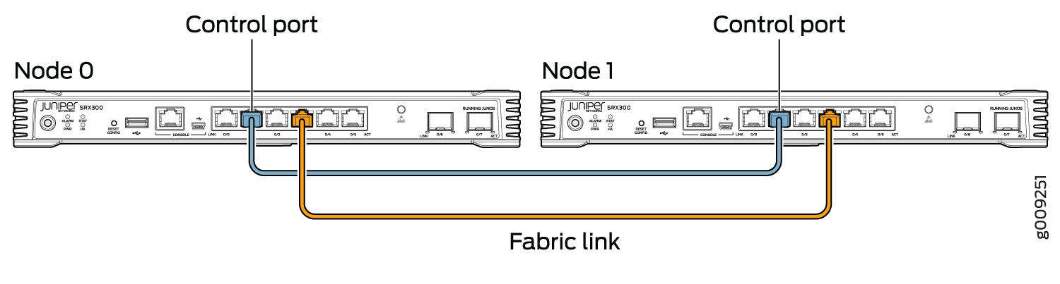
For SRX300 devices, connect the ge-0/0/1 on node 0 to the ge-1/0/1 on node 1.
-
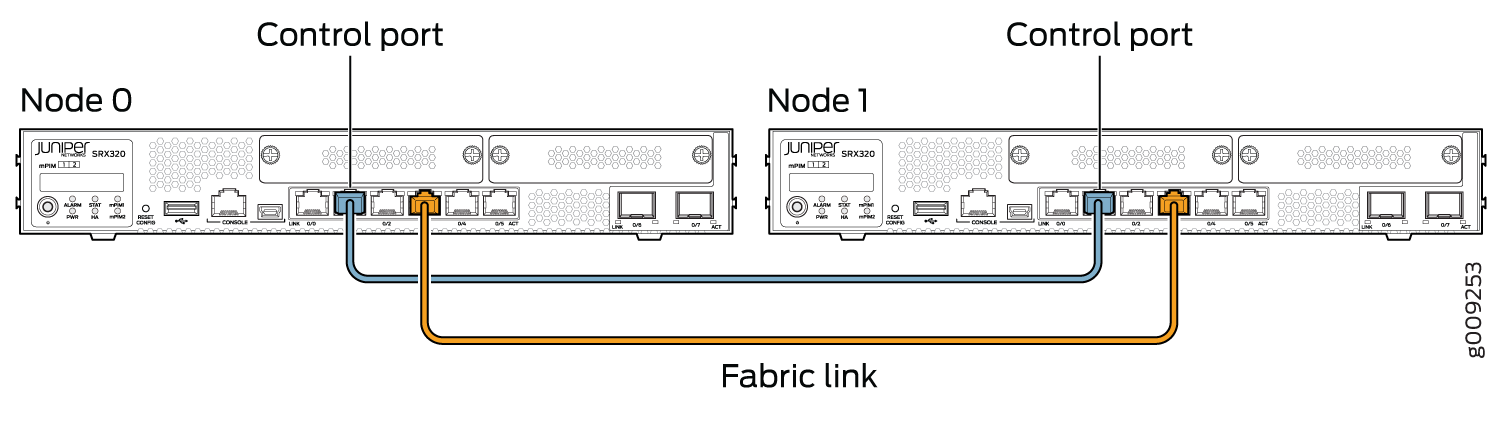
For SRX320 devices, connect the ge-0/0/1 on node 0 to the ge-3/0/1 on node 1.
-
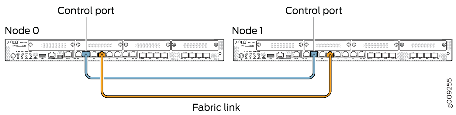
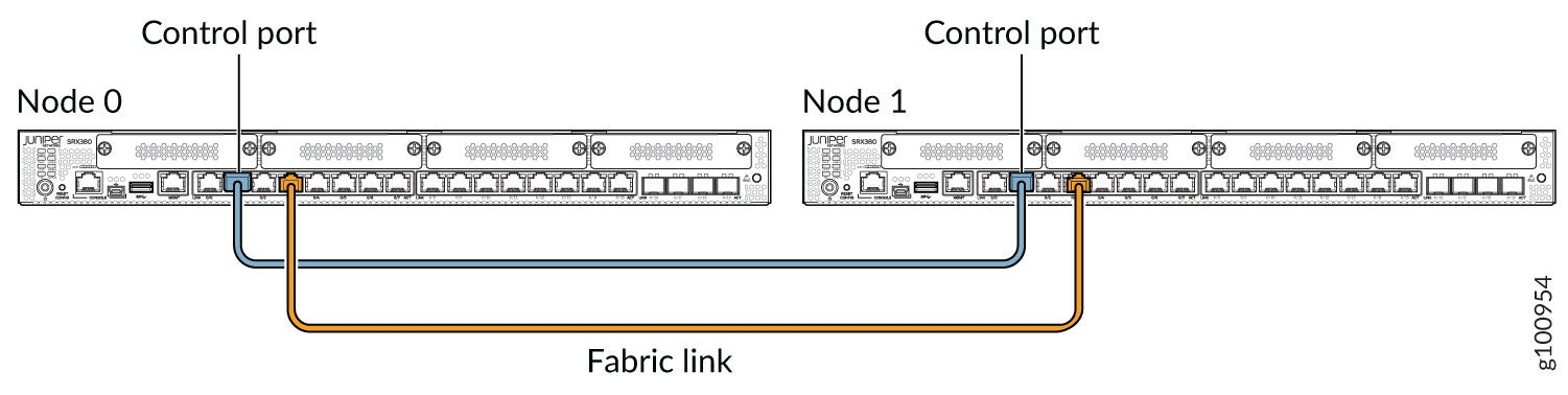
For SRX340, SRX345, and SRX380 devices, connect the ge-0/0/1 on node 0 to the ge-5/0/1 on node 1.
-
For SRX1500 devices, connect the HA control port on node 0 to the HA control port on node 1.
-
For SRX1600, SRX2300, SRX4120, and SRX4300 devices dual control link configuration, connect the HA control port 0 on node 0 to the HA control port 0 on node 1 and connect the HA control port 1 on node 0 to the control port 1 on node 1.
To establish a fabric link:
-
For SRX300 and SRX320 devices, connect any interface except ge-0/0/0 and ge-0/0/1.
-
For SRX340, SRX345, and SRX380 devices, connect any interface except fxp0 and ge-0/0/1.
Figure 2, Figure 3, Figure 4, and Figure 6 show pairs of Firewalls with the fabric links and control links connected.

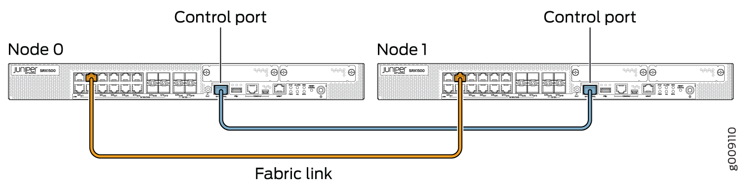
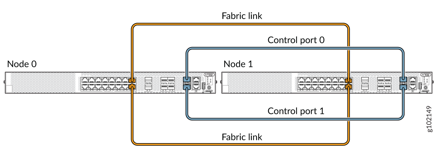
For SRX1500, SRX1600, SRX2300, SRX4120, and SRX4300 devices, the connection that serves as the control link must be between the built-in control ports on each device.
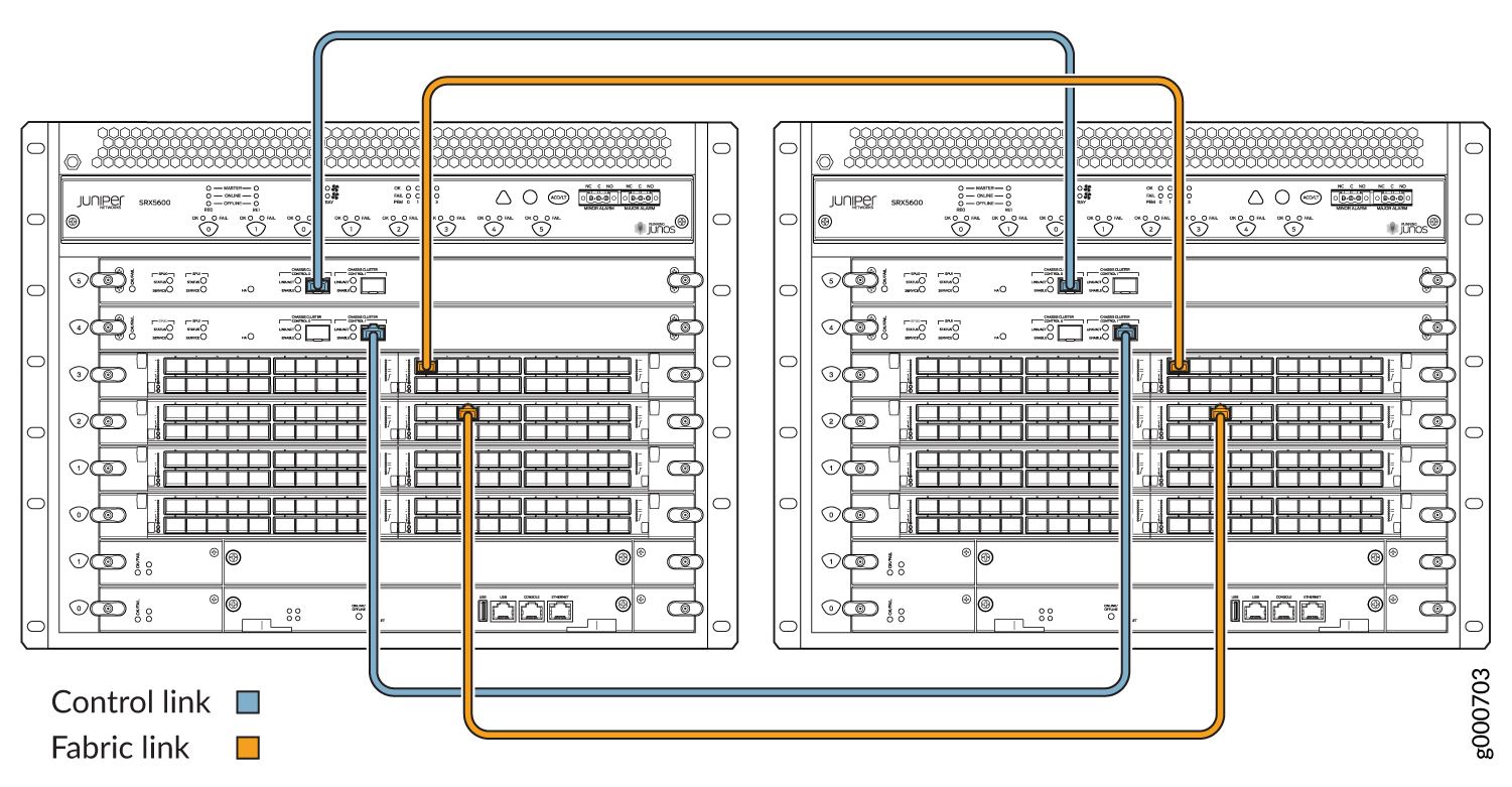
You can connect two control links (SRX4600, SRX5600, and SRX5800) and two fabric links between the two devices in the cluster to reduce the chance of control link and fabric link failure. See Understanding Chassis Cluster Dual Control Links and Understanding Chassis Cluster Dual Fabric Links.
Figure 12, Figure 9 and Figure 10 show pairs of Firewalls with the fabric links and control links connected.
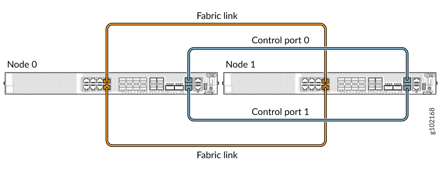
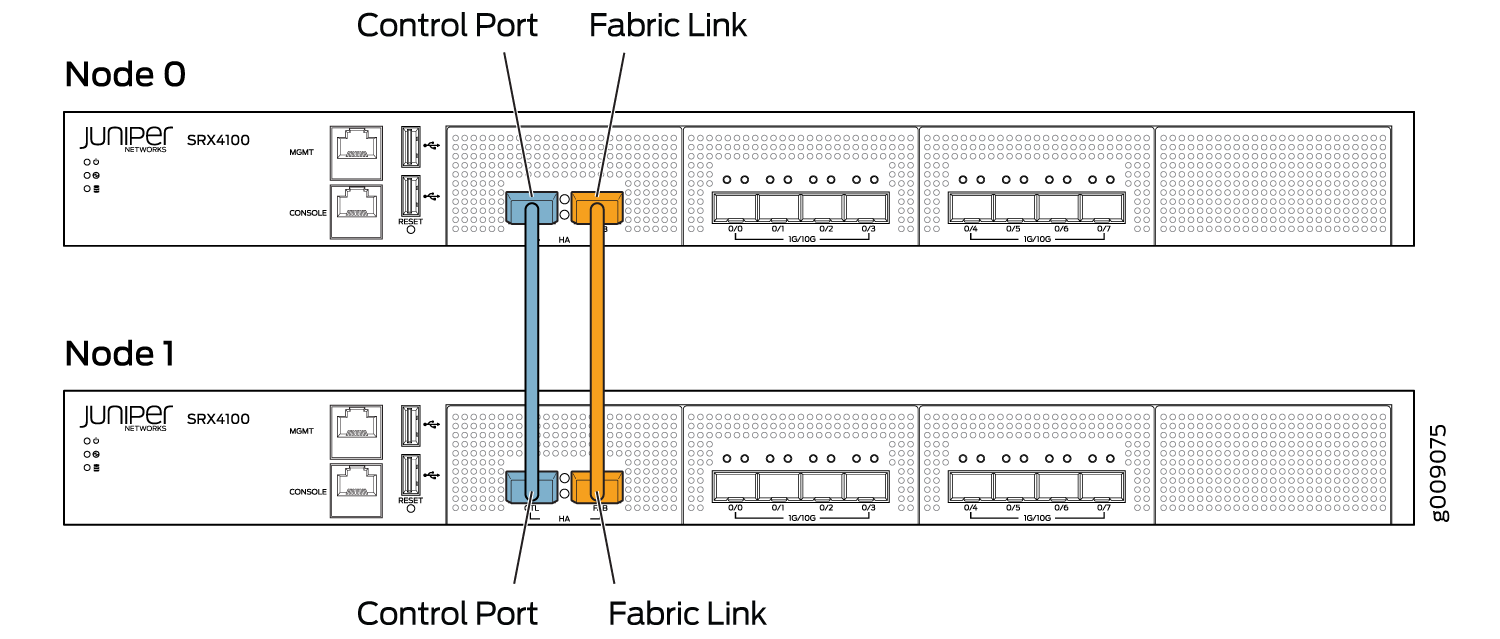
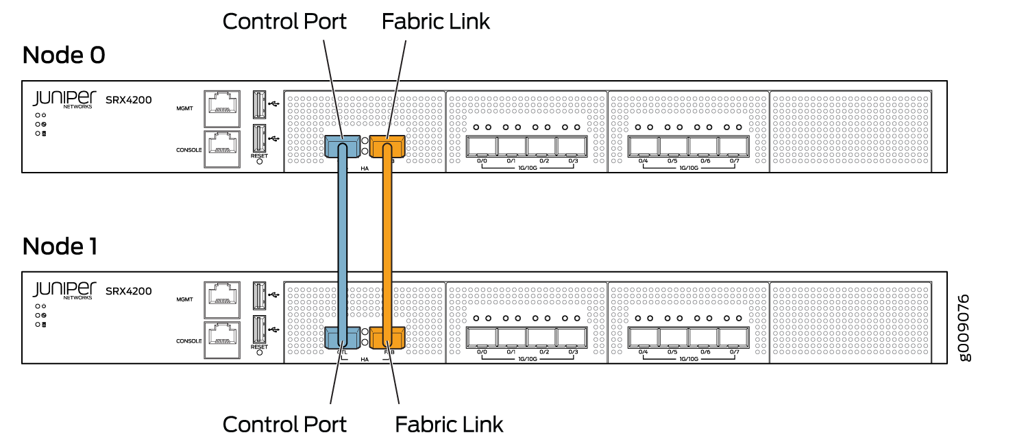
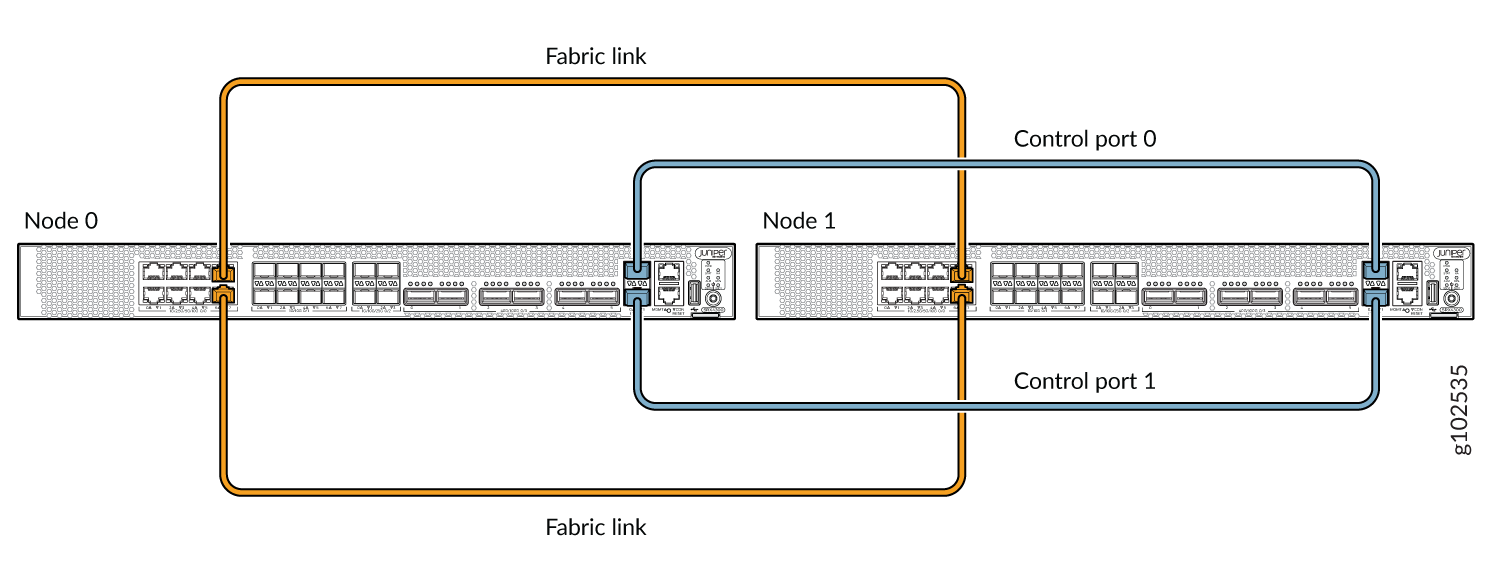
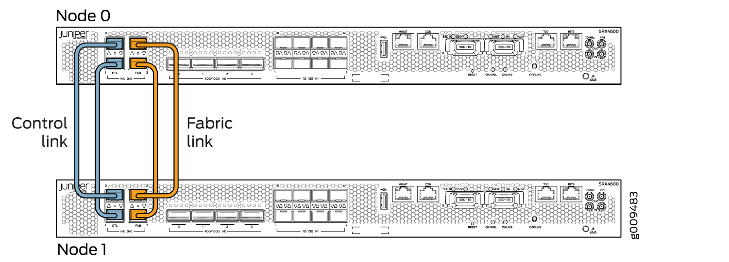
Figure 13, Figure 14, and Figure 15 show pairs of Firewalls with the fabric links and control links connected.
Service Processing Cards (SPC) have two dedicated ports ( HA0 and HA1) for connecting the control links in the chassis cluster.
Fabric ports are revenue ports available from any IOC card. Fabric links are connected to the same slot and port on both SRX5000 line of Firewalls.
SRX5000 line of Firewalls do not have built-in ports, so the control link for these gateways must be the control ports on their SPCs with a slot numbering offset of 3 for SRX5400, offset of 6 for SRX5600 devices and 12 for SRX5800 devices.
Figure 13 shows pair of SRX5800 devices having single SPC card each connected with a control link. The fabric link is connected using the IOC card. Dual control links are set up using one SPC card on each node. It is recommended to separate the primary and secondary control ports on two different SPC cards on each node for redundancy.
Figure 14 shows dual control links connected using two SPC3 cards and dual fabric links using IOC cards.
When you connect a single control link on SRX5000 line of Firewalls, the control link ports are a one-to-one mapping with the Routing Engine slot. If your Routing Engine is in slot 0, you must use control port 0 to link the Routing Engines.
When a SPC is the central point as well as hosting the control port, this creates a single point of failure. If the SPC goes down on the primary node, the node is automatically rebooted to avoid split brain.
Dual control links are not supported on an SRX5400 device due to the limited number of slots.