Service Chaining Design and Implementation
For an overview of service chaining, see the Service Chaining section in Data Center Fabric Blueprint Architecture Components.
The following sections show how to implement service chaining and service chaining of multicast in a EVPN VXLAN network.
Service Chaining
Service Chaining Design
Figure 1 shows a logical view of the service chaining configuration. It shows the configuration of one spine with a left and right side VRF configuration. The SRX Series router is the PNF, and is performing the Service chaining.
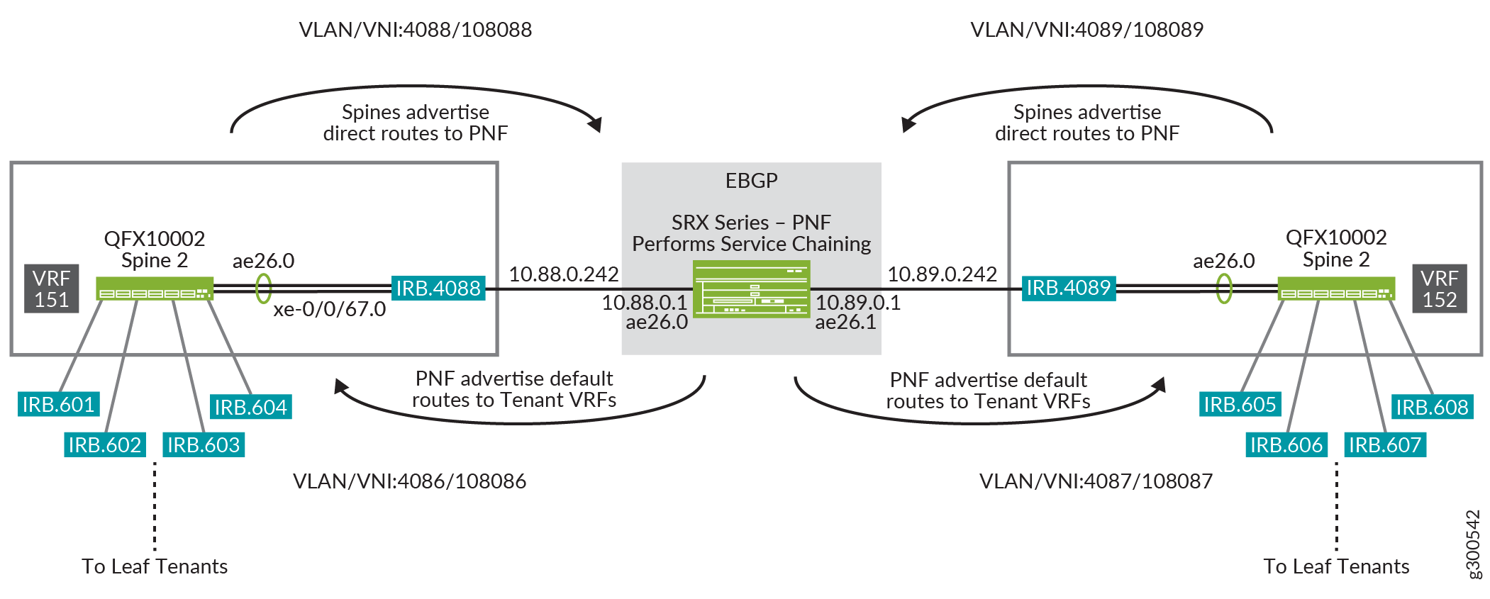
The flow of traffic for the spine:
Traffic from the leaf tenants enters tenant VRF-151, and is destined to a network attached to tenant VRF-152.
Because there is no route from VRF-151 to VRF-152, a default route lookup is performed using routes received from the PNF.
After it receives the default route from the PNF, VRF-151 routes traffic toward the PNF via IRB.4088.
Traffic reaches the PNF, and the PNF performs the service chaining. Traffic is forwarded out ae26.1 using routes received from EBGP.
Traffic now reaches tenant VRF-152, and follows regular route lookup and forwarding action towards the leaf tenants.
Configuring Service Chaining
This section shows how to configure the spine for service chaining as shown in Figure 1. This configuration is based on the Centrally-Routed Bridging Overlay Design and Implementation configuration.
Verifying Service Chaining
To verify that service chaining is working:
Service Chaining with Multicast
- Service Chaining with Multicast Design
- Configuring Service Chaining With Multicast
- Verifying Service Chaining with Multicast
Service Chaining with Multicast Design
Figure 2 shows the logical view of the service chaining configuration. The VRF routing instances and IRB interfaces are all configured on the same spine.
In this design, we are performing service chaining with an SRX Series router as the PNF and with a PIM gateway.
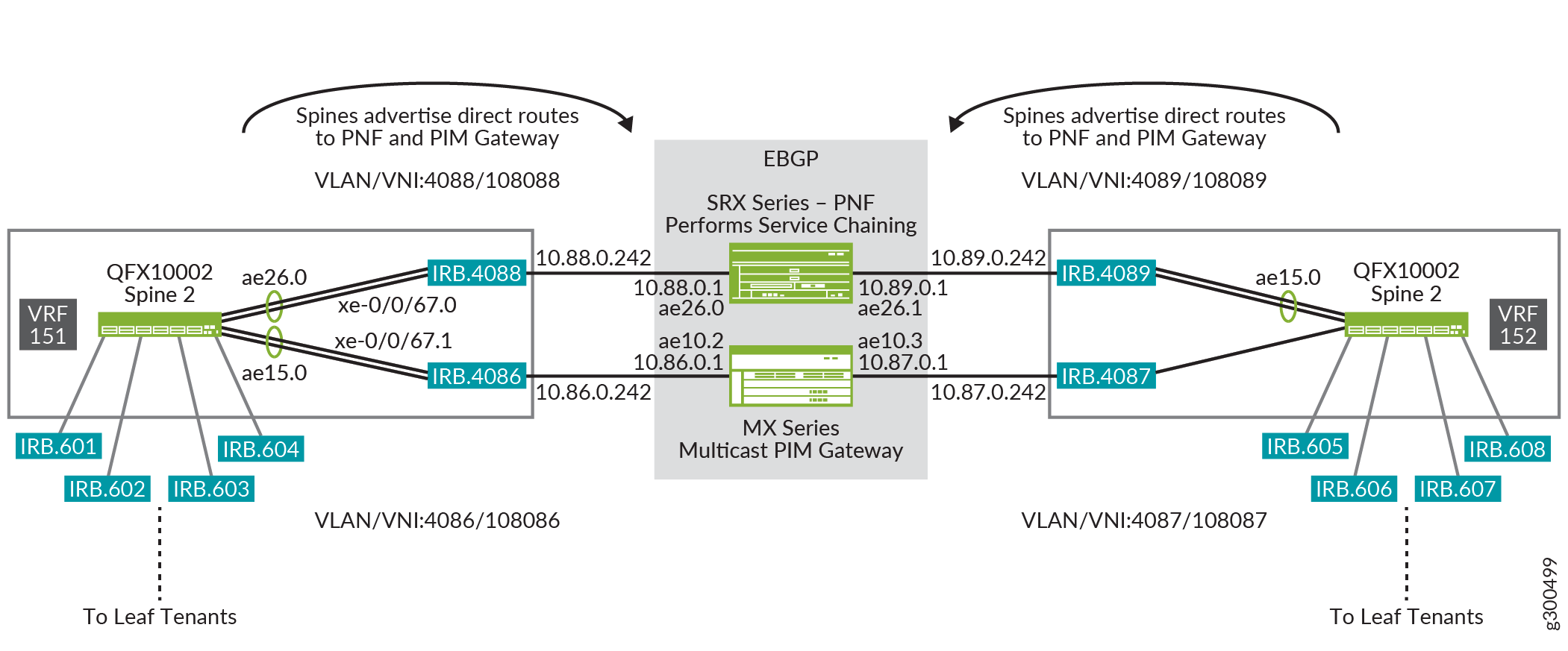
The flow of traffic for Spine 2 when multicast receivers start sending IGMP reports:
The leaf devices snoop the IGMP report and advertise EVPN Type 6 routes to the spines to notify the spines of the interested Multicast receiver.
The spine receives the EVPN Type 6 routes based on the VNI mapping, and creates a PIM join (*.G) entry in VRF-152.
The spine configuration includes the address of the RP on the PIM gateway. However, on the VRF-152 routing instance, there is only a default route toward the RP via the PNF.
The PIM designated router (DR) on the receiver side IRBs (irb.605, irb.606 irb.607, irb.608) sends a PIM join (*.G ) towards the PNF device on irb.4089.
The PNF device, creates a PIM (*.G) entry with ae26.1 as the outgoing interface.
The PNF is configured with the RP.
On the PNF, the RP is also configured on the PNF and the lookup to the PIM RP points toward interface ae26.0 -> interface towards VRF-151 on spines
The PIM join arrives on VRF-151 on irb.4088 and creates a PIM ( *,G ) state with irb.4088 as the outgoing interface and lookup towards the RP points to irb.4086.
The Spine sends the PIM join entry on irb.4086 towards the PIM gateway.
The PIM gateway receives the PIM (*,G ) join on ae10.2.
The flow of traffic for Spine 2 when the multicast source on VRF-151 starts sending packets:
VRF-151 creates a PIM (*,G ) entry with irb.4088 as the outgoing interface and also the RP reachable via irb.4086.
Spine 2 sends two packets—one toward the PNF on irb.4088 and one toward the PIM gateway on irb.4086.
When the PNF receives the packet:
The PNF forwards it based on the PIM ( *.G ) entry it created with outgoing interface ae26.1
Multicast traffic arrives on irb.4089 in VRF-512 and is forwarded to the receivers on the leafs.
When the PIM gateway receives the packet, it forwards the packet based on its (*,G) PIM entry with the outgoing interface as ae10.2.
When traffic arrives at irb.4086 from the PIM gateway on Spine 2, Spine 2 prunes the RPT/shared tree.
Configuring Service Chaining With Multicast
This section shows how to configure the spine for service chaining as shown in Figure 2.
Verifying Service Chaining with Multicast
This section shows how to configure service chaining with Multicast. Note the following:
The multicast source is on VRF-151 - VLAN 601
The multicast receivers are on VRF-152 - VLAN 606
Service Chaining— Release History
Table 1 provides a history of all of the features in this section and their support within this reference design.
Release |
Description |
|---|---|
19.1R2 |
QFX10002-60C and QFX5120-32C switches running Junos OS Release 19.1R2 and later releases in the same release train support all features documented in this section. |
18.4R2 |
QFX5120-48Y switches running Junos OS Release 18.4R2 and later releases in the same release train support all features documented in this section. |
18.1R3-S3 |
All devices in the reference design that support Junos OS Release 18.1R3-S3 and later releases in the same release train also support all features documented in this section. |