Data Center Interconnect Design and Implementation Using Type 5 Routes
Data Center Interconnect Using EVPN Type 5 Routes
EVPN Type 5 routes, also known as IP prefix routes, are used in a DCI context to pass traffic between data centers that are using different IP address subnetting schemes.
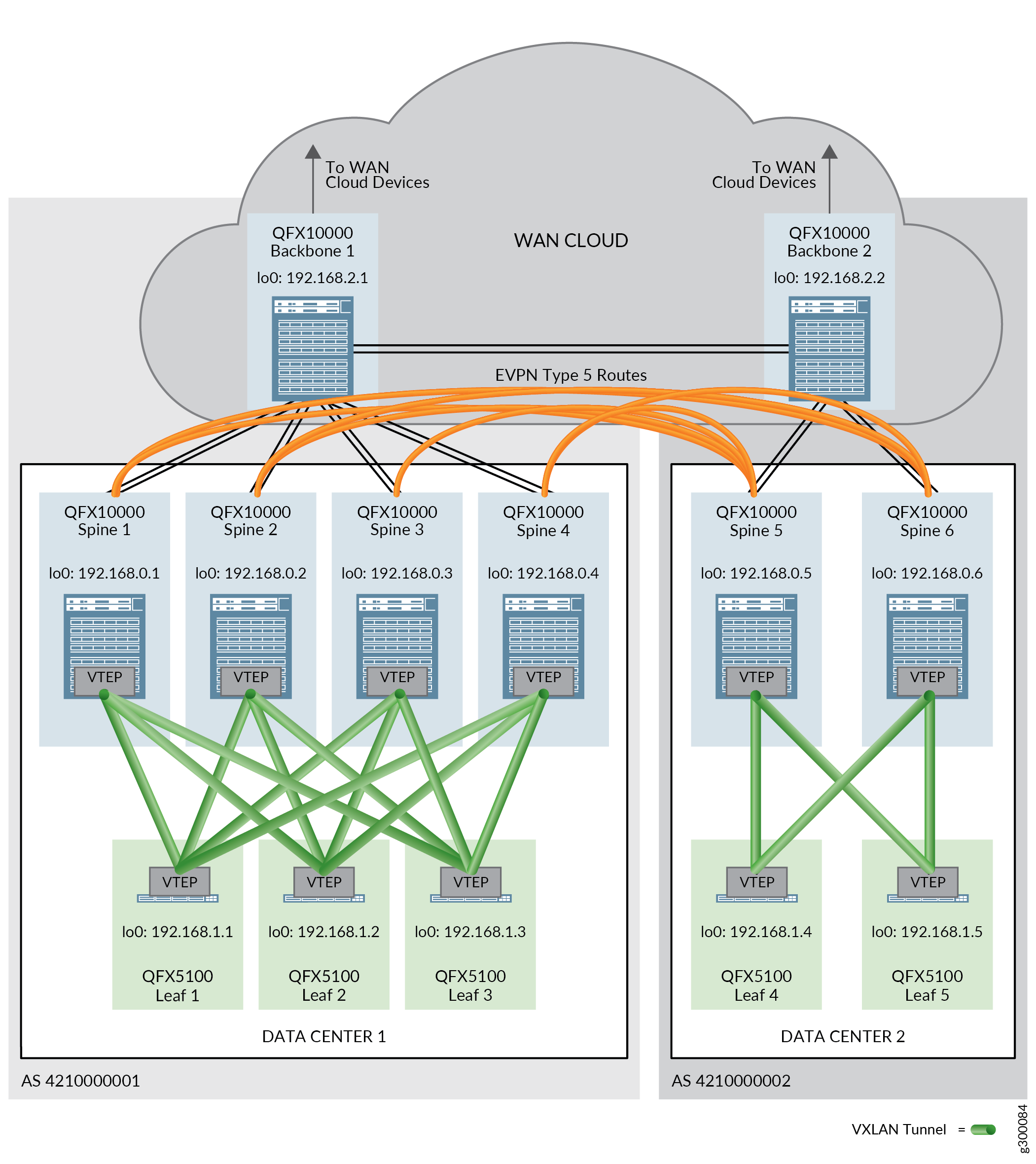
In this reference architecture, EVPN Type 5 routes are exchanged between spine devices in different data centers to allow for the passing of traffic between data centers.
Physical connectivity between the data centers is required before EVPN Type 5 messages can be sent across data centers. This physical connectivity is provided by backbone devices in a WAN cloud. A backbone device is connected to each spine device in a single data center and participates in the overlay IBGP and underlay EBGP sessions. EBGP also runs in a separate BGP group to connect the backbone devices to each other; EVPN signaling is enabled in this BGP group.
Figure 1 shows two data centers using EVPN Type 5 routes for DCI.
For additional information on EVPN Type 5 routes, see EVPN Type-5 Route with VXLAN encapsulation for EVPN-VXLAN.
All procedures in this section assume that EVPN Type 2 routes are successfully being passed in the data centers. See Centrally-Routed Bridging Overlay Design and Implementation for setup instructions.
This section covers the processes for configuring a DCI using EVPN Type 5 routes, and includes the following procedures:
- Configuring Backbone Device Interfaces
- Enabling EBGP as the Underlay Network Routing Protocol Between the Spine Devices and the Backbone Devices
- Enabling IBGP for the Overlay Network on the Backbone Device
- Enabling EBGP as the Routing Protocol Between the Backbone Devices
- Configuring DCI Using EVPN Type 5 Routes
- Verifying That DCI Using EVPN Type 5 Routes is Operating
- DCI Using Type 5 Routes — Release History
Configuring Backbone Device Interfaces
The backbone devices in this architecture are part of the WAN cloud and must provide connectivity both to the spine devices in each data center as well as to the other backbone device. This connectivity must be established before EVPN Type 5 routes can be exchanged between spine devices in different data centers.
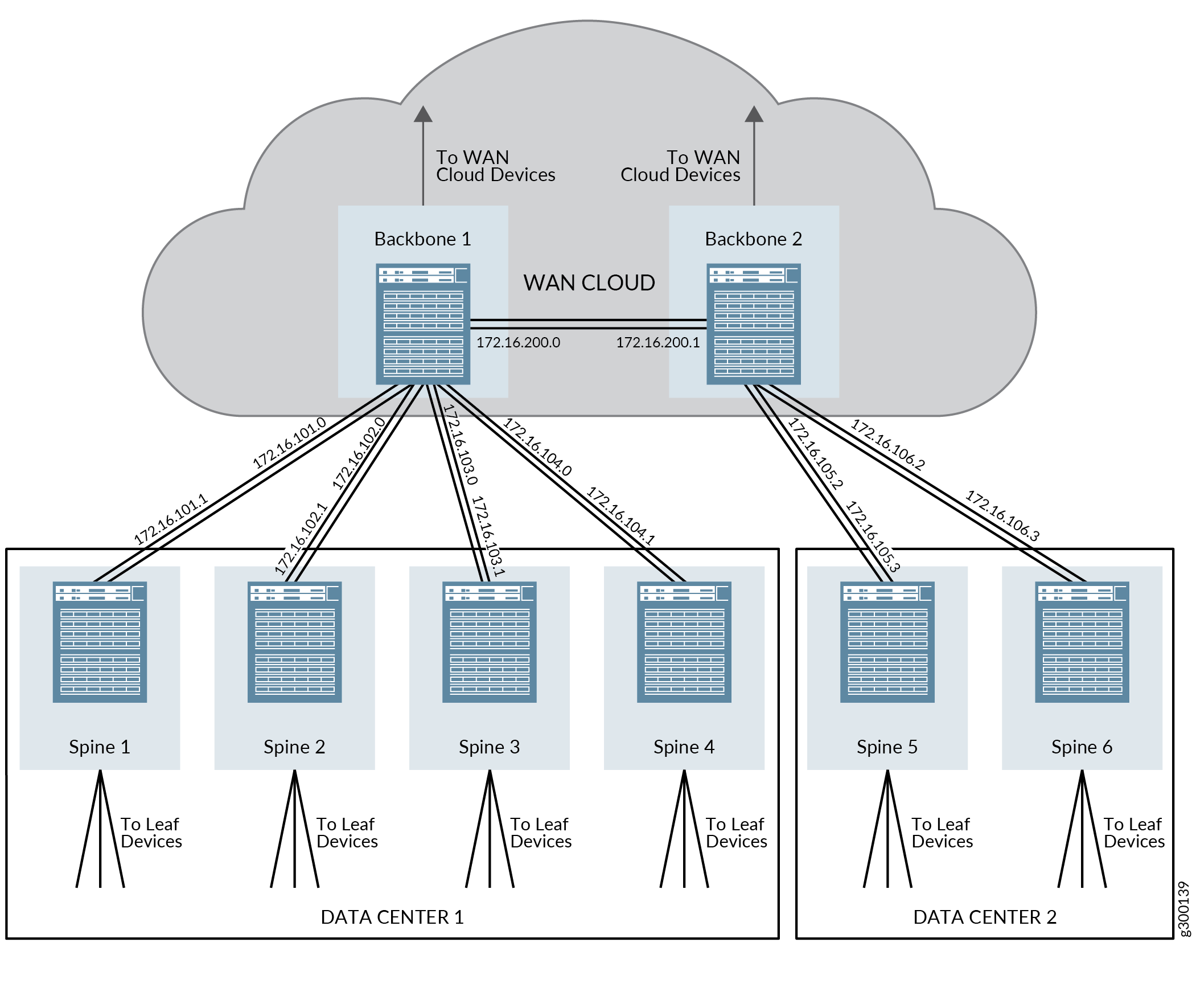
Figure 2 provides an overview of the IP addresses that are configured in these steps.
To configure the spine device and backbone device interfaces:
(Aggregated Ethernet interfaces) Configure the aggregated Ethernet interfaces on the spine device switches in Data Centers 1 and 2 and on the backbone devices.
This step shows the assignment of the IP address to the aggregated Ethernet interfaces only. For complete step-by-step instructions on creating aggregated Ethernet interfaces, see Configuring Link Aggregation.
Spine Device 1 in Data Center 1:
set interfaces ae3 unit 0 family inet address 172.16.101.1/31
Spine Device 2 in Data Center 1:
set interfaces ae3 unit 0 family inet address 172.16.102.1/31
Spine Device 3 in Data Center 1:
set interfaces ae3 unit 0 family inet address 172.16.103.1/31
Spine Device 4 in Data Center 1:
set interfaces ae3 unit 0 family inet address 172.16.104.1/31
Spine Device 5 in Data Center 2:
set interfaces ae4 unit 0 family inet address 172.16.105.3/31
Spine Device 6 in Data Center 2:
set interfaces ae4 unit 0 family inet address 172.16.106.3/31
Backbone Device 1:
set interfaces ae1 unit 0 family inet address 172.16.101.0/31
set interfaces ae2 unit 0 family inet address 172.16.102.0/31
set interfaces ae3 unit 0 family inet address 172.16.103.0/31
set interfaces ae4 unit 0 family inet address 172.16.104.0/31
set interfaces ae200 unit 0 family inet address 172.16.200.0/31
Backbone Device 2:
set interfaces ae5 unit 0 family inet address 172.16.105.2/31
set interfaces ae6 unit 0 family inet address 172.16.106.2/31
set interfaces ae200 unit 0 family inet address 172.16.200.1/31
(Standalone interfaces that are not included in aggregated Ethernet interfaces) See Configuring the Interface Address.
Enabling EBGP as the Underlay Network Routing Protocol Between the Spine Devices and the Backbone Devices
EBGP is used as the routing protocol of the underlay network in this reference design. The backbone devices must participate in EBGP with the spine devices to support underlay connectivity.
The process for enabling EBGP on the spine and leaf devices is covered in the IP Fabric Underlay Network Design and Implementation section of this guide. This procedure assumes EBGP has already been enabled on the spine and leaf devices, although some EBGP configuration on the spine devices needs to be updated to support backbone devices and is therefore included in these steps.
EBGP works in this reference design by assigning each leaf, spine, and backbone device into it’s own unique 32-bit autonomous system (AS) number.
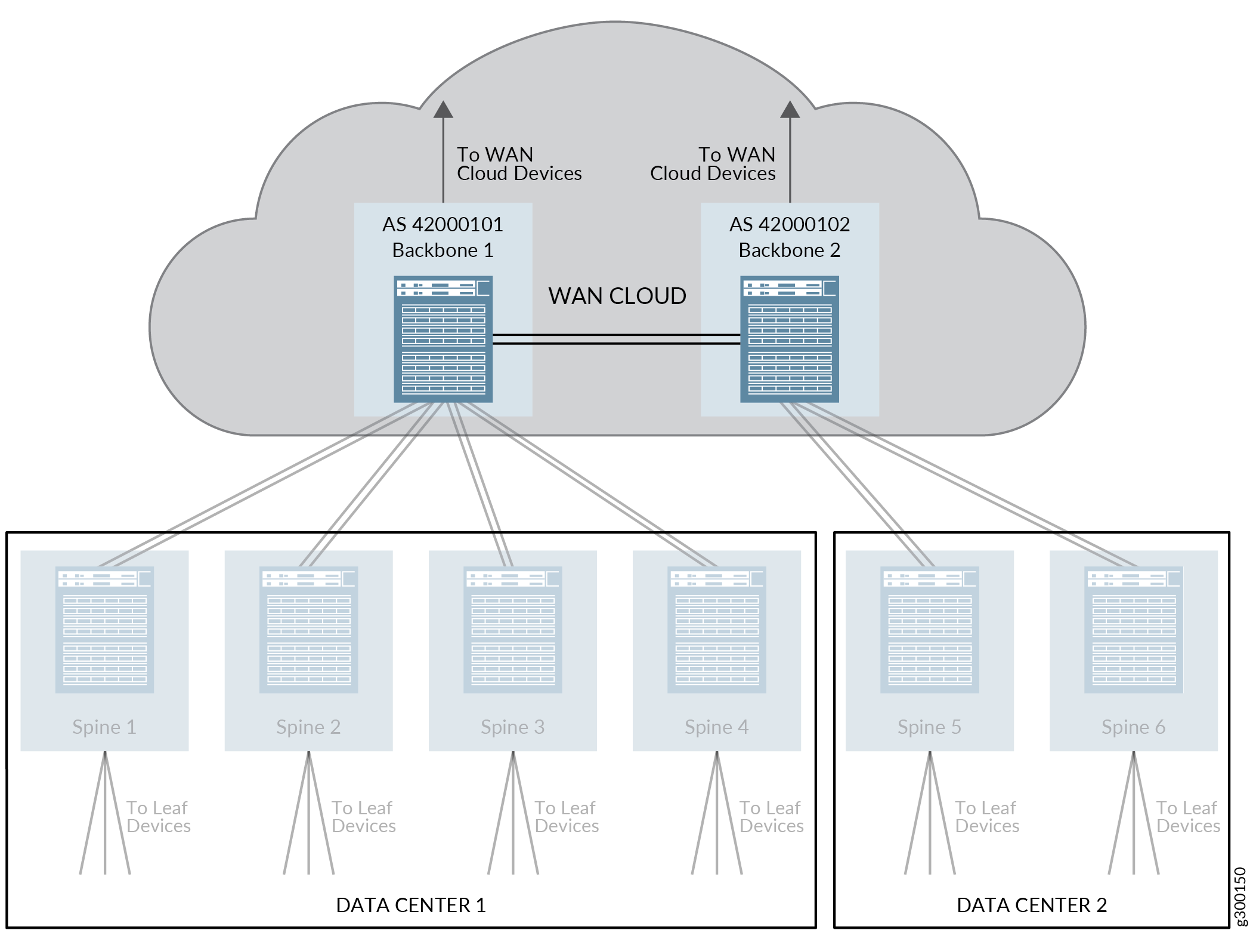
Figure 3 shows an overview of the EBGP topology for the spine and backbone devices when backbone devices are included in the reference design.
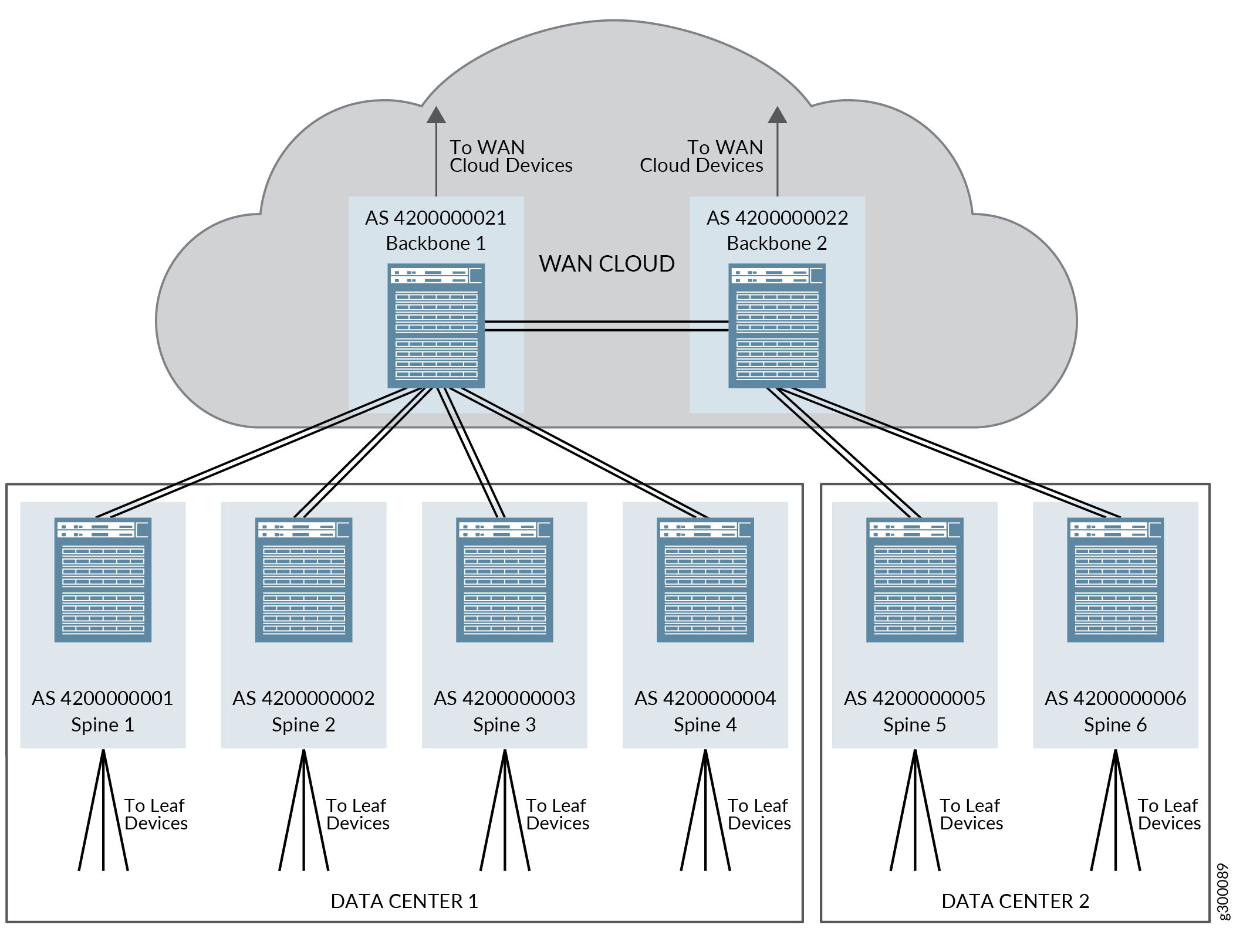
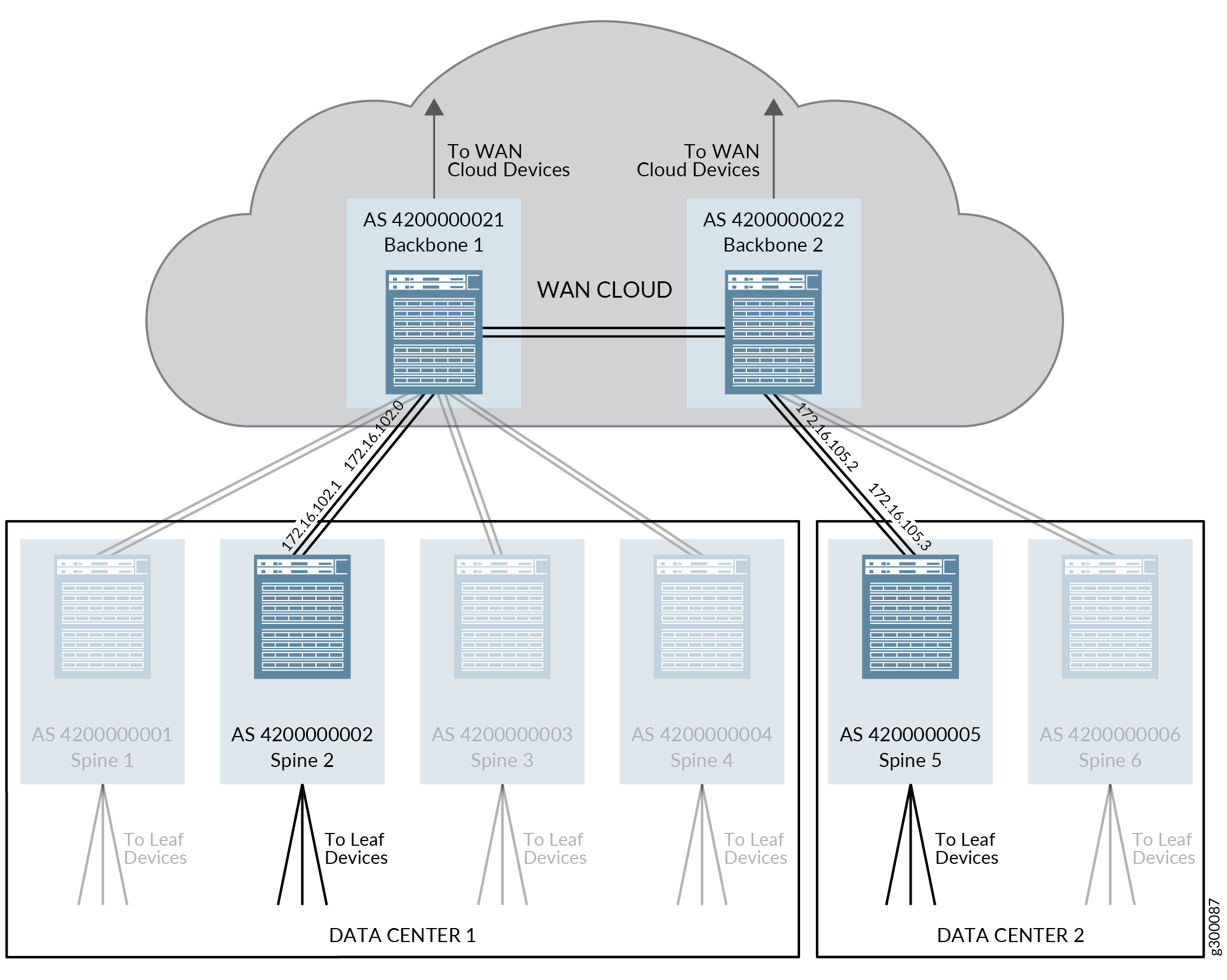
Figure 4 illustrates the EBGP protocol parameters that are configured in this procedure. Repeat this process for the other devices in the topology to enable EBGP on the remaining devices.
To enable EBGP to support the underlay network in this reference design:
Enabling IBGP for the Overlay Network on the Backbone Device
The backbone devices must run IBGP to have overlay network connectivity and be able to support DCI using EVPN Type 5 routes.
Figure 5 shows the IBGP configuration of the validated reference design when backbone devices are included in the topology. In the validated reference design, all spine and leaf devices in the same data center are assigned into the same autonomous system. The backbone devices are assigned into the same autonomous system as the spine and leaf devices of the data center that is using the backbone device as the entry point into the WAN cloud.
Figure 6 illustrates the route reflector configuration in the validated reference design. One route reflector cluster—cluster ID 192.168.2.10—includes backbone device 1 as the route reflector and all spine devices in data center 1 as route reflector clients. Another route reflector cluster—cluster ID 192.168.2.11—includes backbone device 2 as the route reflector and all spine devices in data center 2 as route reflector clients.
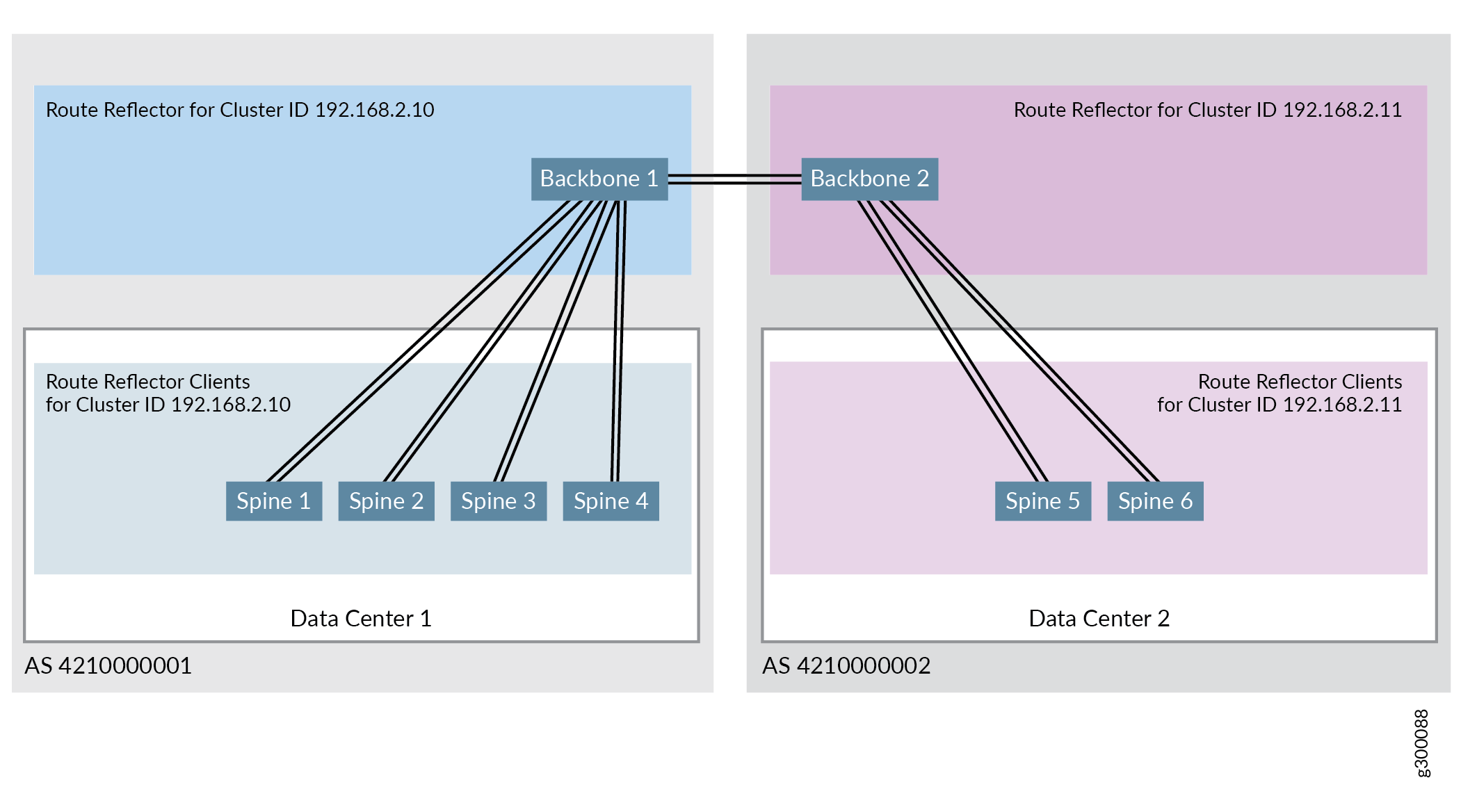
The validated reference design supports multiple hierarchical route reflectors, where one cluster includes backbone devices acting as route reflectors for the spine device clients and another cluster includes spine devices acting as route reflectors for leaf device clients. To see the configuration steps for configuring the other route reflector, see Configure IBGP for the Overlay.
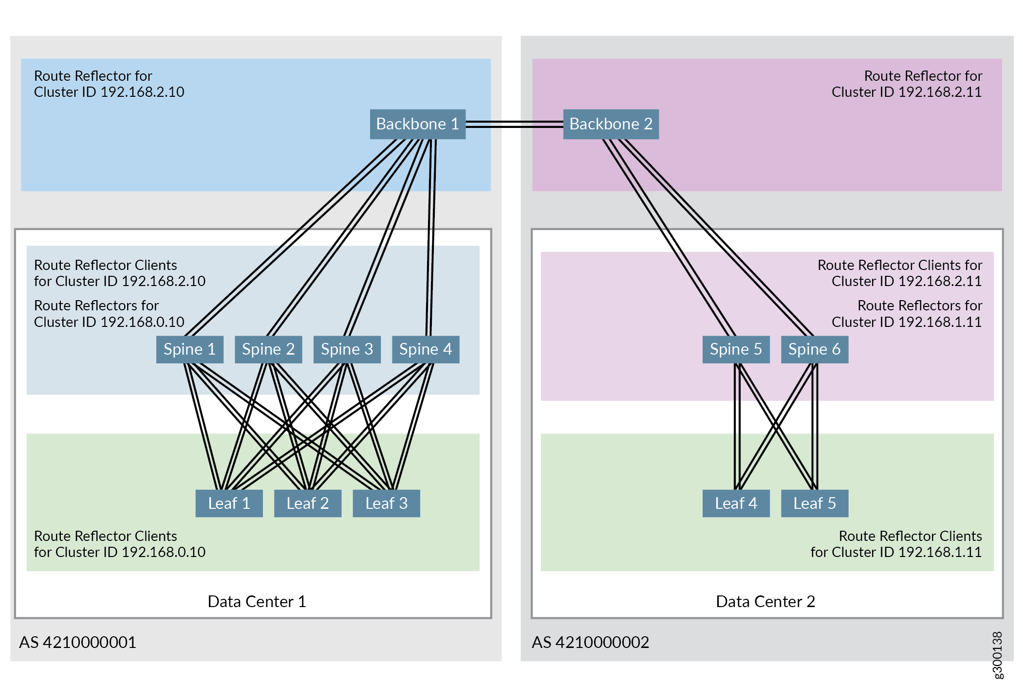
Figure 7 shows the full hierarchical route reflector topology when two data centers are connected:
For more information on BGP route reflectors, see Understanding BGP Route Reflectors.
This procedure assumes IBGP has been enabled for the spine and leaf devices as detailed in Configure IBGP for the Overlay. The spine device configurations are included in this procedure to illustrate their relationships to the backbone devices.
To setup IBGP connectivity for the backbone devices:
Enabling EBGP as the Routing Protocol Between the Backbone Devices
EBGP is also used as the routing protocol between the backbone devices in this reference design. The backbone devices are connected using IP and the backbone devices must be configured as EBGP peers.
A second EBGP group—BACKBONE-BGP—is created in these steps to enable EBGP between the backbone devices. Each backbone device is assigned into a unique 32-bit AS number within the new EBGP group in these steps. The backbone devices, therefore, are part of two EBGP groups—UNDERLAY-BGP and BACKBONE-BGP—and have a unique AS number within each group. EVPN signaling, which has to run to support EVPN between the backbone devices, is also configured within the EBGP group during this procedure.
Figure 8 illustrates the attributes needed to enable EBGP between the backbone devices.
To enable EBGP as the routing protocol between the backbone devices:
Configuring DCI Using EVPN Type 5 Routes
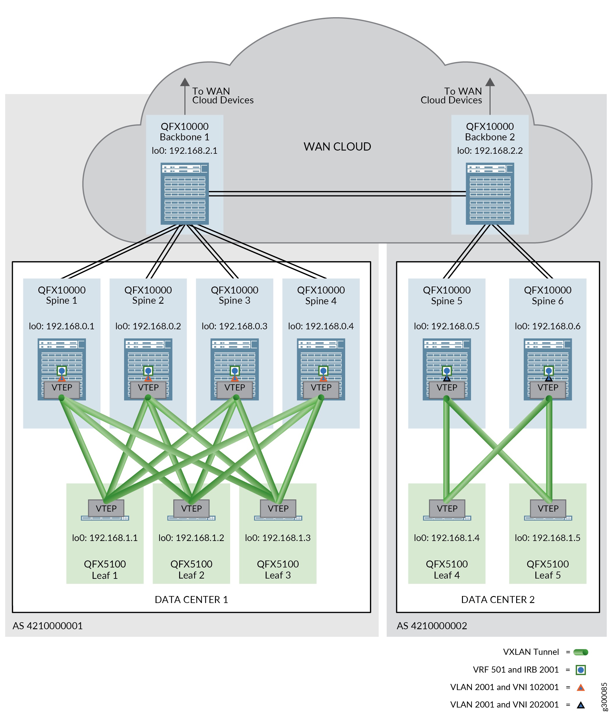
EVPN Type 5 messages are exchanged between IRB interfaces on spine devices in different data centers when EVPN Type 5 routes are used for DCI. These IRB interfaces are configured in a routing instance.
Each data center has a unique virtual network identifier (VNI 102001 and 202001) in this configuration, but both VNIs are mapped to the same VLAN (VLAN 2001) in the same routing instance (VRF 501).
See Figure 9 for an illustration of the routing instance.
To enable DCI using EVPN Type 5 routes:
This procedure assumes that the routing instances, IRBs, & VLANs created earlier in this guide are operational. See Centrally-Routed Bridging Overlay Design and Implementation.
When implementing border leaf functionality on an MX router, keep in mind that the router supports virtual switch instances only. MX routers do not support default instances.
Verifying That DCI Using EVPN Type 5 Routes is Operating
Enter the following commands to verify that traffic can be sent between data centers using EVPN Type 5 routes:
DCI Using Type 5 Routes — Release History
Table 1 provides a history of all of the features in this section and their support within this reference design.
Release |
Description |
|---|---|
19.1R2 |
QFX10002-60C and QFX5120-32C switches running Junos OS Release 19.1R2 and later releases in the same release train support all features documented in this section. |
18.4R2-S2 |
QFX5110 and QFX5120-48Y switches, and MX routers running Junos OS Release 18.4R2-S2 and later releases in the same release train support all features documented in this section. |