ON THIS PAGE
Part 1: Initial Configuration for Internet Connectivity
Example Overview
This configuration example shows how to deploy a small to mid-size branch office with an SRX Services gateway, EX Series switches, and Mist APs. The example uses two WAN links in Active/Active mode with an LTE backup link. In addition, the Juniper Mist Cloud is used to configure the EX switch and Mist AP as part of wired and wireless assurance, respectively.
The example also shows how to use performance monitoring and policy based routing to provide Application Quality of Experience (AppQoE). AppQoE intelligently prioritizes business critical traffic when one or more links fail.
Requirements
You’ll need the following hardware and software to configure this example:
One SRX300 Series device (SRX320, SRX340, SRX345, SRX380) or an SRX5000 Series device (SRX550M): Software version: Junos OS Version 19.4R1 or higher.
This example requires installation of an application identification license, and the download and install of the application identification package. See Licenses for SRX Series for more information. Use the
show system
                  license
and theshow services application-identification statuscommands.Note:Updates to the Junos OS application signature package is authorized by a separately licensed subscription service. You must install the application identification application signature update license key on your device to download and then install the signature database updates provided by Juniper Networks. When your license key expires, you can continue to use the locally stored application signature package contents but you cannot update the package.
One EX Series Ethernet switch (EX2300, EX3400, or EX4300): Software version: Junos OS 19.4R1 or higher.
One or more MIST access points (AP12, AP41, AP43, AP61, or AP32).
One LTE Mini-PIM for the SRX Services Gateway.
One SIM card with a subscription for data services.
A Juniper Mist Cloud login. Create your account at: Juniper Mist Cloud .
Deployment Details
In this example, we configure an SRX550 to provide DHCP and SNAT. The SRX provides secure outgoing Internet access for the EX switch, Mist AP, and the on site client devices. The primary link connects to a private WAN network (for example, a Virtual Private LAN Service (VPLS)), the secondary link uses broadband Internet over Ethernet access. The backup link uses an LTE cellular network.
The primary and secondary links operate in Active/Active mode. The LTE modem is not used unless both the primary and secondary links go down.
The EX4300-24P switch used in this example connects to the SRX device and provides the wired Layer 2 functionality (bridging) for the branch. A virtual chassis (VC) of multiple EX2300, EX3400, and EX4300 switches supports higher port density for larger branch locations. For wireless access, we connect a Juniper Mist AP61 access point to the EX switch.
The Juniper Mist Cloud quickly provisions the EX series switch and the Mist AP for the desired branch connectivity once the branch has the required Internet access.
A range of SRX Services Gateways are supported in this example. We begin with a modified factory default configuration for an SRX550. The factory default configuration can vary between SRX models. The reader must ensure that their SRX configuration matches the specifics of their topology.
The example has three main sections:
First, you perform initial configuration on the SRX and EX. This configuration provides Internet access to the branch site (with S-NAT) for the EX, the Mist AP, and the branch office's VLANs.
Next, you use the Juniper Mist Cloud to provision the EX switch and Mist AP to provision the wireless connectivity for branch office's VLANs.
In the last part you configure the SRX Services gateway to provide Advanced Policy Based Routing (APBR) to support Application Quality of Experience (AppQoE). This configuration maps business traffic to the desired link and implements SLA probes to determine when traffic should fall over to a backup link. This policy also activates the LTE modem when both the primary and secondary links fail to meet the related SLAs.
Figure 1 shows the branch office topology.
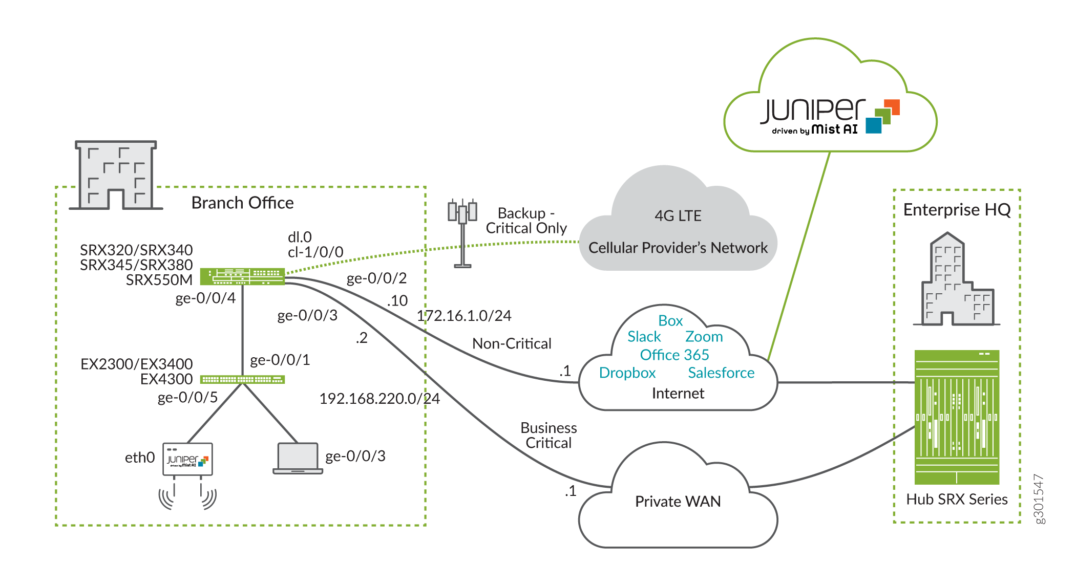
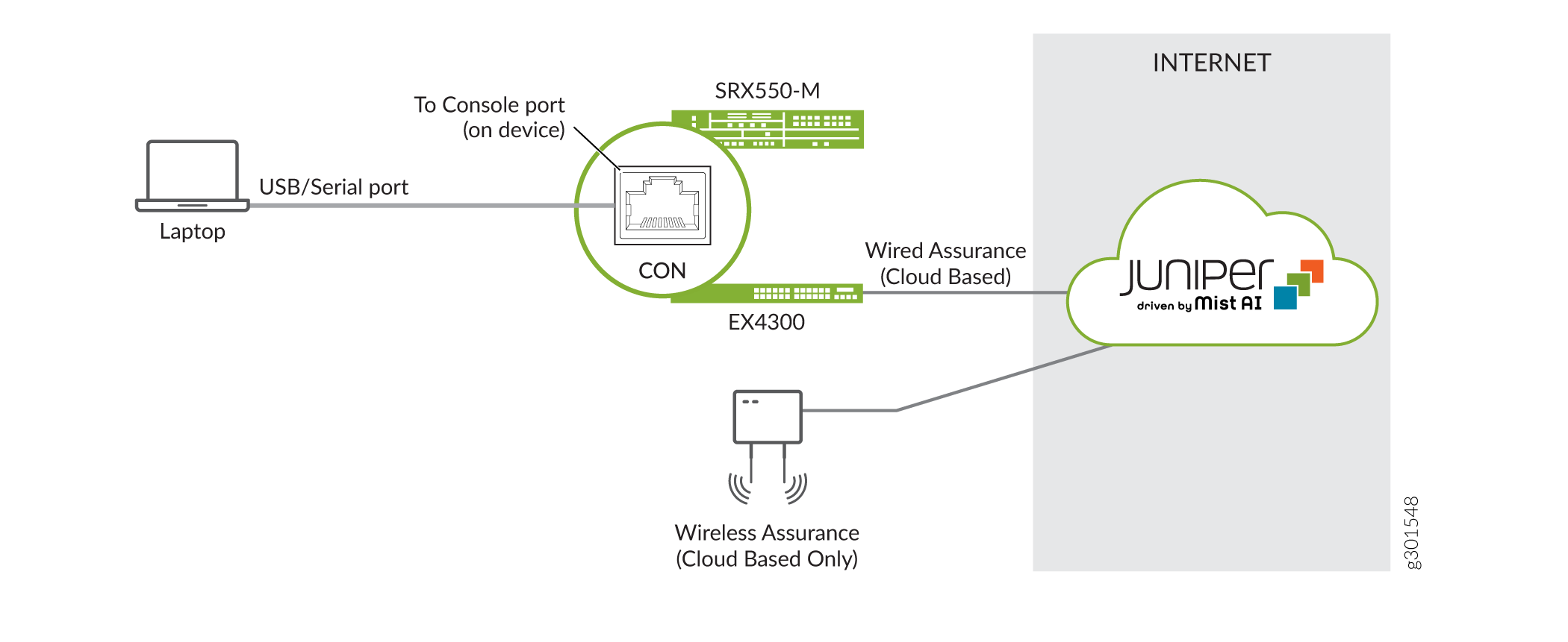
Figure 2 shows the management network for the branch office example. In this example we rely on console access. The SRX and EX devices support an Ethernet based management network. The Mist AP can only be managed through the cloud.
Our topology has the following hardware layout on the SRX Series device:
A minimal baseline configuration is loaded on the SRX. A later section provides the starting baseline.
Slot 1 on the SRX Series device contains an LTE Mini-PIM.
Slot 1 of the LTE Mini-PIM has a SIM card installed.
The ge-0/0/3 interface connects to the primary WAN link.
The ge-0/0/2 interface attaches to the broadband Internet link.
The interface cl-1/0/0 identifies the slot for the modem Mini-PIM.
The link over the cellular network terminates on interface dl0.0.
The ge-0/0/2 interface receives its IP address, network mask, and default gateway via DHCP. You configure a static IP address and a default route on the Private WAN interface (ge-0/0/3) that is compatible with the WAN provider.
The cellular service provider assigns the IP address, network mask, and default gateway to the LTE interface (cl-1/0/0).
On the EX switch, we have the following layout:
A factory default configuration is loaded and modified with a root password to allow the default configuration to commit.
Interface ge-0/0/1 on the EX switch connects to interface ge-0/0/4 of the SRX.
The Mist access point ETH0 interface connects to ge-0/0/5 of the EX switch.
On the Mist AP, we have the following layout:
The access point ETH0 interface connects to ge-0/0/5 of the EX switch.
You must configure and manage the Mist AP through the Juniper Mist Cloud. You configure the Mist AP using the Juniper Mist Cloud in the second part of this example.
We configure two security zones on the SRX device, a trusted security zone named trust and an untrusted security zone named untrust. By having interfaces in different security zones, we separate traffic and mitigate risks to the corporate intranet. Security zones are used to implement clear and simplified security policies. We host interfaces with access to the Internet in the untrust zone. The private WAN link and other internal interfaces on the corporate Intranet are in the trust zone. While five VLANs exist, only three can be routed out of the branch site. You also configure a restricted and default VLAN. The VLANs are as follows:
VLAN 1 is the default VLAN on the SRX device. This setting matches the SRX to the factory default VLAN on the EX switch.
The IoT devices use VLAN 20. IoT devices are commonly used for lighting and HVAC controllers.
The surveillance cameras use VLAN 30.
Wired corporate devices use VLAN 40.
VLAN 99 functions as a restricted VLAN for all unused wired ports, and for ports that use dynamic profiling. The SRX device does not have this VLAN configured. The result is a non-routable VLAN with only site-local scope.
Dynamic profiling is used in this example. Unconfigured ports start in VLAN 99. The switch port is reconfigured for the associated VLAN when the Juniper Mist Cloud recognizes the device.
See Figure 3 and Table 1 for information on the interfaces, security zones, and security policies that are configured on the SRX for this example.

Table 1 details the SRX security policy and the expected behavior for traffic flows between the trusted and untrusted zones.
From Zone |
To Zone |
Security Policy Behavior to Allow Traffic |
|---|---|---|
trust |
trust |
No |
untrust |
untrust |
No |
trust |
untrust |
Yes |
untrust |
trust |
Trust-initiated only. |
Table 2 lists the VLAN and the IP address information for the interfaces on the SRX.
Interface |
VLAN ID |
IP Address |
Network Mask |
|---|---|---|---|
cl-1/0/0 |
— |
Assigned by service provider |
— |
ge-0/0/2 |
— |
172.16.1.10 (DHCP) |
255.255.255.0 |
ge-0/0/3 |
— |
192.168.220.2 |
255.255.255.0 |
ge-0/0/4.0 |
1 |
192.168.1.1 |
255.255.255.0 |
ge-0/0/4.20 |
20 |
10.10.20.1 |
255.255.255.0 |
ge-0/0/4.30 |
30 |
10.10.30.1 |
255.255.255.0 |
ge-0/0/4.40 |
40 |
10.10.40.1 |
255.255.255.0 |
Table 3 lists the VLANs, usage, and port type used in this example. All other ports on the SRX Series device and EX switch are untagged VLAN ports.
VLAN |
VLAN ID |
Name |
SRX to EX Port Type |
Usage |
|---|---|---|---|---|
vlan1 |
1 |
Default |
untagged/native |
Used by the SRX device, the EX switch, and access points for management. |
vlan20 |
20 |
IoT |
tagged |
Used by IoT devices. |
vlan30 |
30 |
Security |
tagged |
Used by surveillance cameras. |
vlan40 |
40 |
Corporate |
tagged |
Used by employees. |
vlan99 |
99 |
Restricted |
Tagged |
Default for all other ports. Supports dynamic profiling to reassign recognized devices to a routable VLAN. |
Initial Configuration
Configure SRX to Provide Internet Access to the EX Switch and the Mist AP
This section shows how to configure the SRX Series device to provide Internet access to the EX Series switch and Mist AP. This Internet connectivity enables the EX Series switch and the MIST AP to register with, and then be configured through, the Juniper Mist Cloud. In a later section you revisit the SRX to add configuration for AppQoE.
You can deploy this example on a range of SRX Service Gateway devices. We begin with the functional baseline shown below. The factory default configuration can vary between SRX models. The reader must ensure that their SRX baseline matches the specifics of their topology.
Load Starting Baseline Configuration on SRX
Ensure that your SRX Services Gateway has a functional baseline that is compatible with the example topology. The factory default settings may vary by SRX model. A number of SRX devices support this example. Given this variance, it is easier to document the solution by assuming the functional baseline shown below.
Follow these steps to load your SRX baseline configuration.
-
After saving your existing configuration, delete it to start fresh for this example:
[edit]
root@srx# save backup
Wrote 599 lines of configuration to 'backup'

[edit]
root@srx# delete
This will delete the entire configuration
Delete everything under this level? [yes,no] (no) yes
-
Assign a strong root password. The one shown below is for documentation purposes only!
[edit]
root@srx# set system root-authentication plain-text-password
New password: Enter_a_strong_root_password_h3re
Retype new password: Enter_a_strong_root_password_h3re
-
Copy and paste the below baseline configuration commands into a text editor and modify as needed to suit your environment. Load your edited commands into the CLI using the
load set terminalconfiguration mode command.set system host-name Mist-SRX-GW set system name-server 8.8.8.8 set system ntp server 216.239.35.12 set system time-zone America/Los_Angeles set system syslog archive size 100k set system syslog archive files 3 set system syslog user * any emergency set system syslog file messages any notice set system syslog file messages authorization info set system syslog file LOG-Accepted-Traffic any any set system syslog file LOG-Accepted-Traffic match RT_FLOW_SESSION_CREATE set system syslog file LOG-Accepted-Traffic archive size 1m set system syslog file LOG-Accepted-Traffic archive files 3 set system syslog file LOG-Blocked-Traffic any any set system syslog file LOG-Blocked-Traffic match RT_FLOW_SESSION_DENY set system syslog file LOG-Blocked-Traffic archive size 1m set system syslog file LOG-Blocked-Traffic archive files 3 set system syslog file LOG-Sessions any any set system syslog file LOG-Sessions match RT_FLOW set system syslog file LOG-Sessions archive size 1m set system syslog file LOG-Sessions archive files 3 set security nat source rule-set trust-to-untrust from zone trust set security nat source rule-set trust-to-untrust to zone untrust set security nat source rule-set trust-to-untrust rule source-nat-rule match source-address 0.0.0.0/0 set security nat source rule-set trust-to-untrust rule source-nat-rule then source-nat interface set security policies from-zone trust to-zone trust policy trust-to-trust match source-address any set security policies from-zone trust to-zone trust policy trust-to-trust match destination-address any set security policies from-zone trust to-zone trust policy trust-to-trust match application any set security policies from-zone trust to-zone trust policy trust-to-trust then permit set security zones security-zone trust host-inbound-traffic system-services all set security zones security-zone trust host-inbound-traffic protocols all set security zones security-zone untrust interfaces dl0.0 set interfaces cl-1/0/0 dialer-options pool 1 priority 100 set interfaces dl0 unit 0 family inet negotiate-address set interfaces dl0 unit 0 family inet6 negotiate-address set interfaces dl0 unit 0 dialer-options pool 1 set protocols l2-learning global-mode switching
-
Commit the baseline configuration:
[edit]
root@srx# commit
commit complete

[edit]
root@Mist-SRX-GW#
When making changes to system authentication or to management access, consider using
commit confirmed. The configuration will automatically roll back
restoring remote access your changes result in isolation from the device.
The starting baseline provides this functionality:
-
A system hostname and root user authentication.
-
We retain the factory default settings for the LTE Mini-PIM (cl-1/0/0) and the dl0.0 dialer interfaces.
-
You configure a publicly accessible domain name and NTP server, along with the local time zone.
-
You modify the default system logging stanza to include session related information. Details about blocked and accepted sessions are useful if you need to debug connectivity issues on an SRX Services Gateway.
-
Basic security zone settings with definition of the trust and the untrust zones. We use source NAT as part of this example. The factory default NAT rule is left in the baseline to save some typing later.
Perform Initial SRX Configuration
-
Create the VLANs for the four types of branch office devices that connect to the corporate intranet. You also create an infrastructure VLAN that is used to support DHCP based address assignment to the EX switch and Mist AP. The ge-0/0/4 interface is assigned to the infrastructure VLAN. See Table 3.
set vlans vlan-infra vlan-id 1
set vlans vlan20 vlan-id 20
set vlans vlan30 vlan-id 30
set vlans vlan40 vlan-id 40
-
Configure the ge-0/0/4 interface used to provide DHCP services to the EX switch and Mist AP. This configuration sets the interface as a trunk with flexible VLAN tagging to support a mix of untagged and tagged traffic. In this example VLAN 1 is used as a native VLAN that does not carry a VLAN tag.
set interfaces ge-0/0/4 flexible-vlan-tagging
set interfaces ge-0/0/4 native-vlan-id 1
set interfaces ge-0/0/4 unit 0 vlan-id 1
set interfaces ge-0/0/4 unit 0 family inet address 192.168.1.1/24
-
Configure an IP subnet for each VLAN on the SRX trunk interface as per Table 2.
set interfaces ge-0/0/4 unit 20 vlan-id 20
set interfaces ge-0/0/4 unit 20 family inet address 10.10.20.1/24
set interfaces ge-0/0/4 unit 30 vlan-id 30
set interfaces ge-0/0/4 unit 30 family inet address 10.10.30.1/24
set interfaces ge-0/0/4 unit 40 vlan-id 40
set interfaces ge-0/0/4 unit 40 family inet address 10.10.40.1/24
-
Configure a DHCP address pool used to assign IP addresses to the EX switch and Mist AP. Configure the interface ge-0/0/4.0 to be a DHCP Server
set system services dhcp-local-server group InfraPool interface ge-0/0/4.0
set access address-assignment pool InfraPool family inet network 192.168.1.0/24
set access address-assignment pool InfraPool family inet range junosRange low 192.168.1.2
set access address-assignment pool InfraPool family inet range junosRange high 192.168.1.254
set access address-assignment pool InfraPool family inet dhcp-attributes name-server 8.8.8.8
set access address-assignment pool InfraPool family inet dhcp-attributes router 192.168.1.1
-
Create a DHCP server and an IP address pool for assigning to devices on vlan20. Configure the interface ge-0/0/4.20 to be a DHCP Server address
 set system services dhcp-local-server group IOT-NET_DHCP-POOL interface ge-0/0/4.20
set access address-assignment pool IOT-NET_DHCP-POOL family inet network 10.10.20.0/24
set access address-assignment pool IOT-NET_DHCP-POOL family inet range IOT-NET_DHCP-POOL---IP-RANGE low 10.10.20.10
set access address-assignment pool IOT-NET_DHCP-POOL family inet range IOT-NET_DHCP-POOL---IP-RANGE high 10.10.20.100
set access address-assignment pool IOT-NET_DHCP-POOL family inet dhcp-attributes domain-name MyMistLAB.com
set access address-assignment pool IOT-NET_DHCP-POOL family inet dhcp-attributes name-server 8.8.8.8
set access address-assignment pool IOT-NET_DHCP-POOL family inet dhcp-attributes router 10.10.20.1
-
Create a DHCP server and an IP address pool for assigning to devices on vlan30. Configure the interface ge-0/0/4.30 to be a DHCP Server address
set system services dhcp-local-server group CAMERA-NET_DHCP-POOL interface ge-0/0/4.30
set access address-assignment pool CAMERA-NET_DHCP-POOL family inet network 10.10.30.0/24
set access address-assignment pool CAMERA-NET_DHCP-POOL family inet range CAMERA-NET_DHCP-POOL---IP-RANGE low 10.10.30.10
set access address-assignment pool CAMERA-NET_DHCP-POOL family inet range CAMERA-NET_DHCP-POOL---IP-RANGE high 10.10.30.100
set access address-assignment pool CAMERA-NET_DHCP-POOL family inet dhcp-attributes domain-name MyMistLAB.com
set access address-assignment pool CAMERA-NET_DHCP-POOL family inet dhcp-attributes name-server 8.8.8.8
set access address-assignment pool CAMERA-NET_DHCP-POOL family inet dhcp-attributes router 10.10.30.1
-
Create a DHCP server and an IP address pool for assigning to devices on vlan40. Configure the interface ge-0/0/4.40 to be a DHCP Server address
set system services dhcp-local-server group CORPORATE-NET_DHCP-POOL interface ge-0/0/4.40
set access address-assignment pool CORPORATE-NET_DHCP-POOL family inet network 10.10.40.0/24
set access address-assignment pool CORPORATE-NET_DHCP-POOL family inet range CORPORATE-NET_DHCP-POOL---IP-RANGE low 10.10.40.10
set access address-assignment pool CORPORATE-NET_DHCP-POOL family inet range CORPORATE-NET_DHCP-POOL---IP-RANGE high 10.10.40.100
set access address-assignment pool CORPORATE-NET_DHCP-POOL family inet dhcp-attributes domain-name MyMistLAB.com
set access address-assignment pool CORPORATE-NET_DHCP-POOL family inet dhcp-attributes name-server 8.8.8.8
set access address-assignment pool CORPORATE-NET_DHCP-POOL family inet dhcp-attributes router 10.10.40.1
-
Place the ge-0/0/3 and the ge-0/0/4 interfaces in the trust zone. The ge-0/0/4 interface functions as a trunk. Be sure to include all of the configured logical units.
set security zones security-zone trust interfaces ge-0/0/3.0
set security zones security-zone trust interfaces ge-0/0/4.0
set security zones security-zone trust interfaces ge-0/0/4.20
set security zones security-zone trust interfaces ge-0/0/4.30
set security zones security-zone trust interfaces ge-0/0/4.40
Note:Recall in this example the baseline SRX configuration has a trust zone set to allow all host inbound protocols and services. If desired you could restrict the host inbound services to just DHCP and ICMP. This permits DHCP address assignment and subsequent ping testing between the EX switch and the SRX Services Gateway.
-
Place the ge-0/0/2 interface used to access the broadband Internet in the untrust zone.
set security zones security-zone untrust interfaces ge-0/0/2.0
-
Configure the ge-0/0/3 interface that connects to the private WAN provider. Include a description to indicate its role as the link to the private WAN used primarily for business critical traffic.
set interfaces ge-0/0/3 unit 0 description "Private WAN Link-Business Critical and broadband internet backup"
set interfaces ge-0/0/3 unit 0 family inet address 192.168.220.2/24
-
You configure a static default route for the private WAN link that points to the private WAN for non-local traffic. This route has a modified preference to ensure it is less preferred than the default route learned via DHCP on the broadband Internet link. The modified preference causes the SRX to route unclassified traffic over the broadband Internet link when its operational. If desired you could set a preference of 12 to make the two default routes equal costs and then load balance unclassified traffic.
set routing-options static route 0.0.0.0/0 next-hop 192.168.220.1 preference 13
-
Place the ge-0/0/2 interface into the untrust zone.
set security zones security-zone untrust interfaces ge-0/0/2.0
-
Configure the ge-0/0/2 interface that connects to the broadband Internet provider. Include a description to indicate its role as the broadband Internet link, and configure the interface to be a DHCP client. This interface receives both an IP address and a default route via the Internet provider’s DHCP server.
set interfaces ge-0/0/2 unit 0 description "Broadband Internet Interface - Primary for business, backup for critical"
set interfaces ge-0/0/2 unit 0 family inet dhcp vendor-id Juniper-srx550
-
Configure the untrust zone to support DHCP and ping. DHCP based address assignment is used on the broadband Internet link.
set security zones security-zone untrust host-inbound-traffic system-services dhcp
set security zones security-zone untrust host-inbound-traffic system-services ping
Note:The untrust interfaces receive a default route via DHCP or via the cellular service provider for the LTE link.
-
You configure a NAT policy for traffic flowing between interfaces in the trust zone. The policy supports VLAN traffic on the private WAN link. The SRX starting baseline includes a factory default NAT rule for traffic between the trust and the untrust zones. This default policy supports VLAN traffic sent to the broadband Internet or the LTE interfaces.
set security nat source rule-set trust-to-trust from zone trust
set security nat source rule-set trust-to-trust to zone trust
set security nat source rule-set trust-to-trust rule source-nat-rule1 match source-address 0.0.0.0/0
set security nat source rule-set trust-to-trust rule source-nat-rule1 then source-nat interface
-
Create an address book and security policy to permit traffic between the trusted and untrusted zones. Be sure to include the network subnets for all four VLANs, and to include the supported applications in the policy. You permit all applications as long as the traffic originates from one of the VLANs at the branch site.
set security address-book global address Default 192.168.1.0/24
set security address-book global address IoT 10.10.20.0/24
set security address-book global address Security 10.10.30.0/24
set security address-book global address Corporate 10.10.40.0/24

set security policies from-zone trust to-zone untrust policy trust_vlan-to-untrust match source-address Default
set security policies from-zone trust to-zone untrust policy trust_vlan-to-untrust match source-address IoT
set security policies from-zone trust to-zone untrust policy trust_vlan-to-untrust match source-address Security
set security policies from-zone trust to-zone untrust policy trust_vlan-to-untrust match source-address Corporate
set security policies from-zone trust to-zone untrust policy trust_vlan-to-untrust match destination-address any
set security policies from-zone trust to-zone untrust policy trust_vlan-to-untrust match application any
set security policies from-zone trust to-zone untrust policy trust_vlan-to-untrust then permit
-
Configure the modem interface (LTE-MPIM) and activate the slot with the SIM card inserted.
Note:The SRX baseline retained some of the modem interface settings from a factory default configuration.
set interfaces cl-1/0/0 description "LTE Backup Internet Interface - Critical Only"
set interfaces cl-1/0/0 act-sim 1
set interfaces cl-1/0/0 cellular-options sim 1 radio-access automatic
-
Configure the dialer interface. Be sure to remove the factory default
always-ondialer option from the configuration. We expect dial on demand activation of the LTE link only when both the private WAN and the broadband Internet links are down.set interfaces dl0 unit 0 dialer-options dial-string "*99" delete interfaces dl0 unit 0 dialer-options always-on
Note:We retain some of the factory default dialer settings in the SRX starting baseline configuration. You make sure to remove the
always-ondialer option from the starting baseline. It causes no harm to try to remove a configuration statement that does not exist. Explicitly deleting this option prevents unwanted activation of the LTE modem link. Activating the LTE modem often has a billing impact. -
Commit the configuration on the SRX device.
[edit]
root@Mist-SRX-GW# commit
commit complete
-
Set the Access Point Name (APN) for the SIM in the modem (LTE-MPIM).
request modem wireless create-profile profile-id 10 access-point-name broadband cl-1/0/0 slot 1
Load a Factory Default on EX Switch
In this section you load and commit a factory default configuration on the EX switch. This configuration results in an IRB interface configured as a DHCP client with all switch ports belonging to the default VLAN (VLAN ID 1). With this configuration, both the EX switch and the Mist AP are able to obtain a DHCP assigned address from the SRX. The IP address comes from the 192.168.1.2-254/24 address pool.
If desired, you can zeroize the EX switch rather than load a factory default. A root
password is not required when you zeroize the device. If you opt for the zeroize method
you will see zero touch provisioning (ZTP) messages on the console. You might want to
enter configuration mode and issue the delete chassis auto-image-upgrade
followed by a commit to prevents these messages.
Regardless of method used, later when under control of the Juniper Mist Cloud a root password will be (re)configured.
-
Access the EX switch using the console and load the a factory default configuration.
[edit]
root@ex# load factory-default
warning: activating factory configuration
-
Assign a strong root password. The one shown below is for documentation purposes only!
[edit]
root@ex# set system root-authentication plain-text-password
New password: Enter_a_strong_root_password_h3re
Retype new password: Enter_a_strong_root_password_h3re
-
Commit the modified factory default configuration:
[edit]
root@ex# commit
commit complete

[edit]
root@ex#
Note:After loading a factory default the previously assigned hostname remains in effect until you reboot the EX switch.
At this point the SRX should have connectivity over both the private WAN and the broadband Internet providers. In addition, it should have assigned IP addresses to the EX switch and the Mist AP from the 192.168.1.0/24 address pool. The DCHP configuration provided to the EX and AP includes a domain name server and a default route.
You configure SNAT for traffic between the trust and the untrust zones, as well as for traffic between interfaces in the trust zone.
Verify Initial Internet Connectivity through the SRX
Purpose
Confirm the SRX has Internet connectivity through both the private WAN and the broadband links. Also verify the SRX provides Internet access (with SNAT) to the EX switch (and Mist AP).
Action
root@mist-SRX-GW> show dhcp client binding
IP address        Hardware address   Expires     State      Interface
172.16.1.22       f0:4b:3a:09:ca:02  68649       BOUND      ge-0/0/2.0

root@mist-SRX-GW> show route
inet.0: 10 destinations, 11 routes (10 active, 0 holddown, 0 hidden)
+ = Active Route, - = Last Active, * = Both

0.0.0.0/0          *[Access-internal/12] 00:27:07, metric 0
                    >  to 172.16.1.1 via ge-0/0/2.0
                    [Static/13] 01:04:13
                    >  to 192.168.220.1 via ge-0/0/3.0
. . .

root@mist-SRX-GW> ping www.juniper.net inet count 2
PING e1824.dscb.akamaiedge.net (184.30.231.148): 56 data bytes
64 bytes from 184.30.231.148: icmp_seq=0 ttl=49 time=3.138 ms
64 bytes from 184.30.231.148: icmp_seq=1 ttl=49 time=3.292 ms

--- e1824.dscb.akamaiedge.net ping statistics ---
2 packets transmitted, 2 packets received, 0% packet loss
round-trip min/avg/max/stddev = 3.138/3.215/3.292/0.077 ms
.
Both default routes are present on the SRX device. Due to the modified route preference for the static default route to the WAN provider, you expect all traffic to be directed over the broadband Internet link when it is operational. The SRC directs traffic over the private WAN link when the broadband internet link is down. The output also confirms that the SRX has received an IP address and a default route via DHCP from the broadband Internet provider.
The output also confirms the SRX has Internet access and working name resolution. You can test that both forwarding paths work by alternately disabling the private WAN or the broadband Internet links (not shown for brevity).
In part three of this NCE you add Advanced Policy Based Routing (APBR), performance monitoring probes, and routing instances. This configuration directs matching application traffic into a routing instance, which then selects the forwarding next hop based on the current state of the private WAN and the broadband Internet links as part of AppQoE. After configuring APBR you expect to see critical traffic taking the private WAN link despite the lower route preference in the main instance.
Confirm DHCP Address Assignment to the EX Switch and the Mist AP.
Verify that the SRX is assigning IP addresses to the EX switch and the attached Mist AP. You can
obtain the MAC address of the EX with the show interfaces irb command.
You confirm the MAC address of the Mist AP by looking at the sticker on the chassis. In
this example, the EX switch’s MAC address ends in A2:01, and the Mist
AP’s MAC ends with C3:37.
You might see DHCP addresses from the 192.168.1.0/24 pool being assigned to other wired clients on the EX switch. As shown here for the wired corporate device with MAC address ending in 80:84. Later in this example you configure VLAN trunking and per-VLAN DHCP address pools for use by wired and wireless clients.
root@mist-SRX-GW> show dhcp server binding
IP address        Session Id  Hardware address   Expires     State      Interface
192.168.1.5       44          20:4e:71:a6:a7:01  85013       BOUND      ge-0/0/4.0
192.168.1.2       41          d4:20:b0:00:c3:37  78301       BOUND      ge-0/0/4.0
192.168.1.7       45          ec:3e:f7:c6:80:84  64379       BOUND      ge-0/0/4.0
The output confirms that the SRX device has assigned IP addresses to the EX switch, the Mist AP, and a wired corporate client.
DHCP leases can persist for several hours. Sometimes in a lab setting it is helpful to
restart the DHCP process on the SRX and the EX switch to speed things along. Use the
restart dhcp-service immediately command to perform this action. You
can also use commands like clear dhcp [server|client] binding all to
refresh DHCP state.
Verify Internet connectivity from the EX switch.
You cannot generate pings from the Mist AP. You determine its Internet connection and its cloud connection status by looking at the LED blink pattern as per LED Blink Pattern.
{master:0}
root> show route
inet.0: 3 destinations, 3 routes (3 active, 0 holddown, 0 hidden)
+ = Active Route, - = Last Active, * = Both

0.0.0.0/0          *[Access-internal/12] 00:00:07, metric 0
                    >  to 192.168.1.1 via irb.0
192.168.1.0/24     *[Direct/0] 00:03:55
                    >  via irb.0
192.168.1.3/32     *[Local/0] 00:03:55
                       Local via irb.0

{master:0}
root> ping www.juniper.net inet count 2
PING e1824.dscb.akamaiedge.net (104.86.1.14): 56 data bytes
64 bytes from 104.86.1.14: icmp_seq=0 ttl=43 time=4.064 ms
64 bytes from 104.86.1.14: icmp_seq=1 ttl=43 time=4.315 ms

--- e1824.dscb.akamaiedge.net ping statistics ---
2 packets transmitted, 2 packets received, 0% packet loss
round-trip min/avg/max/stddev = 4.064/4.190/4.315/0.125 ms
The output shows the EX switch is assigned an IP address from the 192.168.1.0/24 address pool, and that a DHCP assigned default route is present. You confirm both Internet access and successful domain name resolution with a successful ping to www.juniper.net.
Verify Internet connectivity on the Mist AP. You can determine its Internet connectivity and its cloud connection status by looking at the LED blink pattern as per LED Blink Pattern.
At this stage of the example the Mist AP should have Internet access and should be able to connect to the Juniper Mist Cloud. Therefore you expect to see a solid white LED. You configure the AP through the Juniper Mist Cloud in a later step, at which time the LED should turn green.
Verify that LLDP is working between the EX switch and attached Mist AP. This example uses the chassis ID (MAC address) learned through LLDP to automatically profile ports with attached Mist APs. A trunking profile is applied to ports with devices that have matching MAC addresses.
{master:0}
root> show lldp neighbors
Local Interface    Parent Interface    Chassis Id          Port info          System Name
ge-0/0/5           -                   d4:20:b0:00:c3:37   ETH0               Mist
The output verifies that the EX switch and the Mist AP are successfully exchanging LLDP messages. Note the MAC address for the Mist AP in the output. This MAC address is used in a later section to support dynamic profiling.
Meaning
The validation steps confirm all is working as expected. Both default routes are present on the SRX. You also verified DHCP based address assignment to the EX, Mist AP, and the wired corporate client. The EX switch and the Mist AP now have the Internet access needed to be configured and managed through the Juniper Mist Cloud.
Verifying Detection of Mini-PIM Modules by Junos OS
Purpose
Verify that the Junos OS detects the Mini-PIM modules.
Action
Verify installation of the LTE Mini-PIM on the SRX device.
user@host> show chassis hardware
root@Mist-SRX-GW> show chassis hardware
Hardware inventory:
Item             Version  Part number  Serial number     Description
Chassis                                DA4018AK0020      SRX550M
Midplane         REV 12   750-063950   BCAL7302
Routing Engine   REV 07   711-062269   BCAH4029          RE-SRX550M
FPC 0                                                    FPC
  PIC 0                                                  6x GE, 4x GE SFP Base PIC
FPC 1            REV 03   650-096889   EV2619AF0085      FPC
  PIC 0                                                  LTE for AE
FPC 2            REV 08   750-032730   ACPX8538          FPC
  PIC 0                                                  1x GE High-Perf SFP mPIM
FPC 5            REV 04   750-064615   BCAH7052          FPC
  PIC 0                                                  8x GE SFP gPIM
FPC 7            REV 13   750-030454   ACLZ9488          FPC
Power Supply 0   Rev 05   740-024283   CI03052           PS 645W AC
Meaning
The output confirms installation and recognition of the LTE Mini-PIM.
Verifying the Firmware Version of the Mini-PIM
Purpose
Check the firmware version of the Mini-PIM.
Action
On the SRX Series device, verify the firmware version of the LTE Mini-PIM module.
user@host>show system firmware
Part             Type              Tag Current               Available             Status
                                       version               version
FPC 1
PIC 0            MLTE_FW           1   17.1.80              0                      OK
FPC 2
PIC 0            SFPI2CMFPGA       13  0.9.0                 0                     OK
Routing Engine 0 RE BIOS           0   2.10                  2.10                  OK
Routing Engine 0 RE BIOS Backup    1   2.10                  2.10                  OK
Meaning
The output shows the firmware version of the Mini-PIM as 17.1.80. Update the firmware if required. For more information on upgrading the firmware on the LTE, see LTE Mini-Physical Interface Module.