LTE Mini-Physical Interface Module
LTE Mini-Physical Interface Module
The LTE Mini-Physical Interface Module (Mini-PIM) provides wireless WAN support on the SRX300 Series and SRX550 High Memory Services Gateways. The Mini-PIM contains an integrated modem and operates over 3G and 4G networks. The Mini-PIM supports up to two SIM cards and can be installed in any of the Mini-PIM slots on the services gateways.
The Mini-PIM supports the following features:
Automatic switchover between service providers through dual SIMs
Storage support for multiple service provider and access point name (APN) profiles
LTE carrier aggregation
SIM lock and unlock capability
Always-on, dial-on-demand, and backup modes
Over-the-Air upgrade for modem firmware
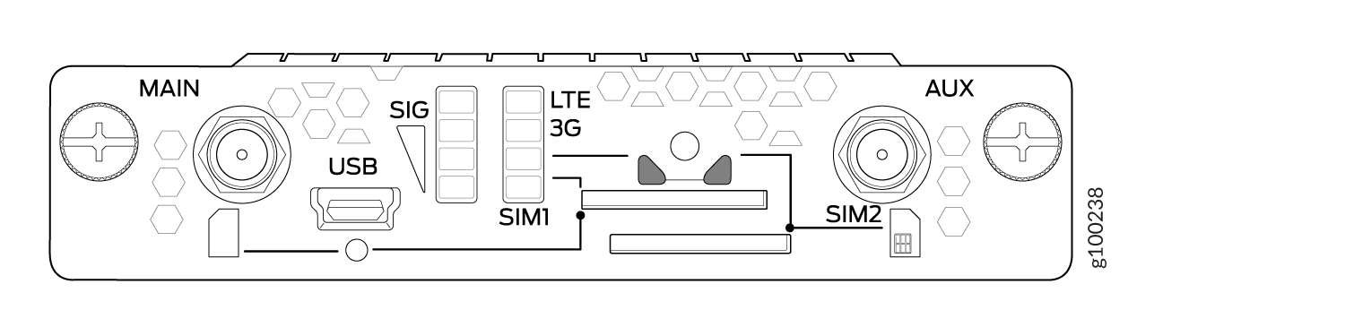
Figure 1 shows the front panel of the LTE Mini-PIM.
The LTE Mini-PIM ships with a SIM slot cover as shown in Figure 2.
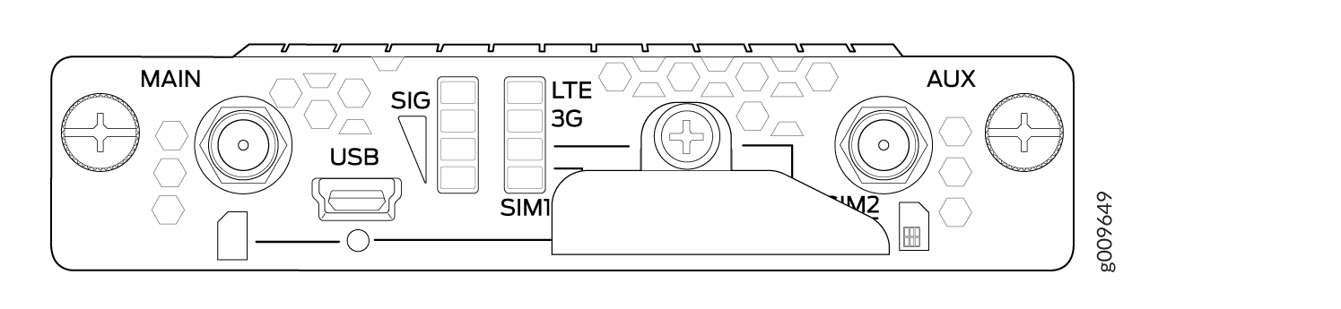
Table 1 lists the components on the front panel of the Mini-PIM.
Component |
Description |
|---|---|
Antenna connectors |
Two SubMiniature version A (SMA) connectors. |
Mini-USB port |
Mini-USB Type-B port for monitoring and troubleshooting. |
SIM slots |
Two slots, SIM1 and SIM2, for inserting the SIM cards. The LTE Mini-PIM supports mini, micro, and nano SIMs. The mini-SIM can be inserted directly in the SIM slot. To insert micro and nano SIMs, use the SIM adapters supplied with the Mini-PIM. The Mini-PIM is shipped with two SIM adapters. CAUTION: SIM cards are not hot-swappable. You must power off the services gateway before removing or inserting a SIM card. |
LEDs |
Indicate the status at a glance. For details on the LED indications, see LTE Mini-Physical Interface Module LEDs. |
The LTE Mini-PIM is not hot-swappable. You must power off the services gateway before removing or installing the Mini-PIM.
The LTE Mini-PIM supports two multi-band swivel-mount dipole antennas, which can be rotated 360 °. You can rotate the antennas and select the angle at which the signal strength is high.
Table 2 lists the specifications for the antenna.
Specification |
Value |
|---|---|
Part number |
EDA-2010-4G0R2-A2 (Vendor: MAG.LAYERS) |
Operating frequency range |
|
Voltage Standing Wave Ratio (VSWR) |
5 (maximum) |
Impedance |
50 ohm |
Radiation |
Omnidirectional |
Peak gain |
|
Input power |
1 W |
Polarization |
Linear, vertical |
Operating temperature |
–4° F (–20° C) to 149° F (65° C) |
Connector type |
SMA |
Length |
203 mm |
The antenna is connected to the services gateway through the magnetic antenna base. Table 3 lists the specifications for the antenna base.
Specification |
Value |
|---|---|
Part number |
BS-05SF-174-3M-0102 (Vendor: Chang Hong) |
Cable length |
3 m |
Connector type |
SMA |
Dimensions (H x W x L) |
29.50 mm x 73 mm x 73 mm |
Table 4 provides a summary of the different models of the Mini-PIM.
Model |
Mode |
Operating Region |
Frequency Band |
|---|---|---|---|
SRX-MP-LTE-AE |
|
|
For LTE:
For 3G (HSPA+):
|
SRX-MP-LTE-AA |
|
|
For LTE:
For 3G (HSPA+):
|
The Mini-PIM can be configured in three modes:
Always-on—The Mini-PIM connects to the 3G/4G network after booting. The connection is always maintained, as long as there are no network or connectivity problems.
Dial-on-demand—The Mini-PIM initiates a connection when it receives traffic.
Backup—The Mini-PIM connects to the 3G/4G network when the primary connection fails.
The LTE Mini-PIM supports the following wireless standards:
FCC Part 2
FCC Part 22
FCC Part 24, Part 27 and Part 90
RSS 129 and RSS 133, RSS 130, RSS 199, and RSS 139
RSS 132 and RSS 133
EN 301 511 GSM
EN 301 908-1
EN 301 908-2
The Certification and Engineering Bureau of Industry Canada (IC)
Radio Equipment (RE) Directive of the European Union
GCF
CTIA-PTCRB
LTE Mini-Physical Interface Module LEDs
Figure 3 shows the LEDs on the LTE Mini-PIM.
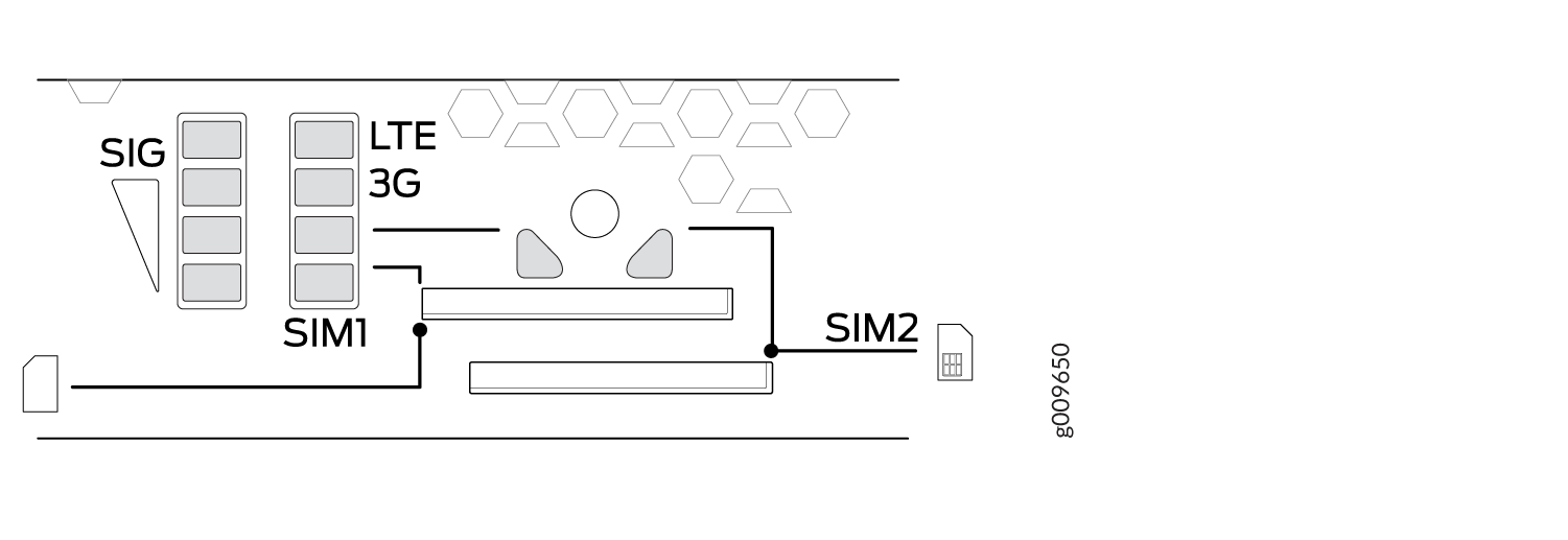
Table 5 lists the LEDs on the LTE Mini-PIM and their indications.
LED |
Description |
|---|---|
SIG (Received Signal Strength Indicator) |
Solid green (one bar)—Low signal strength (<= –99 dBm). |
Solid green (two bars)—Low signal strength (from –98 dBm to –87 dBm). |
|
Solid green (three bars)—Low signal strength (from –86 dBm to –76 dBm). |
|
Solid green (four bars)—High signal strength (>= –75 dBm). |
|
Unlit—No signal |
|
3G |
Solid green—3G connection is established. |
Blinking green—Connecting to a 3G network. |
|
LTE |
Solid green—LTE connection is established. |
Blinking green—Connecting to an LTE network. |
|
SIM1 |
Solid green—SIM1 is active. |
SIM2 |
Solid green—SIM2 is active. |
If all the LEDs are blinking, it indicates that firmware updates are in progress. Do not power off the services gateway before the updates complete.
LTE Mini-Physical Interface Module Hardware Specifications
Table 6 provides the hardware specifications for the LTE Mini-PIM.
Description |
Value |
|---|---|
Dimensions (H x W x L) |
0.80 in. x 3.75 in. x 5.9 in.(2.0 cm x 9.5 cm x 14.5 cm) |
Weight |
0.23 lb (0.106 kg) |
Connector type |
SMA |
Form factor |
Mini-PIM |
Environmental operating temperature |
32° F through 104° F (0° C through 40° C) |
Storage temperature |
-40° F through 158° F (-40° C through 70° C) |
Relative humidity |
5% to 90% noncondensing |
LTE Mini-Physical Interface Module Installation and Configuration
- Installing the LTE Mini-PIM
- Configuring the LTE Mini-PIM
- Configuring a Static Route on the Dialer Interface
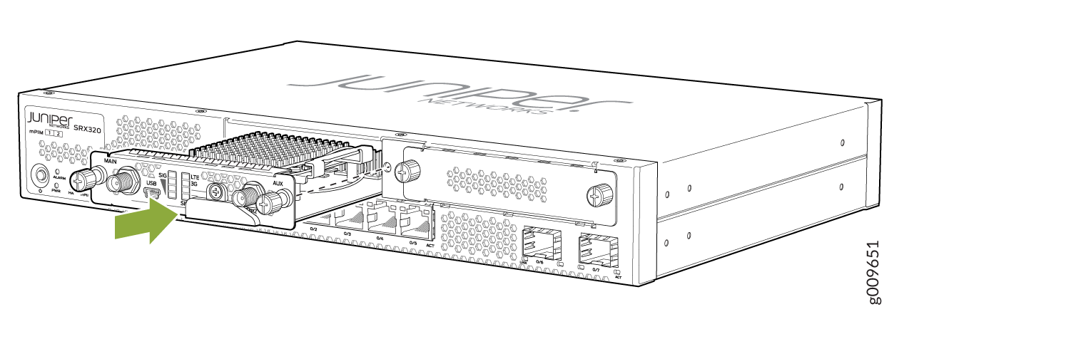
Installing the LTE Mini-PIM
The LTE Mini-PIM can be installed in any of the Mini-PIM slots on the services gateway.
You can install only one LTE Mini-PIM in a services gateway.
To install the LTE Mini-PIM in a services gateway:
- Slide the Mini-PIM in until it lodges firmly in the services
gateway. See Figure 4.Figure 4: Installing the LTE Mini-PIM
- Remove the SIM slot cover. Insert the SIM card into the
SIM slot, SIM 1.
You can use the other slot, SIM 2, for installing a secondary or backup SIM.
Note:When you insert SIM cards into the respective slots, make sure to orient the cards correctly. Insert SIM1 into its slot with the connector side (SIM card chip) facing down and the notch on the left. Insert SIM2 into its slot with the connector side facing up and the notch on the right. See Figure 5.
Figure 5: Inserting the SIM Card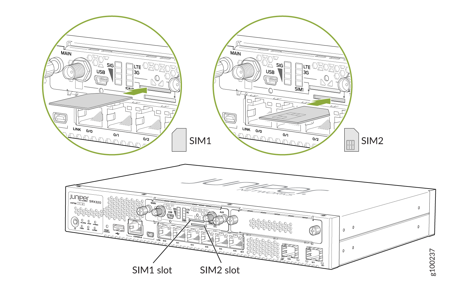
To remove a SIM card from its slot, press the edge of the card projecting out of the slot.
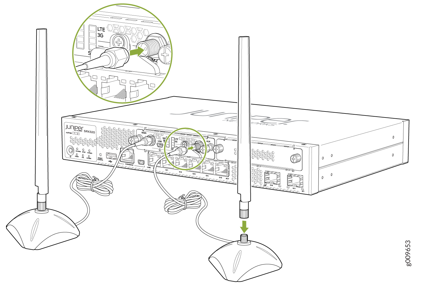
- Attach the antennas to the antenna base. Connect the cables
from each antenna base to the SMA connectors on the Mini-PIM. See Figure 6.Figure 6: Attaching the Antennas
The antenna base is magnetic and can be attached to the rack directly, if the rack is metallic. Else, you can mount the antenna base on the rack using the mounting brackets. See Figure 7.
Figure 7: Mounting the Antennas on a Rack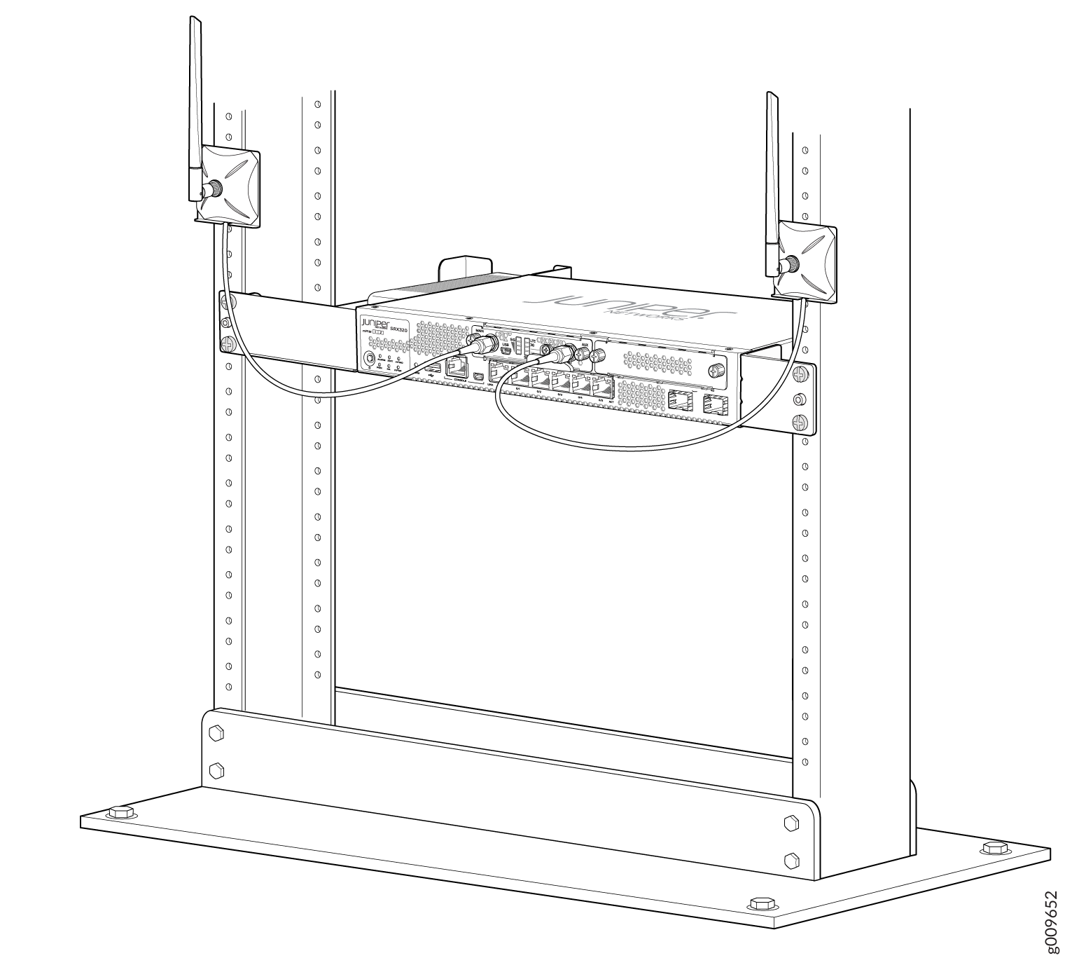 Note:
Note:For SRX320 Services Gateways, which can be mounted on a wall, the antennas can be mounted as shown in Figure 8.
Figure 8: Mounting the Antennas on a Wall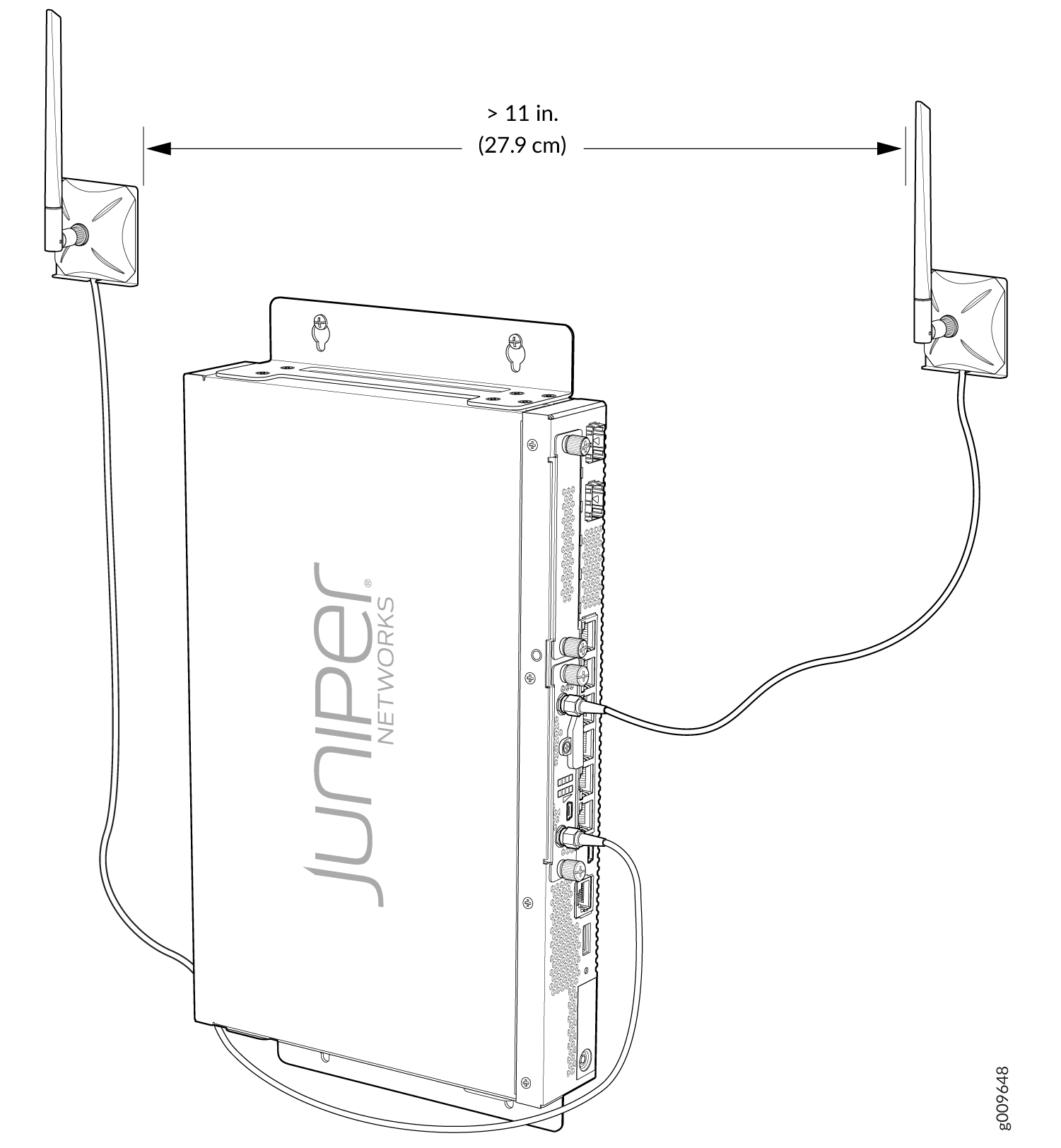
Configuring the LTE Mini-PIM
If a services gateway with factory-default settings is powered on with the LTE Mini-PIM installed in slot 1, the dialer interface is triggered to dial automatically. This functionality is applicable only if the Mini-PIM is installed in slot 1. If the Mini-PIM is installed in any other slot, then you will need to manually configure the cl-slot-number/0/0 interface to be associated with the dialer interface.
To configure the Mini-PIM:
Configuring a Static Route on the Dialer Interface
A static route enables the dialer interface to forward packets
to a specific destination other than the default route. Static routes
are manually configured and entered into the routing table. You can
configure a static route on the dialer interface by using the set interfaces dl0 unit 0 dialer-options route destination-ip-address command.
After you configure a static route, make sure that the route
appears in the routing table of the device by using the show
route command. Note that the static route appears in the routing
table only after the LTE Mini-PIM is connected to the network.
Sample output:
user@host> show route
inet.0: 10 destinations, 10 routes (10 active, 0 holddown, 0 hidden)
+ = Active Route, - = Last Active, * = Both
0.0.0.0/0          *[Access-internal/12] 4d 03:23:52, metric2 0
                    >  to 10.14.5.137 via dl0.0
10.22.22.22/32 *[Access-internal/12] 00:01:03, metric2 0
                    >  to 10.14.5.137 via dl0.0
Firmware Upgrade on the LTE Mini-Physical Interface Module
Mini-PIM Firmware Upgrade Using the CLI
To upgrade the firmware on the Mini-PIM, using the CLI:
When you upgrade the firmware on the Mini-PIM, the modem firmware is also upgraded.
Modem Firmware Upgrade Through Over-the-Air (OTA)
Over-the-Air (OTA) firmware upgrade enables automatic and timely upgrade of modem firmware when new firmware versions are available. The OTA upgrade can be enabled or disabled on the 4G/LTE Mini-PIM. OTA is disabled by default.