Virtual Chassis Overview (Juniper Mist)
Learn about the benefits of using a Virtual Chassis, the VC support on various switch models, and the design guidelines for deploying VC at your site.
The Virtual Chassis technology enables you to connect multiple individual switches together to form one logical unit and to manage the individual switches as a single unit. You can configure and manage a Virtual Chassis using the Juniper Mist™ portal. The switches you add to a Virtual Chassis are called members. In a Virtual Chassis setup, Virtual Chassis ports (VCPs) connect the member switches and are responsible for passing the data and control traffic between member switches.
A Virtual Chassis helps you mitigate the risk of loops. It also eliminates the need for legacy redundancy protocols such as spanning tree protocols (STPs) and Virtual Router Redundancy Protocol (VRRP). In core and distribution deployments, you can connect to the Virtual Chassis using link aggregation group (LAG) uplinks. These uplinks ensure that the member switches in a Virtual Chassis have device-level redundancy.
A Virtual Chassis can include from two to 10 switches. Such a physical configuration can provide better resilience if a member switch goes down. One possible disadvantage to combining several switches into a Virtual Chassis is that this configuration requires more space and power than a single device requires.
This video covers how Juniper Mist Cloud manages a virtual chassis, or VC. Up to 10 EX switches can be operated as one logical device and managed as a single chassis, simplifying network operations. This VC is made of two EX3400s.
You can see the port diagram showing more details, like the VC connect and roles, like backup and master. The EX switches are configured via templates, so here you can adjust the settings as needed. Additionally, for corner cases that cannot be satisfied in the UI, there is an option for CLI commands.
In the port profiles and configuration models video, we already configured VLANs, VLAN IDs, and port profiles, like an access point or camera. The profiles can be assigned to ports in the VC. For this setup, ports 19 and 20 are used as upstream links, with other ports mapped to other types of device profiles.
You can push configurations to a VC environment and see the switch data and activity in Switch Insights. You see a breakdown of CPU utilization, memory utilization, bytes, port errors, and power draw. The green color port shows its status of the port.
You can see the switches within the VC, or individually by toggling through the icons above the switch. Configuring and managing EX switches in a VC stack has never been more simple than with the Juniper MIScloud.
You can create a Virtual Chassis using the Form Virtual Chassis option on the Juniper Mist portal. The Form Virtual Chassis option applies only to the EX2300, EX4650, and QFX5120 switches as these switches don't have dedicated Virtual Chassis ports (VCPs). This option is not available to the EX3400, EX4100, EX4100-F, EX4300, and EX4400 switches as they come with dedicated VCPs. To create a Virtual Chassis with these switches, follow the procedure in this topic: Configure a Virtual Chassis Using EX3400, EX4100, EX4100-F, EX4100-H, EX4300, EX4000, or EX4400. However, the Modify Virtual Chassis workflow (see Manage a Virtual Chassis Using Mist) supports all the switches that Juniper supports Virtual Chassis on.
The table below shows the switch models along with the maximum number of member switches allowed in a Virtual Chassis configuration.
| Switch Model | Maximum Member Switches Allowed |
|---|---|
| EX2300 | 4 |
| EX4650 | 4 |
| EX3400 | 10 |
| EX4000 | 6 |
| EX4100 | 10 |
| EX4100-F | 10 |
| EX4100-H | 6 |
| EX4300 | 10 |
| EX4400 | 10 |
| QFX5120-32C, QFX5120-48T, QFX5120-48Y | 2 |
| QFX5120-48YM | 4 |
Mist supports only preprovisioned Virtual Chassis configuration. It doesn't support nonprovisioned configuration. The preprovisioned configuration lets deterministically control the roles and member IDs assigned to the member switches when creating and managing a Virtual Chassis. The preprovisioned configuration distinguishes member switches by associating their serial numbers with the member ID.
For more information, see Virtual Chassis Overview for Switches
Mixed and Non-Mixed Virtual Chassis
A Virtual Chassis that includes switches of the same model can operate as a non-mixed Virtual Chassis. However, a Virtual Chassis that includes different models of the same switch (for example, two or more types of EX Series switches) must operate in mixed mode because of architecture differences between the different switch models.
| Allowed Routing Engine Members | Allowed Linecard Members |
|---|---|
| EX4300 | EX4300 and EX4600 |
| EX4300-48MP | EX4300-48MP and EX4300 (excludes EX4600) |
|
EX4600 |
EX4600 and EX4300 (excludes EX4300-48MP) |
For more information about the combination of switches that a mixed or a non-mixed Virtual Chassis configuration supports, see Understanding Mixed EX Series and QFX Series Virtual Chassis.
Design Considerations for Virtual Chassis
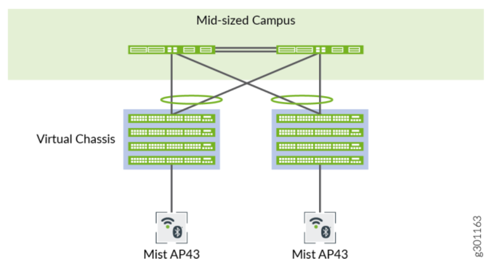
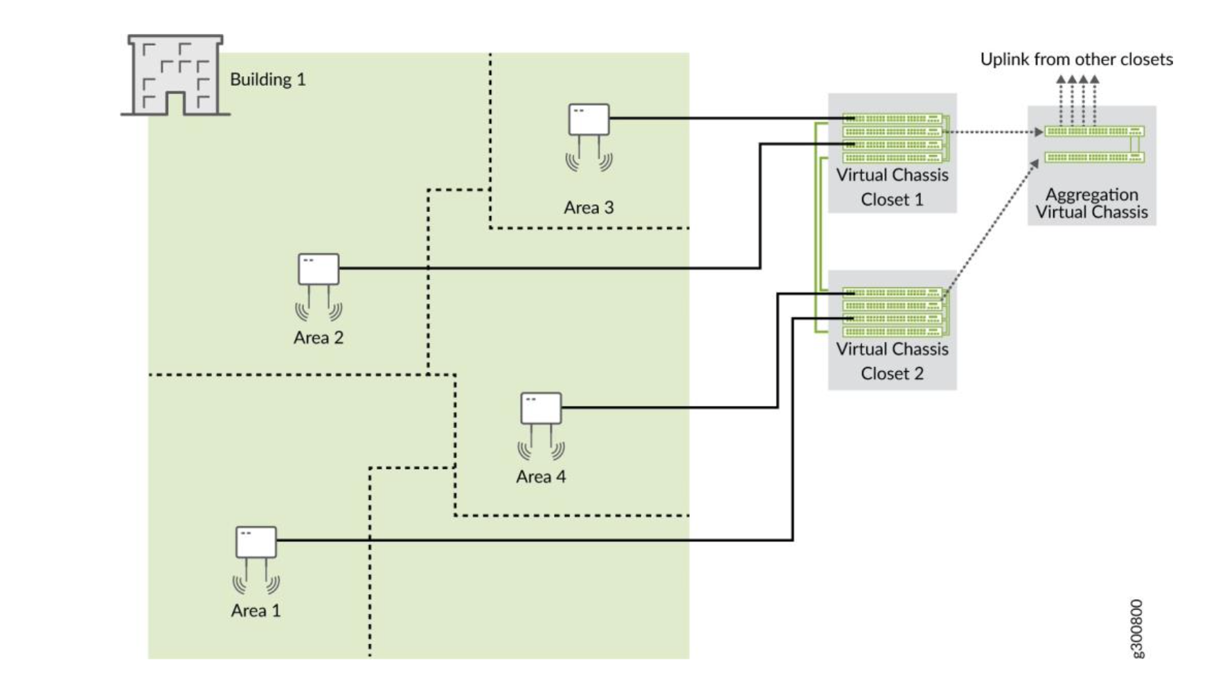
We recommend that you physically distribute your Juniper access points (APs) across the network operations center (NOC) floor. This helps you connect each switch in a virtual stack to a different AP. Doing so provides better redundancy. This design also helps in handling hardware failures related to power supply.
For example, you can use one of the following two options if you want to deploy a solution that includes 96 ports:
-
Use two EX4300-48P switches, with one switch serving as the primary and the other as the backup. This option is cost effective and ensures a compact footprint. The main disadvantage of this option is that a failure of one switch can negatively affect 50 percent of your users.
-
Use four EX4300-24P switches, with one switch serving as the primary, one as the backup, and the remaining two switches as linecard members. This option provides a better high availability because any failure of one switch affects only 25 percent of users. A switch failure does not necessarily affect the uplinks (if the failed switch did not include any uplinks). This option requires more space and power.
Regardless of the options you choose, we recommend that you do the following:
-
Configure the primary and backup switches in the Virtual Chassis in such a way that they are in different physical locations.
-
Distribute the member switches of the Virtual Chassis in such a way that no more than half of the switches depend on the same power supply or any single point of failure.
-
Space the member switches evenly by a member hop in the Virtual Chassis.