Use Custom Options to Configure Secure Edge Connector
Use custom provider option to configure tunnel provisioning or to support site-to-site VPN.
Juniper Mist™ offers custom options for tunnel provisioning. With minimal configuration, your WAN Edge device can establish connections to the Secure Service Edge (SSE) using either IPsec or GRE protocols.
The Custom option gives you the flexibility to specify the exact encryption and authentication algorithm used to best suit your deployment needs.
For example, you can set up site-to-site VPN using custom options for tunnel provisioning. A site-to-site VPN is a secure, software-defined network connection that links two or more remote sites over the internet. Enterprises use this type of VPN to securely and efficiently connect branch offices, data centers, or other remote locations.
Configure Tunnel Provisioning
Before You Begin: Ensure you have the local and remote network account details on hand.
To configure a tunnel from the WAN Edge to SSE:
-
Scroll to the Secure Edge Connectors section, click
Add Providers, and enter the settings in the side
panel:
Table 1: Add Provider Settings (IPsec Protocol Example) Field Value Name Enter the name of the service. Provider Select Custom. Remote Networks Select an existing Network or create a network. Protocol Select IPsec or GRE. Then enter the settings for the selected protocol. Local ID (IPsec only) Enter the login ID for the local account. Pre-Shared Key (Clear Text) (IPsec only) Enter the preshared key (PSK) for the local account. The length of the PSK must be between 6-255 characters. IP or Hostname Enter the IP address or hostname. Source IPs Enter the Source IP address of the tunnel. Probe IPs Enter the Probe IP address. You can use any well-known IP (Example: 8.8.8.8). Remote IDs (IPsec only) Provide the login ID of the remote account. WAN Interface Add one or more WAN interfaces to provision primary and secondary tunnels. If you add multiple WAN interfaces, the first interface takes priority. If the first interface is down, then system uses the second interface to establish the tunnel. When you click Add Interface, choose from the list of WANs that have been configured for the selected template, hub profile, or device.
IKEv2 proposal (IPsec only) Retain default values or click Add Proposal. Then enter the settings. IPsec Proposals Click Add Proposal. For Encryption Algorithm, Authentication Algorithm, and DH Group, keep the default values, or select new ones. Then click the blue checkmark in the Add Proposal title bar. Lifetime (IPsec Only) Enter a value between 180 to 86400 seconds. 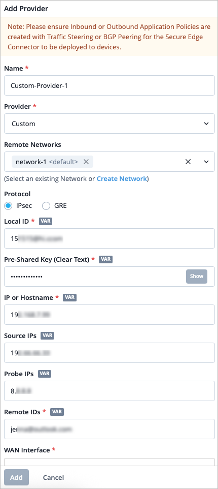
-
Scroll down to the BGP section, click Add BGP Group,
and enter the settings.
Tips:
-
For the Peering Network, select SEC Tunnel, then select the same provider that you created in Secure Edge Connectors in step 2.
-
For Local AS, enter the AS number or non-default AS for the WAN Edge.
You can use Table 2 to guide you as you enter the settings. This example demonstrates a BGP-over-GRE configuration. Users can also configure BGP-over-IPsec in this context.
-
Table 2: BGP Group Settings for GRE Protocol Field Value Name Give the BGP group a name, such as "BGP-over-GRE". Peering Network Choose SEC Tunnel, and then select the tunnel you configured in step 2 above. BFD Choose Disabled. Type Choose External. Local AS Enter the number of the AS you are using, for example, 65000. Hold Time Specify a time, in seconds such as 90. Graceful Restart Time Specify a time, in seconds, such as 120. 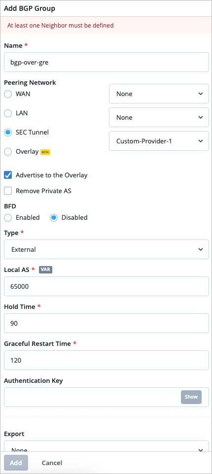
-
In the Neighbors section, click Add Neighbor. Add the IP Address and the Neighbor AS value.
-
Optionally, you can add a BGP policy for import or export of routes.
For help with other BGP settings, see BGP. -
-
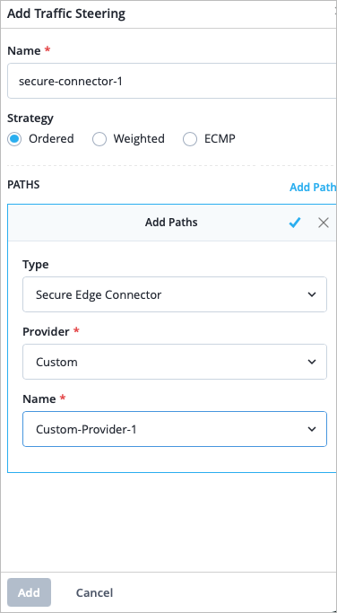
Scroll to the Traffic Steering section, click
Add Traffic Steering, and enter the settings. Use
the table below to guide you. See Traffic Steering Rules.
Table 3: Traffic Steering Settings Field Value Name Enter the name of the traffic steering rule. Strategy Select a strategy. You can configure the traffic steering profile with any strategy (Ordered/Weighted/ECMP), based on your topology and configuration. Add Path Click Add Paths and enter the following details. - Type—Select Secure Edge Connector.
- Provider—Select Custom.
- Name—Select the name of the Custom provider you created in Step 2.
-
Scroll to the Application Policy section and click
Add Application Policy. Use the table below to
guide you.
Table 4: Application Policy Settings Field Value Name Enter a name for the application policy. Network/User Include the remote network you used to create the Custom provider in step 2. We put this network in the application policy to allow inbound access from the Secure Edge Connector. Action Select an action of Allow for the traffic to reach its destination. Application/Destination Select the applications that you want the Network/User to have access to. Traffic Steering Select the traffic steering policy you created in step 6 so that traffic can use the secure edge tunnel to reach its destination. 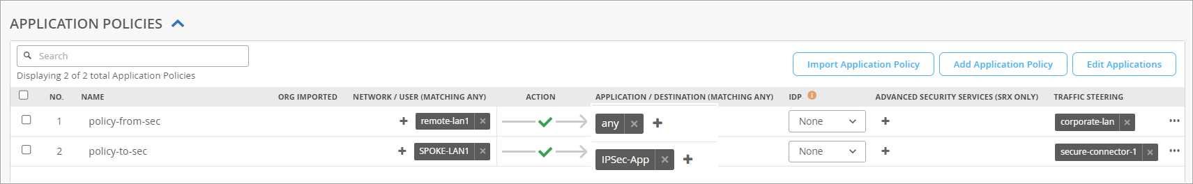
Verify Juniper Secure Edge Tunnels
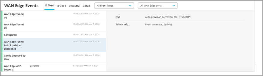
On the Mist portal, you can verify the established tunnel's details in WAN Edges > WAN Edges, then click WAN Edge Insights. You should see the WAN Edge Tunnel Auto Provision Succeeded event under WAN Edge Events.
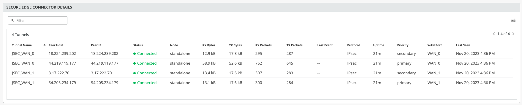
Get the established tunnel's status details by navigating to WAN Edges > WAN Edges, then scroll down to the Secure Edge Connector Details section.
To verify the BGP over GRE session you created, you can use the WAN Edge testing tools, navigate to WAN Edges > WAN Edges > Click the WAN Edge > Utilities > Testing Tools
- Open the BGP tab > Summary tab > Show Summary. You can also verify the tunnel in the Routes tab > Show Routes.
You can view the tunnel statistics under Probe Stats on the WAN Edge Insights page. To view an example of this, see Tunnel Statistics.