Help us improve your experience.
Let us know what you think.
Do you have time for a two-minute survey?
Help us improve your experience.
Let us know what you think.
Do you have time for a two-minute survey?
SUMMARY Learn how to configure captive portal for Web authentication and firewall user authentication using J-Web.
What Is Captive Portal?
Captive portal is a method of authenticating devices that need to connect to a network. On an SRX Series devices, you can enable captive portal to redirect Web browser requests to a login page that prompts you to enter your username and password. After successful authentication, you can proceed with the original page request and subsequent network access.
What Is Web Authentication?
With a Web authentication method, you point a browser to an IP address on a device that is enabled for Web authentication. This action initiates an HTTPS session on the IP address that hosts the Web authentication feature on the device. The device then prompts you to enter your username and password, and the result is cached on the device. When the traffic later encounters a Web authentication policy, your access is allowed or denied based on the previous Web authentication results.
You can use other authentication methods as well, but we will not cover those methods in this document. However, we describe each of those methods in brief:
Pass-through authentication—Pass-through user authentication is a form of active authentication. In this method, the device prompts you to enter a username and password. If authentication validates your identity, you are allowed to pass through the firewall and access the requested resources.
Pass-through with web-redirect—When using this authentication method for HTTPS client requests, you can use the web-redirect feature to direct your requests to the device's internal webserver. The webserver sends a redirect HTTPS response to the client system, directing it to reconnect to the webserver for user authentication. The interface that the client’s request arrives at is the interface on which the redirect response is sent.
What Is Firewall User Authentication?
A firewall user is a network user who must provide a username and password for authentication when initiating a connection across the firewall. Junos OS enables administrators to restrict or to permit firewall users’ access to protected resources (in different zones) behind a firewall based on their source IP address and other credentials. After defining the firewall users, you can create a policy that requires the users to authenticate using one of the three authentication methods (Web, pass-through, or pass-through with web-redirect).
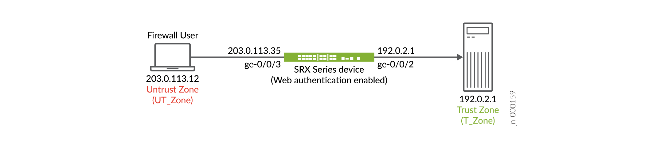
Here’s a sample topology (see Figure 1), which comprises:
A firewall user’s device that acts as a client.
An SRX Series device that has access to the Internet.
A network device that acts as an HTTPS server.
In this sample topology, you’ll use J-Web on the SRX Series device to do the following tasks:
The values used to configure the sample topology are only examples.
Step |
Action |
|---|---|
1 |
Create a logical interface on ge-0/0/3, assign it the IP address 203.0.113.35, and enable Web authentication. Note: In this example, the firewall user system IP address is 203.0.113.12, which is in the same subnet as 203.0.113.0/24. Create a logical interface on ge-0/0/2 and assign it the IP address 192.0.2.1. Note: In this example, the HTTPS server IP address is 192.0.2.1. |
2 |
Create an access profile (FWAUTH) and define local authentication services. |
3 |
Configure Web authentication settings to display the successful login message. |
4 |
Create an untrust (UT_ZONE) and a trust (T_ZONE) zones and assign the ge-0/0/3 and ge-0/0/2 interfaces, respectively. |
5 |
Configure captive portal for Web authentication and firewall user authentication in the security policy rules (FWAUTH-RULE). |
6 |
Verify that the configured values work for a firewall user:
|
The values used to configure the sample topology are only examples. You can change any details necessary to match your network configuration.
Ensure that the SRX Series device you use in this example runs Junos OS Release 21.4R1 or later.
Ensure that your device has the required certificates installed to allow authentication. In this example, we'll use cert1, a self-signed certificate.
In this step, you’ll do the following tasks:
For the ge-0/0/3 interface on the SRX Series device:
Create a logical interface for an untrust zone.
Assign the IPv4 address 203.0.113.35 to the interface.
You’ll use the same IP address for enabling captive portal.
Enable HTTPS on the interface for Web authentication.
For the ge-0/0/2 interface on the SRX Series device:
Create a logical interface for a trust zone.
Assign the IPv4 address 192.0.2.1 to the interface.
You are here (in the J-Web UI): Network > Connectivity > Interfaces
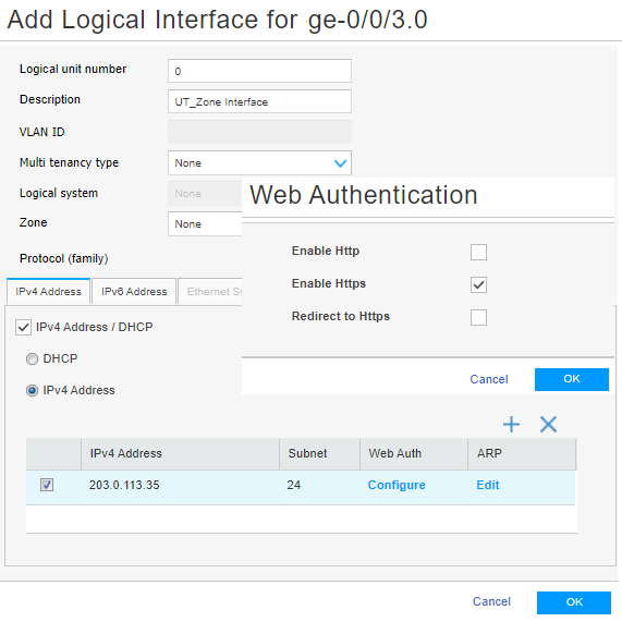
To create a logical interface for an untrust zone and to enable Web authentication:
Field |
Action |
|---|---|
Logical unit number |
Type 0. |
Description |
Type UT_Zone Interface. |
VLAN ID |
This field is not editable. |
Multi tenancy type |
Select None from the list. |
Logical system |
This field is not editable. |
Zone |
Select None from the list. In a later step, we'll create an untrust zone (UT_ZONE) and assign the ge-0/0/3 interface to it. See Step 4: Create Security Zones and Assign Interfaces to the Zones. |
Protocol (family) - IPv4 Address |
|
IPv4 Address / DHCP |
Select the check box to enable the IPv4 Address/DHCP configuration. |
IPv4 Address |
Select IPv4 Address. Then, click + and enter the following details:
|
To create a logical interface for a trust zone:
Select ge-0/0/2 and then select Create > Logical Interface on the upper-right corner of the Interfaces page.
The Add Logical Interface for ge-0/0/2.0 page appears.
Specify the following details:
Field |
Action |
|---|---|
Logical unit number |
Type 0. |
Description |
Type T_Zone Interface. |
VLAN ID |
This field is not editable. |
Multi tenancy type |
Select None from the list. |
Logical system |
This field is not editable. |
Zone |
Select None from the list. In a later step, we'll create a trust zone (T_ZONE) and assign the ge-0/0/2 interface to it. See Step 4: Create Security Zones and Assign Interfaces to the Zones. |
VLAN ID |
This field is not editable. |
Protocol (family) - IPv4 Address |
|
IPv4 Address / DHCP |
Select the check box to enable the IPv4 Address/DHCP configuration. |
IPv4 Address |
|
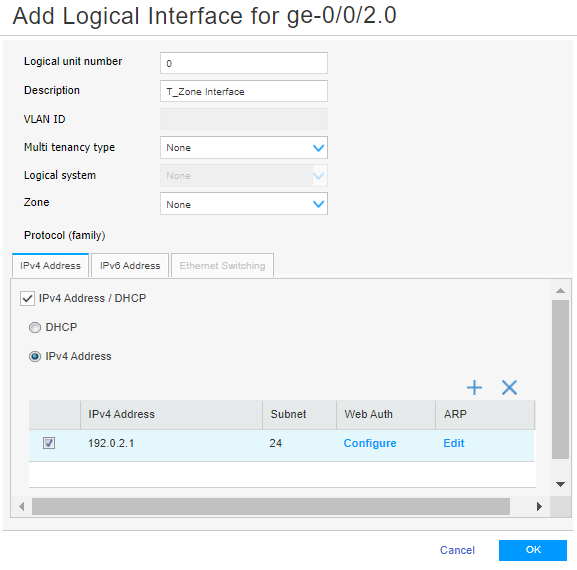
Click OK to save the changes.
Good job! You’ve created a logical interface on ge-0/0/2 with IP address 192.0.2.1 for the HTTPS server.
Click Commit (at the right-side of the top banner) and select Commit configuration to commit the changes now.
The successful-commit message appears.
You can also choose to commit all configuration changes at once, at the end of Step 5: Enable Web or Firewall User Authentication for Captive Portal in the Security Policy.
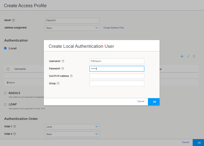
Let’s create an access profile to define local authentication services. You will use this access profile in Web authentication settings and security policies.
You are here (in the J-Web UI): Security Services > Firewall Authentication > Access Profile
To create an access profile:
Field |
Action |
|---|---|
Name |
Type FWAUTH. |
Address Assignment |
(Optional) Select None from the list. You can select an address pool from the list. You can also add a new address pool by clicking Create Address Pool and providing the required values. |
Authentication |
|
Local |
|
Authentication Order |
|
Order 1 |
Select Local from the list. |
Order 2 |
By default, None is selected. Leave as is. |
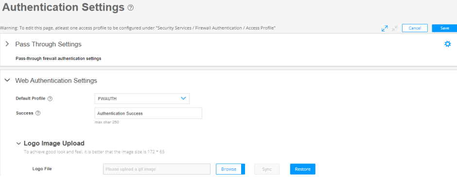
We’ll now assign the created access profile, define a successful-login message, and upload the logo image. This image is used for both Web authentication and captive portal.
You are here (in the J-Web UI): Security Services > Firewall Authentication > Authentication Settings
To configure Web authentication settings:
Click Logo Image Upload.
Click Browse for uploading a logo file.
Select a logo image and then click OK.
For a good logo, the image must be in the .gif format and the resolution must be 172x65.
Click Sync to apply the logo.
The uploaded image will now appear on the captive portal login page or the Web authentication login page.
You create a security zone to define one or more network segments that regulate inbound and outbound traffic through policies.
We’ll now separately create:
An untrust zone (UT_ZONE) and assign the ge-0/0/3 interface to it.
A trust zone (T_ZONE) and assign the ge-0/0/2 interface to it.
You are here (in the J-Web UI): Security Policies & Objects > Zones/Screens
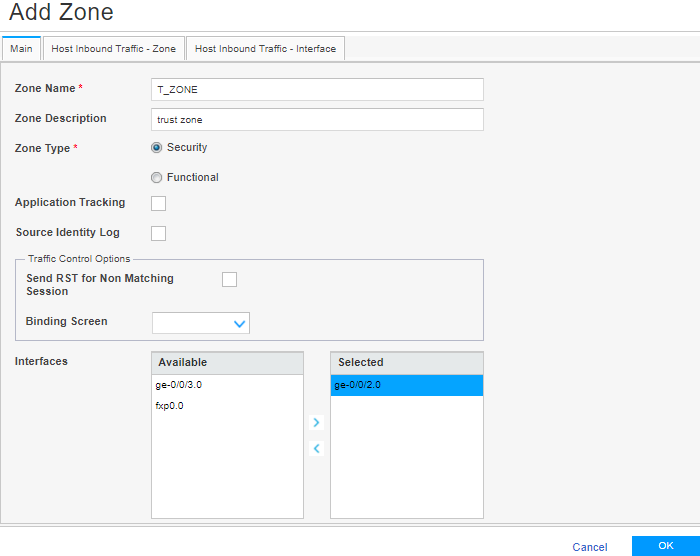
To create UT_ZONE (untrust zone) and T_ZONE (trust zone) and to assign the defined interfaces to the zones:
Field |
Action |
|---|---|
Main |
|
Zone name |
|
Zone description |
|
Zone type |
Select Security. |
Application Tracking |
Leave as is. |
Source Identity Log |
Leave as is. |
Traffic Control Options |
Leave as is. |
Interfaces |
|

Field |
Action (Sample Value) |
|---|---|
Host Inbound Traffic - Zone |
Leave as is. |
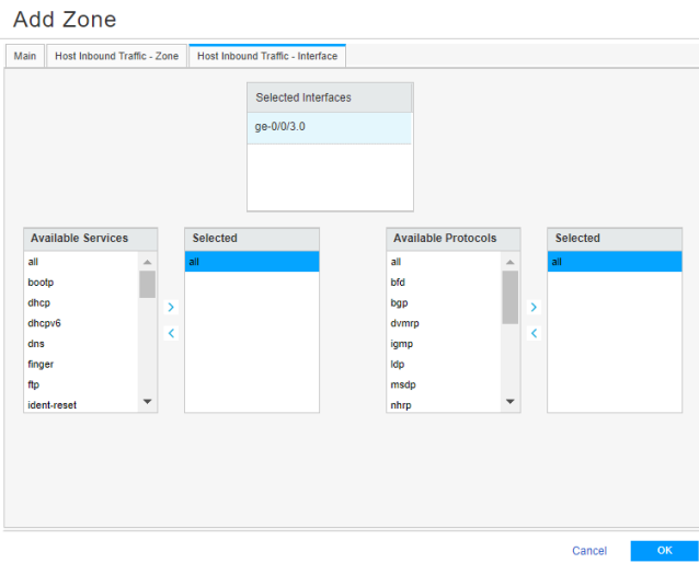
Host Inbound Traffic - Interface |
|
Selected Interfaces |
|
Available Services |
Select all from the Available Services column and click the right arrow to move it to the Selected column. |
Available Protocols |
Select all from the Available Protocols column and click the right arrow to move it to the Selected column. |

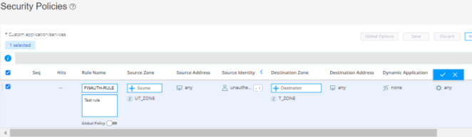
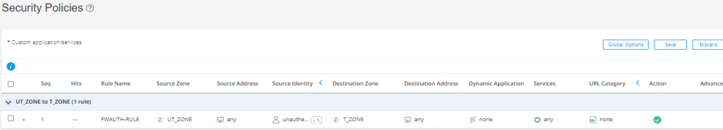
We’ll now enable captive portal in the security policy rules to redirect a client HTTPS request to the internal HTTPS server of the device.
You are here (in the J-Web UI): Security Policies & Objects > Security Policies
To configure security policy rule for captive portal:
Field |
Action |
|---|---|
Rule Name |
|
Name |
Type FWAUTH-RULE. |
Description |
Type Test rule. |
Source Zone |
|
+ |
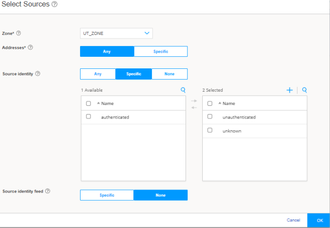
Click + to add a source zone. The Select Sources page appears. |
Select Sources |
Specify the following details:
|
Destination Zone |
|
+ |
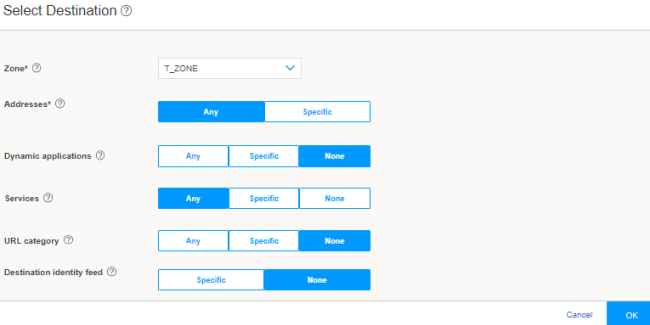
Click + to add a destination zone. The Select Destination page appears. |
Select Destination |
Specify the following details:
|
Action |
Select Permit. |
Advanced Services |
Leave as is. |
Rule Options |
|
+ |
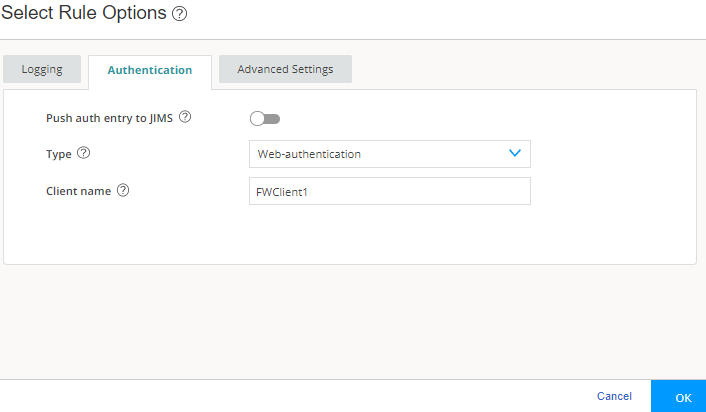
Click + to select rule options. The Select Rule Options page appears. |
Logging |
Leave as is. |
Authentication Note: Use this configuration for Web authentication only. |
Specify the following details:
|
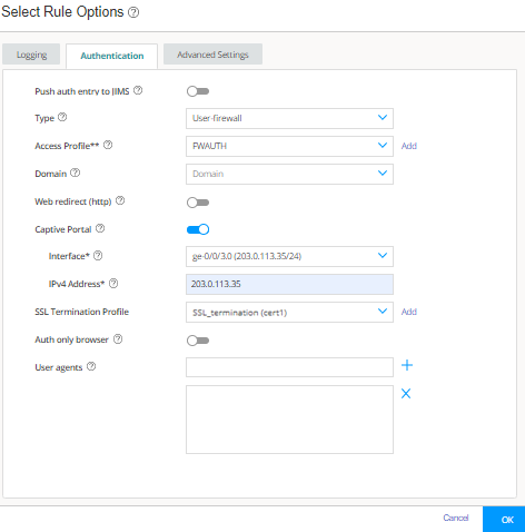
Authentication Note: Use this configuration for firewall user authentication only. |
Specify the following details:
|
 on the right-side of the row
after you're done with the configuration.
on the right-side of the row
after you're done with the configuration.Slide the horizontal bar backward if the inline tick and cancel icons are not available when creating a new rule.
The final step! Let’s see wether your configurations works for a firewall user:
For Web authentication, you’ll successfully authenticate using https://203.0.113.35. This is the same IPv4 address that you configured in Step 1: Create a Logical Interface and Enable Web Authentication.
For firewall user authentication, you’ll successfully authenticate using https://203.0.113.35 and then get redirected to https://192.0.2.1 for accessing the HTTPS server. These are the same IPv4 addresses that you configured in Step 1: Create a Logical Interface and Enable Web Authentication.
To verify the Web authentication configuration:
Type https://203.0.113.35 in your Web browser.
The Firewall Authentication login page appears.
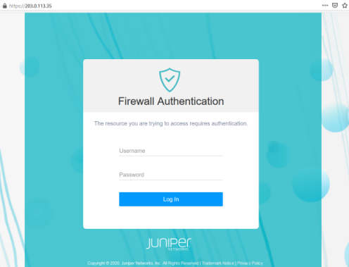
Type the following credentials, and then click Log In.
Username—FWClient1
Password—$ABC123
Congratulations! You are successfully authenticated. You can also see the success message Authentication Success that you configured.
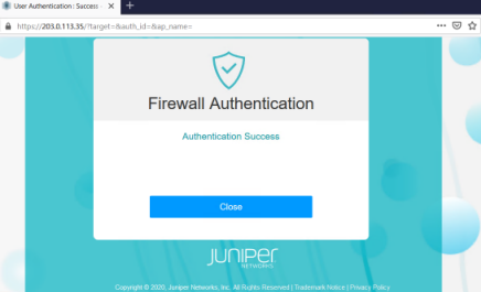
Click Close.
To verify firewall user authentication:
Type https://192.0.2.1 in your Web browser.
You are redirected to https://203.0.113.35 for Web authentication.
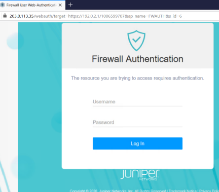
Type the following credentials, and then click Log In.
Username—FWClient1
Password—$ABC123
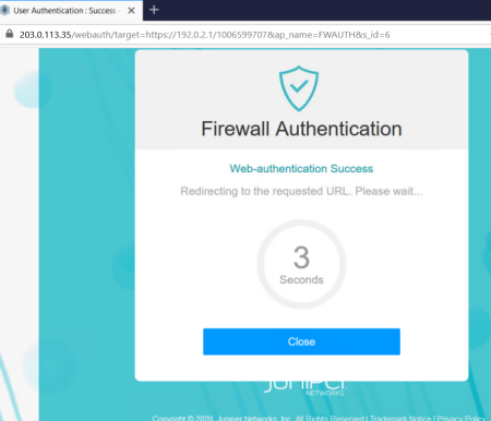
Congratulations! You are successfully authenticated. Soon, you’ll be redirected to https://192.0.2.1, and you’ll be able to access the HTTPS server.
To keep going, visit the J-Web for SRX Series Documentation page in the Juniper TechLibrary.