Configuration Walkthrough
Apstra Configuration for Configuring SRX4600
This JVDE walks through the steps to create connectivity between the SRX4600 and 3-stage data center fabric Spine switches using Juniper Apstra. For the purposes of this JVDE, two SRX4600 are connected to each Spine switch. In the current Apstra version, SRX4600 is not supported under device profiles. Therefore, the two SRX4600 are added as external generic servers connected to the Spines and must be added as a Remote EVPN Gateway (also known as external Gateway). Hence Apstra does not manage the SRX4600.
For high availability, the SRX devices are configured as MNHA. For more information on MNHA refer to the SRX user guide or to the techpost that provides different architecture deployments.
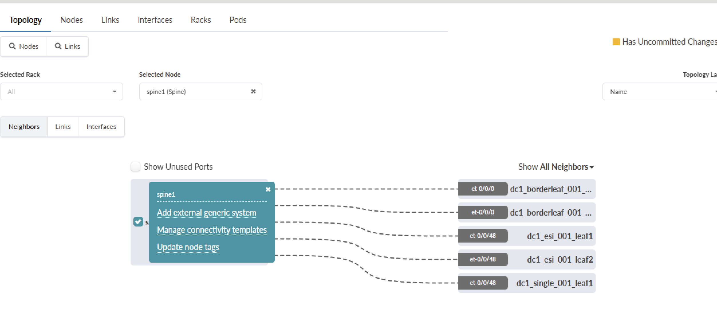
Create Generic Server for SRX4600 and add links
The process discussed here covers configurations for the first SRX4600 as the same steps apply to the second SRX4600. For more information on adding SRX4600 as an external generic system refer to the Apstra User guide.
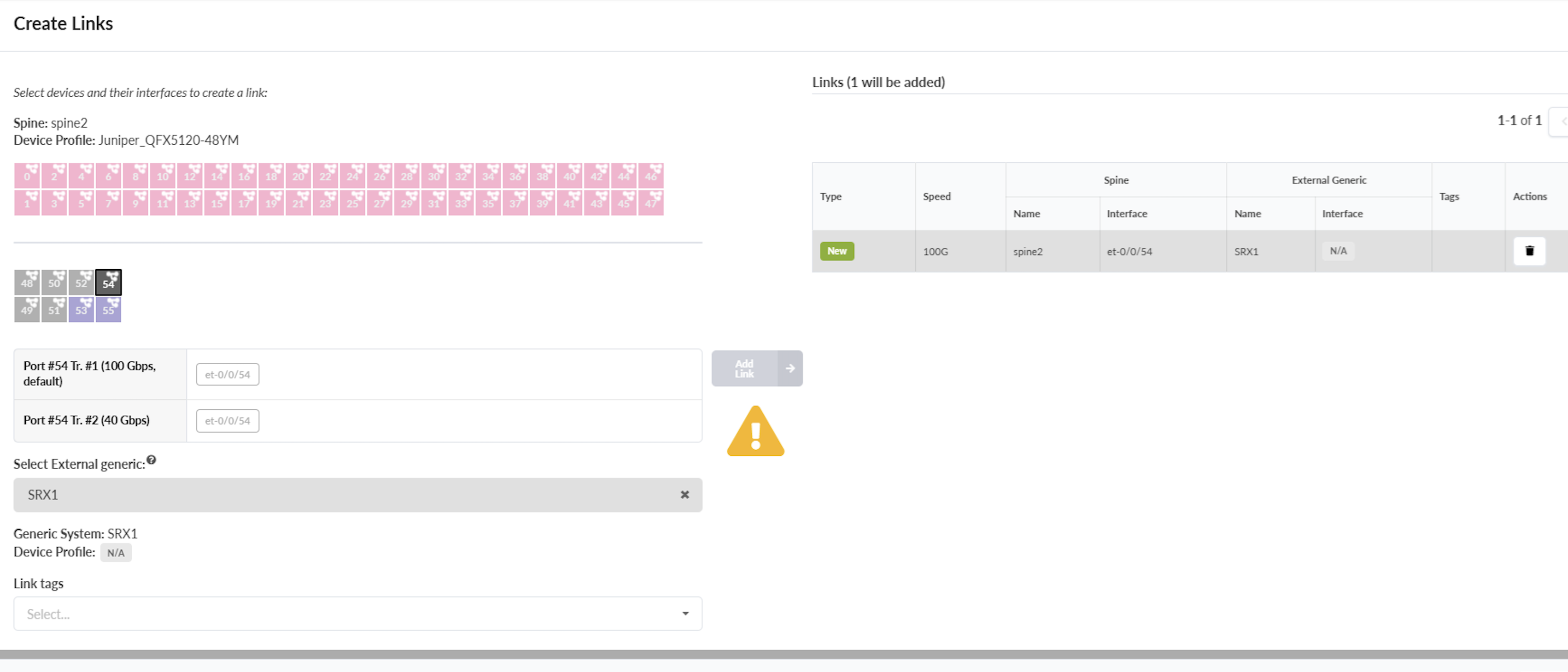
After creating a generic server for SRX devices, add links to each Spine to create physical connectivity to the spine. See the Apstra guide for adding links. A link to Spine 1 and another link to Spine-2 is created as shown below in Figure 2 and Figure 3.
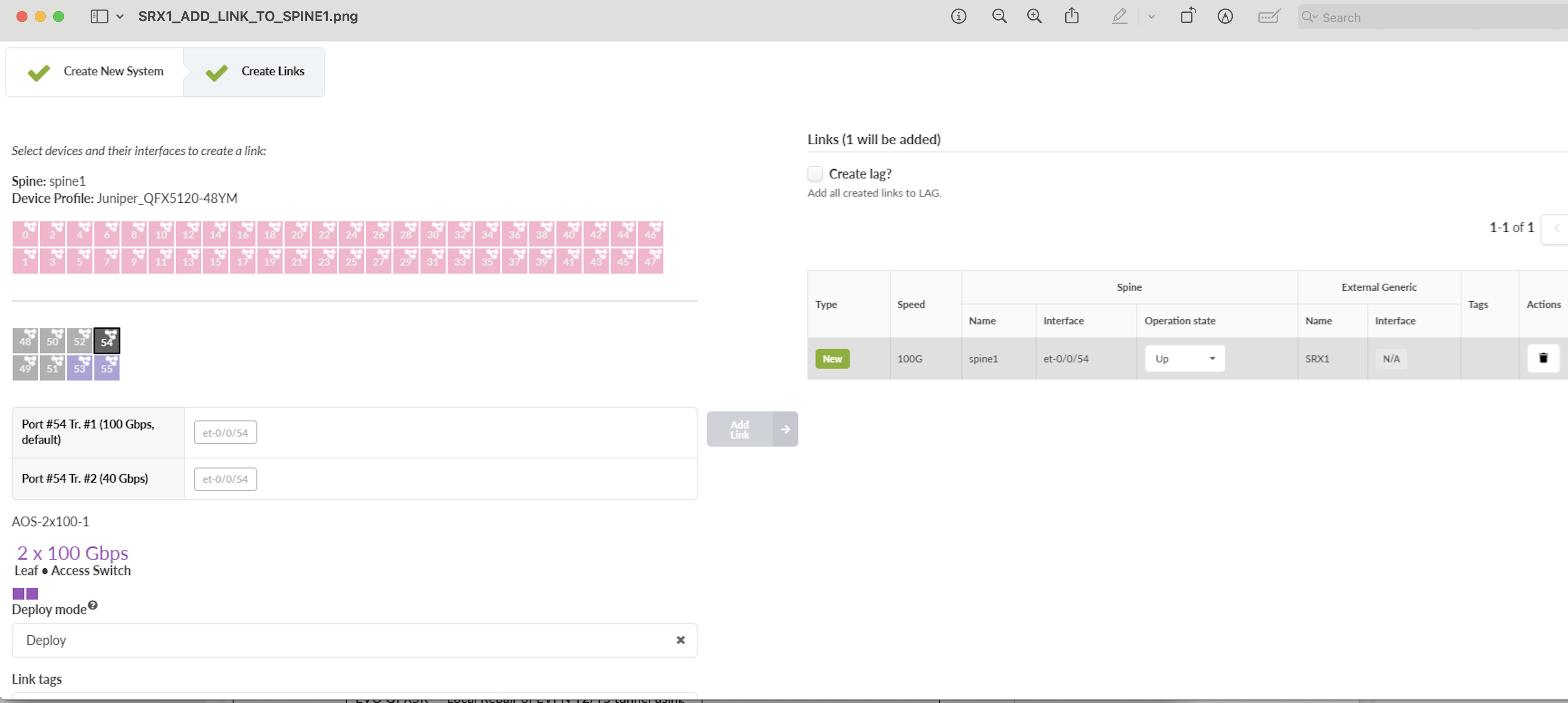
Ensure that the cabling correctly reflects the interface names for Spine switches. Navigate to Blueprint > {Your Blueprint} > Staged > Physical and then click on link and edit cabling.
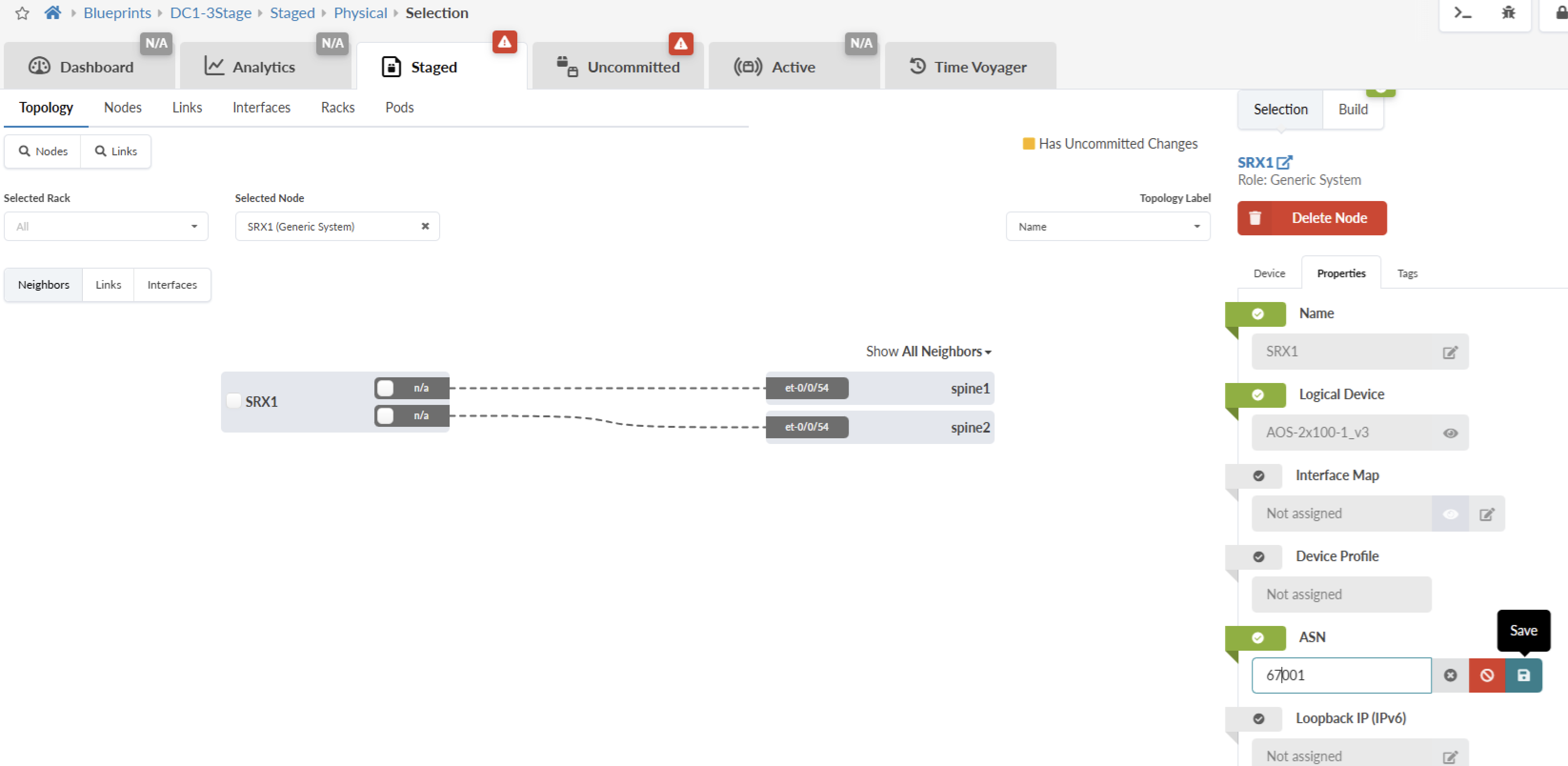
Assign ASN Numbers to SRX4600
Next assign ASN numbers to the SRX4600 as shown in Figure 4.
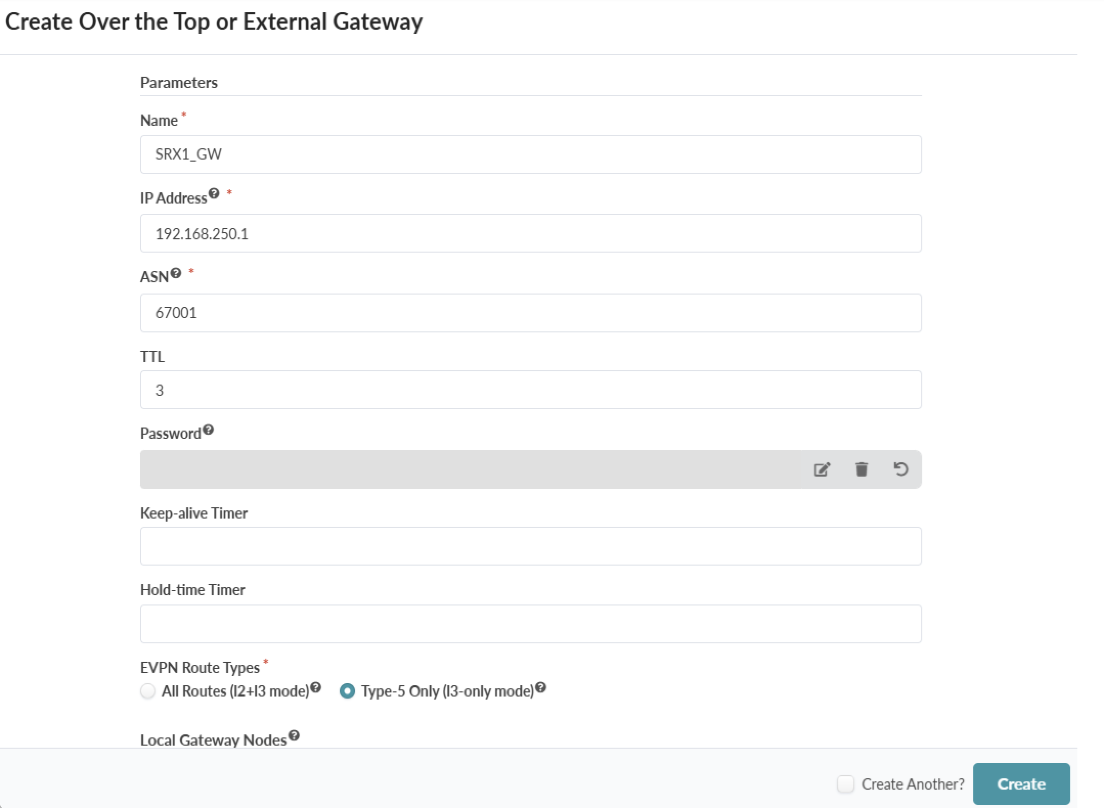
SRX Device as Remote EVPN Gateway (External Gateway) in Apstra
The SRX devices are added as external gateways/Remote EVPN Gateway in Apstra. Refer the Apstra guide for information on the External Gateway/Remote EVPN Gateway. Apstra guide also covers the steps to add Remote EVPN Gateway to extend the control plane.
From Blueprints > {Blueprint name} > Staged > DCI navigate to Over the top or External Gateways and click on Create over the top or External Gateway and create external gateway.
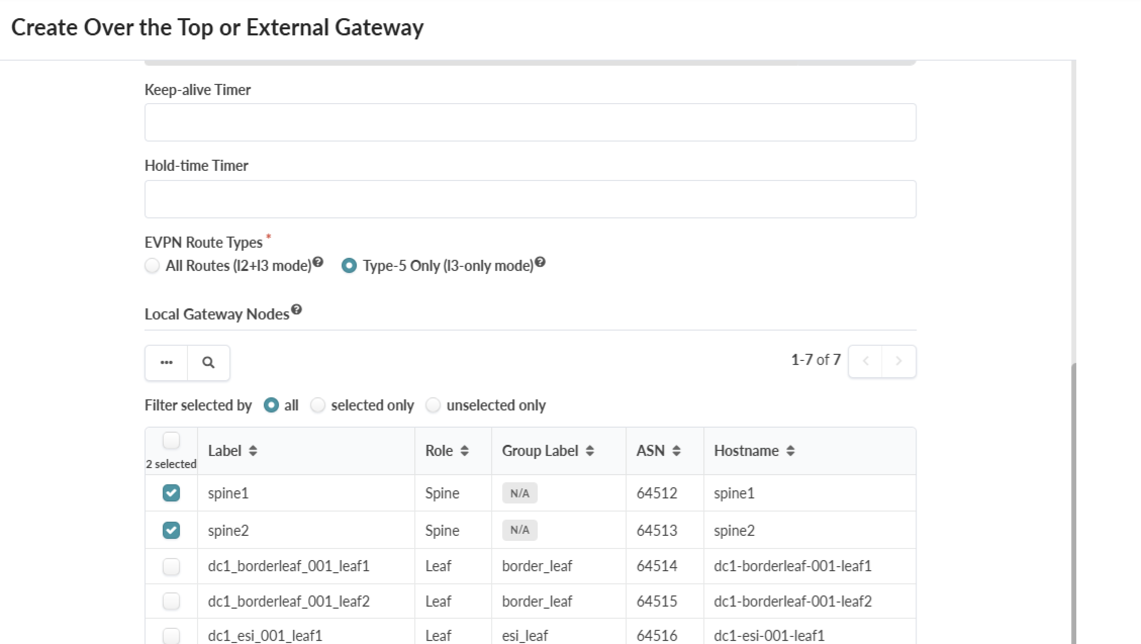
Assign the SRX gateway to the Spines as shown in Figure 6.
Create Underlay Connectivity from SRX Device to the Spine
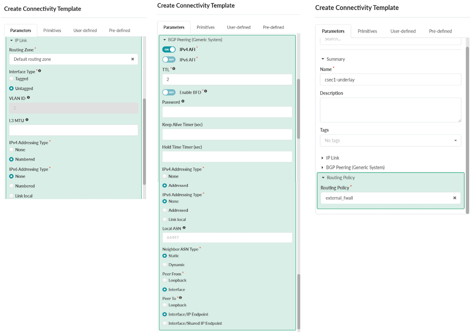
Use the Create Connectivity Template in Apstra to create the underlay connectivity by configuring the routing connections from each SRX device to the different Spine switches. To create the underlay connectivity, assign the primitive types for IP link, BGP Peers and Routing Policy in Apstra Connectivity templates. For more information on Connectivity Templates see the Apstra Guide.
As shown in Figure 7, connectivity template is created and the Default Routing Zone is used for VRF to the SRX devices, BGP peering is created between SRX device and Spine, and the IPV4 address is used to setup for connectivity. Next the Routing policy is also assigned for route exchange.
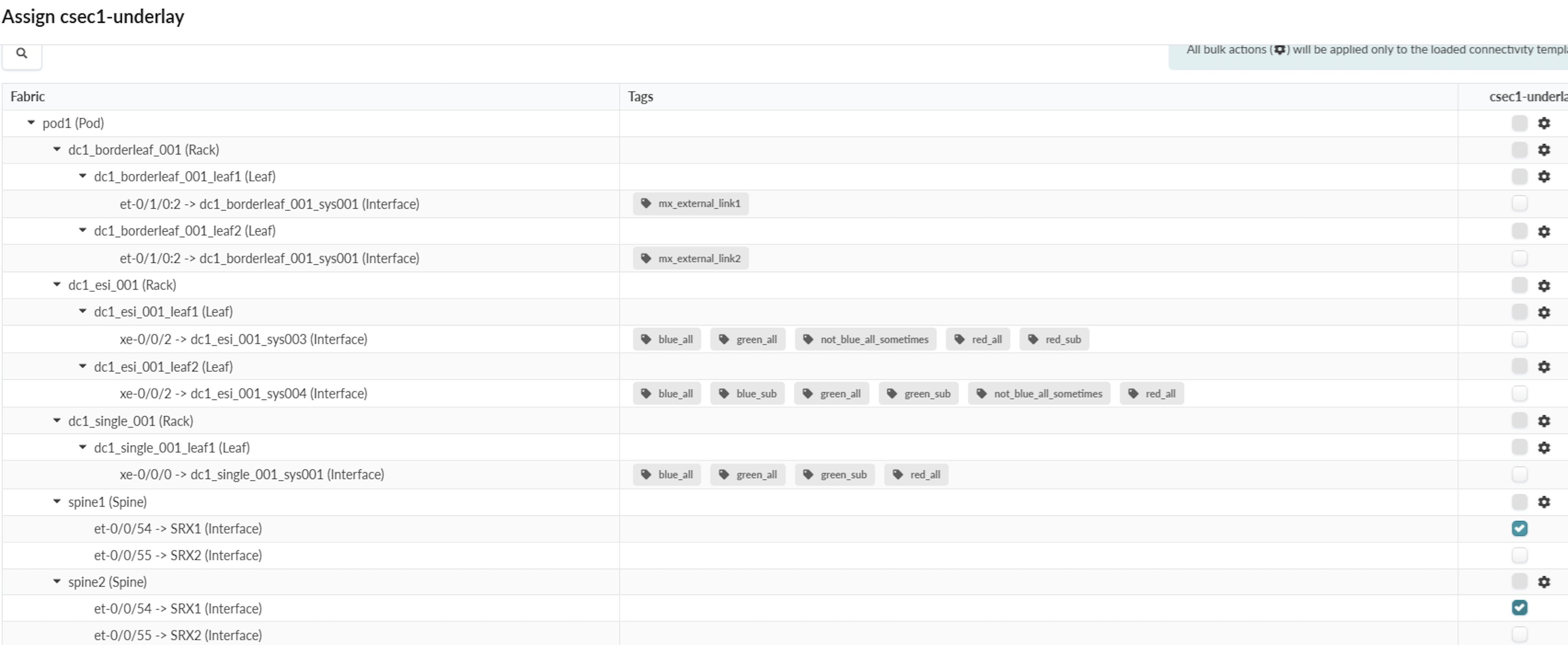
After creating the connectivity template, the template is then assigned to the Spine switches as shown in Figure 8.
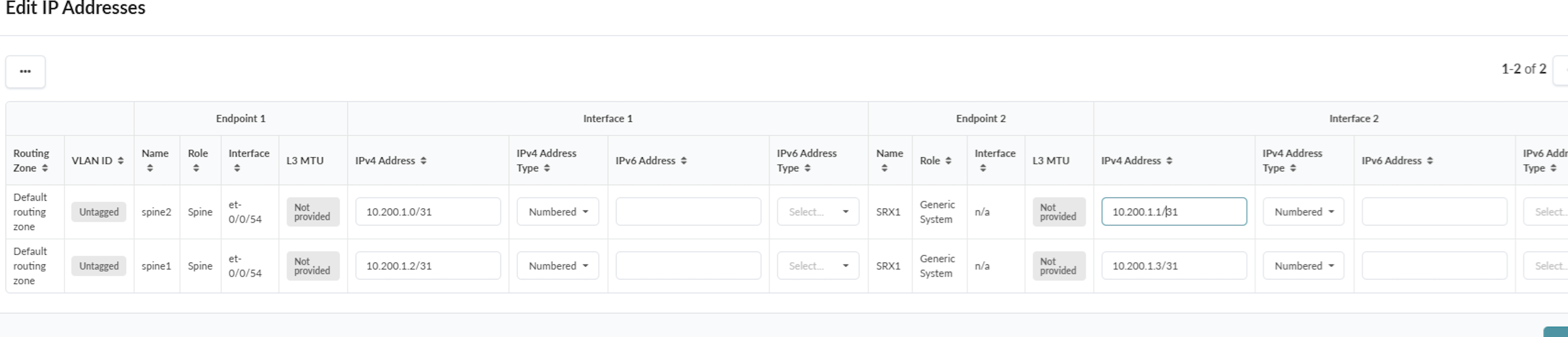
Assign Underlay IP Addresses to Spine and SRX Device Interfaces
Once the connectivity template is assigned, Apstra displays build errors (under Blueprints > {Blueprint Name} > Uncommitted) with suggestions when IP addresses need to be assigned to the interfaces. Navigate from the Blueprint > {Your Blueprint} > Staged > Virtual Network > Routing Zones and edit the Default Routing Zone as was assigned on the Connectivity template and scroll down to assign IP addresses as shown in Figure 9.
Configure Second SRX Device Connectivity to Spines
Once all the above configuration in Apstra is completed, repeat all the above steps for the second SRX device to create the underlay connectivity and the Remote EVPN gateway to Spine switches.
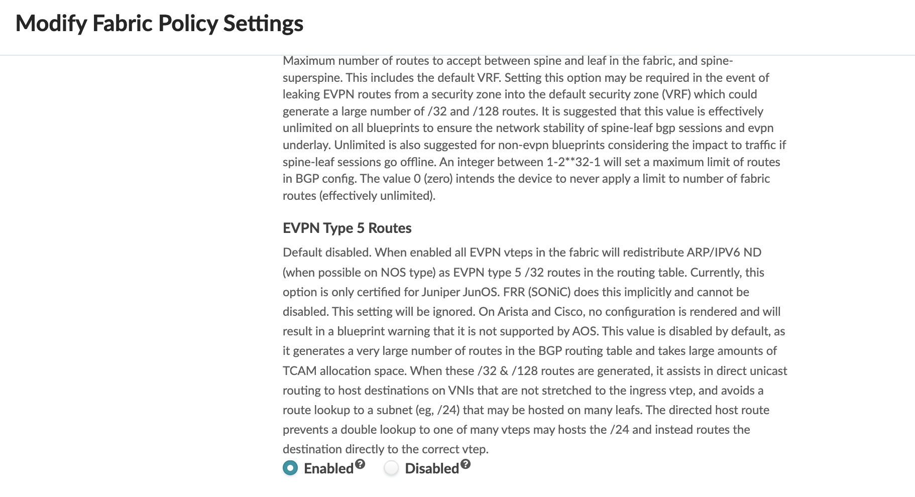
Enabling EVPN Type 5 Host Specific Routes
For host specific routes in Apstra Fabric setting, enable EVPN Type 5 routes as shown in Figure 10. This will increase routes in the BGP routing table depending on the number of hosts in the fabric. The default setting for EVPN Type 5 routes is disabled. Navigate to Blueprint > Staged > Fabric Settings. If this setting is disabled, then the routes shared will be the subnet prefix that is configured on the Virtual Network IP Subnet.
Committing Configuration on Spines
Once all the connectivity is configured in Apstra, commit the configuration to push the configuration on the Spine switches by navigating to Blueprints > { Blueprint name} > Uncommitted. For more information on committing the configuration, see Apstra guide. At this point any issues or errors should be cleared for the commit to be successful. However, the connectivity between Spine and SRX device will not be established until the SRX device is configured. This is discussed in next section of this JVDE.
After committing the configuration in Apstra, the below BGP configuration for the underlay and Overlay BGP peering with SRX is applied by Apstra on Spine switches. The configuration below shows the import and export of routes between Spine and the connected SRX device. In an EVPN‑VXLAN data center fabric, routing information is distributed to all leaf switches. This allows each leaf to learn every route and its associated next hop, enabling traffic forwarding toward other leaf switches or toward external destinations. Through the overlay BGP peering, EVPN Type 5 routes are shared by Spine with SRX firewall. As a result, the SRX learns all Type‑5 routes originating from the leaf switches.
By default, the behaviour of the EBGP multi-hop statement is to rewrite
the next hop. But to prevent this, Apstra also applies the
no-nexthop-change statement to prevent the Spine switches from
changing the next-hop for routes received from the leaf switches. Since leaf
switches learn the SRX firewall as the next-hop, traffic is steered towards the SRX
firewall where appropriate security policies are applied for relevant Inter-VRF
traffic as well as North-South traffic.
protocols {
   bgp {
        group l3rtr {
            type external;
            multihop {
                ttl 1;
            }
            family inet {
                unicast {
                    loops 2;
                }
            }
            family inet6 {
                unicast {
                    loops 2;
                }
            }
            multipath {
                multiple-as;
            }
            neighbor 10.200.1.1 {
                description facing_srx1;
                multihop {
                    ttl 2;
                }
                local-address 10.200.1.0;
                import ( RoutesFromExt-default-external_fwall );
                family inet {
                    unicast;
                }
                export ( RoutesToExt-default-external_fwall );
                peer-as 67001;
            }
            neighbor 10.200.1.5 {
                description facing_srx2;
                multihop {
                    ttl 2;
                }
                local-address 10.200.1.4;
                import ( RoutesFromExt-default-external_fwall );
                family inet {
                    unicast;
                }
                export ( RoutesToExt-default-external_fwall );
                peer-as 67002;
            }
            vpn-apply-export;
        }
        group evpn-gw {
            type external;
            multihop {
                ttl 30;
                no-nexthop-change;
            }
            multipath {
                multiple-as;
            }
            neighbor 192.168.250.1 {
                description facing_srx1-gw-evpn-gateway;
                multihop {
                    ttl 10;
                }
                local-address 192.168.255.5;
                hold-time 9;
                import ( EVPN_GW_IN_TYPE5 );
                family evpn {
                    signaling;
                }
                export ( EVPN_GW_OUT_TYPE5 );
                peer-as 67001;
            }
            neighbor 192.168.250.2 {
                description facing_srx2-gw-evpn-gateway;
                multihop {
                    ttl 10;
                }
                local-address 192.168.255.5;
                hold-time 9;
                import ( EVPN_GW_IN_TYPE5 );
                family evpn {
                    signaling;
                }
                export ( EVPN_GW_OUT_TYPE5 );
                peer-as 67002;
            }
            vpn-apply-export;
        }
        log-updown;
        graceful-restart {
            dont-help-shared-fate-bfd-down;
        }
       multipath;
   }
SRX Configuration
Multi-node high availability configuration
For Multinode high availability with two SRX4600 firewall devices, high availability configuration was set up as shown below on one of the nodes. The Inter-chassis link is configured for synchronization between the SRX firewall devices/nodes. The ICL is bound to the loopback interface, and an aggregated interface is used to ensure resiliency. The security zones are created for the ICL zone, and the policy are configured to allow communication between the nodes over the ICL link.
chassis {
    high-availability {
        local-id {
            2;
            local-ip 192.168.250.11;
        }
        peer-id 1 {
            peer-ip 192.168.250.10;
            interface ae0.0;
            routing-instance ICL;
            liveness-detection {
                minimum-interval 500;
                multiplier 3;
            }
        }
    }

 }
security {

    policies {

        from-zone ICL to-zone ICL {
            policy allow {
                match {
                    source-address default;
                    destination-address default;
                    application any;
                }
                then {
                    permit;
                }
            }
        }
    }

    zones {

        security-zone ICL {
            host-inbound-traffic {
                system-services {
                    ike;
                    high-availability;
                    ping;
                }
                protocols {
                    bfd;
                }
            }
            interfaces {
                ae0.0;
                lo0.1;
            }
        }
    }
}
interfaces {
    xe-1/1/0 {
        ether-options {
            802.3ad ae0;
        }
    }
    xe-1/1/1 {
        ether-options {
            802.3ad ae0;
        }
    }
    xe-1/1/2 {
        ether-options {
            802.3ad ae0;
        }
    }
    xe-1/1/3 {
        ether-options {
            802.3ad ae0;
        }
    }
    ae0 {
        unit 0 {
            family inet {
                address 10.222.222.2/30;
            }
        }
    }
    lo0 {
        unit 0 {
            family inet {
                address 192.168.250.2/32;
            }
        }
        unit 1 {
            family inet {
                address 192.168.250.11/32;
            }
        }
    }
}
routing-instances {
    ICL {
        instance-type virtual-router;
        routing-options {
            static {
                route 192.168.250.10/32 next-hop 10.222.222.1;
            }
        }
        interface ae0.0;
        interface lo0.1;
    }
}
BGP peering between SRX and spine
After configuring the spines to connect to SRX devices. Next configure the underlay and overlay peering on SRX devices:
root@mft-srx4600-01> show configuration protocols bgp
group underlay {
    type external;
    export loops;
    neighbor 10.200.1.0 {
        peer-as 64512;
    }
    neighbor 10.200.1.2 {
        peer-as 64513;
    }
}
group overlay {
    type external;
    multihop;
    advertise-peer-as;
    family inet {
        unicast;
    }
    family evpn {
        signaling;
    }
    export overlay-out;
    multipath {
        multiple-as;
    }
    as-override;
    neighbor 192.168.255.5 {
        local-address 192.168.250.1;
        peer-as 64512;
    }
    neighbor 192.168.255.6 {
        local-address 192.168.250.1;
        peer-as 64513;
    }
    vpn-apply-export;
}
Next, configure the policy options to export/import routes for the VRF and define community.
root@mft-srx4600-01> show configuration policy-options
policy-statement blue_EXPORT {
    term 1 {
        then {
            community add COMM_blue;
            accept;
        }
    }
}
policy-statement blue_IMPORT {
    term 1 {
        from community [ COMM_blue COMM_red COMM_green COMM_yellow ];
        then accept;
    }
}
policy-statement green_EXPORT {
    term 1 {
        then {
            community add COMM_green;
            accept;
        }
    }
}
policy-statement green_IMPORT {
    term 1 {
        from community [ COMM_blue COMM_red COMM_green COMM_yellow ];
        then accept;
    }
}
policy-statement loops {
    term 1 {
        from {
            protocol direct;
            interface lo0.0;
        }
        then accept;
    }
}
policy-statement overlay-out {
    term 1 {
        from {
            instance red;
            family evpn;
            route-filter 0.0.0.0/0 exact;
        }
        then accept;
    }
    term 2 {
        from {
            instance red;
            family evpn;
            route-filter 0::0/0 exact;
        }
        then accept;
    }
    term 10 {
        from {
            instance blue;
            family evpn;
            route-filter 0.0.0.0/0 exact;
        }
        then accept;
    }
    term 11 {
        from {
            instance blue;
            family evpn;
            route-filter 0::0/0 exact;
        }
        then accept;
    }
    term 20 {
        from {
            instance green;
            family evpn;
            route-filter 0.0.0.0/0 exact;
        }
        then accept;
    }
    term 21 {
        from {
            instance green;
            family evpn;
            route-filter 0::0/0 exact;
        }
        then accept;
    }
    term 700 {
        from {
            instance red;
            family evpn;
        }
        then reject;
    }
    term 800 {
        from {
            instance green;
            family evpn;
        }
        then reject;
    }
    term 900 {
        from {
            instance blue;
            family evpn;
        }
        then reject;
    }
}
policy-statement red_EXPORT {
    term 1 {
        then {
            community add COMM_red;
            accept;
        }
    }
}
policy-statement red_IMPORT {
    term 1 {
        from community [ COMM_red COMM_blue COMM_green COMM_yellow ];
        then accept;
    }
}
policy-statement yellow_EXPORT {
    term 1 {
        then {
            community add COMM_yellow;
            accept;
        }
    }
}
policy-statement yellow_IMPORT {
    term 1 {
        from community [ COMM_red COMM_blue COMM_green COMM_yellow ];
        then accept;
    }
}
community COMM_blue members target:20002:1;
community COMM_green members target:20004:1;
community COMM_red members target:20001:1;
community COMM_yellow members target:20005:1;
root@mft-srx4600-01>
Configure the routing instance with EVPN-VXLAN configuration and include the different route distinguishers. Then, configure the VRF or routing instance with import and export policies to allow inter-VRF communication.
root@mft-srx4600-01> show configuration routing-instances blue
instance-type vrf;
routing-options {
    rib blue.inet6.0 {
        static {
            route 0::0/0 {
                discard;
                preference 180;
            }
        }
    }
    static {
        route 0.0.0.0/0 {
            discard;
            preference 180;
        }
    }
    multipath;
}
protocols {
    evpn {
        interconnect {
            vrf-target target:20002:1;
            route-distinguisher 192.168.250.1:3;
        }
        ip-prefix-routes {
            advertise direct-nexthop;
            encapsulation vxlan;
            vni 20002;
        }
    }
}
route-distinguisher 192.168.250.1:11;
vrf-import blue_IMPORT;
vrf-export blue_EXPORT;
vrf-table-label;
root@mft-srx4600-01> show configuration routing-instances yellow
instance-type vrf;
routing-options {
    multipath;
}
protocols {
    evpn {
        interconnect {
            vrf-target target:20005:1;
            route-distinguisher 192.168.250.1:5;
        }
        ip-prefix-routes {
            advertise direct-nexthop;
            encapsulation vxlan;
            vni 20005;
        }
    }
}
route-distinguisher 192.168.250.1:13;
vrf-import yellow_IMPORT;
vrf-export yellow_EXPORT;
vrf-table-label;
root@mft-srx4600-01> show configuration routing-instances green
instance-type vrf;
routing-options {
    rib green.inet6.0 {
        static {
            route 0::0/0 {
                discard;
                preference 180;
            }
        }
    }
    static {
        route 0.0.0.0/0 {
            discard;
            preference 180;
        }
    }
    multipath;
}
protocols {
    evpn {
        interconnect {
            vrf-target target:20004:1;
            route-distinguisher 192.168.250.1:4;
        }
        ip-prefix-routes {
            advertise direct-nexthop;
            encapsulation vxlan;
            vni 20004;
        }
    }
}
route-distinguisher 192.168.250.1:12;
vrf-import green_IMPORT;
vrf-export green_EXPORT;
vrf-table-label;
root@mft-srx4600-01>
root@mft-srx4600-01>
root@mft-srx4600-01> show configuration routing-instances red
instance-type vrf;
routing-options {
    rib red.inet6.0 {
        static {
            route 0::0/0 {
                discard;
                preference 180;
            }
        }
    }
    static {
        route 0.0.0.0/0 {
            discard;
            preference 180;
        }
    }
    multipath;
}
protocols {
    evpn {
        interconnect {
            vrf-target target:20001:1;
            route-distinguisher 192.168.250.1:2;
        }
        ip-prefix-routes {
            advertise direct-nexthop;
            encapsulation vxlan;
            vni 20001;
        }
    }
}
route-distinguisher 192.168.250.1:10;
vrf-import red_IMPORT;
vrf-export red_EXPORT;
vrf-table-label;
A VRF group bundles multiple VRFs (routing instances) together so they can be governed by a single security policy.
root@mft-srx4600-01> show configuration security l3vpn
vrf-group VRF_GROUP1 {
    vrf [ blue green ];
}
root@mft-srx4600-01>
Define the security zone
To define a security policy, it is essential to understand the concept of security zones within your network. The concept of zones is a fundamental building block for security architecture on Juniper devices. It is used to segment the network based on trust levels and enforces granular control on the flow of traffic between the different network segments.
A security zone on a Juniper SRX firewall is a logical grouping of one or more interfaces that share the same security requirements. Instead of applying security policies to individual interfaces, you can apply them to zones. This simplifies management and configuration. All interfaces must belong to a zone. By default, interfaces are placed in a "null zone" where all traffic is dropped. Traffic is allowed only when the interface is configured in a zone as shown below.
root@mft-srx4600-01> show configuration security zones security-zone untrust
host-inbound-traffic {
    system-services {
        all;
    }
    protocols {
        all;
    }
}
interfaces {
    et-1/0/0.0;
    et-1/0/1.0;
    lo0.0;
}
Define the security policy
In the configuration below, we created an intra zone policy, where traffic enters the SRX device from zone “untrust” and exits through zone “untrust” on the SRX device.
root@mft-srx4600-01> show configuration security policies from-zone untrust to-zone untrust
policy VRF-BLOCK {
    match {
        source-address [ blue_hosts green_hosts green_sub_hosts blue_sub_hosts blue_v6_hosts green_v6_hosts blue_v6_sub_hosts green_v6_sub_hosts default default_v6 ];
        destination-address [ red_hosts red_sub_hosts red_v6_hosts red_sub_v6_hosts ];
        application any;
        source-l3vpn-vrf-group VRF_GROUP1;
    }
    then {
        reject;
    }
}
policy VRF-POl1 {
    match {
        source-address [ blue_hosts green_hosts green_sub_hosts blue_sub_hosts blue_v6_hosts green_v6_hosts blue_v6_sub_hosts green_v6_sub_hosts ];
        destination-address [ blue_hosts blue_sub_hosts green_hosts green_sub_hosts blue_v6_hosts green_v6_hosts blue_v6_sub_hosts green_v6_sub_hosts default default_v6 ];
        application any;
        source-l3vpn-vrf-group VRF_GROUP1;
    }
    then {
        permit;
    }
}
policy untr-untr-bfd {
    match {
        source-address [ SPINE1-LOOPBACK SPINE2-LOOPBACK LOOPBACK ];
        destination-address [ SPINE1-LOOPBACK SPINE2-LOOPBACK LOOPBACK ];
        application any;
    }
    then {
        permit;
    }
}
root@mft-srx4600-01>
To verify that the firewalls are functional and the changes are configured, log into the console or CLI of each of the firewalls. From the shell, enter the following Junos OS CLI command:
show bgp summary | no-more
The output of this command should be similar to the output below. It shows that BGP is established from each spine to SRX underlay and overlay.
root@mft-srx4600-01> show bgp summary
Threading mode: BGP I/O
Default eBGP mode: advertise - accept, receive - accept
Groups: 3 Peers: 4 Down peers: 0
Table          Tot Paths  Act Paths Suppressed    History Damp State    Pending
inet.0
                      12          7          0          0          0          0
bgp.evpn.0
                   11060       5530          0          0          0          0
Peer                     AS      InPkt     OutPkt    OutQ   Flaps Last Up/Dwn State|#Active/Received/Accepted/Damped...
10.200.1.0            64512        147        146       0       0     1:04:40 Establ
  inet.0: 6/6/6/0
10.200.1.2            64513        146        150       0       0     1:04:28 Establ
  inet.0: 1/6/6/0
192.168.255.5         64512       1839       1735       0       0     1:04:30 Establ
  bgp.evpn.0: 3537/5530/5530/0
  blue.evpn.0: 3537/5530/5530/0
  green.evpn.0: 3537/5530/5530/0
  red.evpn.0: 3537/5530/5530/0
  yellow.evpn.0: 3537/5530/5530/0
192.168.255.6         64513       1832       1807       0       0     1:04:26 Establ
  bgp.evpn.0: 1993/5530/5530/0
  blue.evpn.0: 1993/5530/5530/0
  green.evpn.0: 1993/5530/5530/0
  red.evpn.0: 1993/5530/5530/0
  yellow.evpn.0: 1993/5530/5530/0
root@mft-srx4600-01>
If the output of the show bgp summary | no-more command resembles the screenshot above, a bare-bones network fabric is now complete with SRX integration.
Verify EVPN under each routing instance.
root@mft-srx4600-01> show evpn l3-context extensive
L3 context: blue
  Type: Configured
  Advertisement mode: Direct nexthop, Router MAC: 9c:5a:80:3e:31:c4
  Encapsulation: VXLAN, VNI: 20002
  IPv4 source VTEP address: 192.168.250.1
  Flags: 0x61d <Configured Sys-MAC IRB-MAC New ROUTING ROUTING-NEW>
  Change flags: 0x33c0c <Adv-Mode Encap Dci-Config Dci-Rd-Change Dci-Import-Policy Dci-Export-Policy VXLAN-VNI-Update-RTT-OPQ>
  Composite nexthop support: Disabled
  Route Distinguisher: 192.168.250.1:11
  Reference count: 3343
  EVPN Multicast Routing mode: CRB
L3 context: green
  Type: Configured
  Advertisement mode: Direct nexthop, Router MAC: 9c:5a:80:3e:31:c4
  Encapsulation: VXLAN, VNI: 20004
  IPv4 source VTEP address: 192.168.250.1
  Flags: 0x61d <Configured Sys-MAC IRB-MAC New ROUTING ROUTING-NEW>
  Change flags: 0x33c0c <Adv-Mode Encap Dci-Config Dci-Rd-Change Dci-Import-Policy Dci-Export-Policy VXLAN-VNI-Update-RTT-OPQ>
  Composite nexthop support: Disabled
  Route Distinguisher: 192.168.250.1:12
  Reference count: 3343
  EVPN Multicast Routing mode: CRB
L3 context: red
  Type: Configured
  Advertisement mode: Direct nexthop, Router MAC: 9c:5a:80:3e:31:c4
  Encapsulation: VXLAN, VNI: 20001
  IPv4 source VTEP address: 192.168.250.1
  Flags: 0x61d <Configured Sys-MAC IRB-MAC New ROUTING ROUTING-NEW>
  Change flags: 0x33c0c <Adv-Mode Encap Dci-Config Dci-Rd-Change Dci-Import-Policy Dci-Export-Policy VXLAN-VNI-Update-RTT-OPQ>
  Composite nexthop support: Disabled
  Route Distinguisher: 192.168.250.1:10
  Reference count: 3343
  EVPN Multicast Routing mode: CRB
L3 context: yellow
  Type: Configured
  Advertisement mode: Direct nexthop, Router MAC: 9c:5a:80:3e:31:c4
  Encapsulation: VXLAN, VNI: 20005
  IPv4 source VTEP address: 192.168.250.1
  Flags: 0x61d <Configured Sys-MAC IRB-MAC New ROUTING ROUTING-NEW>
  Change flags: 0x33c0c <Adv-Mode Encap Dci-Config Dci-Rd-Change Dci-Import-Policy Dci-Export-Policy VXLAN-VNI-Update-RTT-OPQ>
  Composite nexthop support: Disabled
  Route Distinguisher: 192.168.250.1:13
  Reference count: 3343
  EVPN Multicast Routing mode: CRB
root@mft-srx4600-01>
Verify the route leaking is in effect properly across the routing-instance.
root@mft-srx4600-01> show route forwarding-table destination 10.1.0.101/32 table blue
Routing table: blue.inet
Internet:
Destination        Type RtRef Next hop           Type Index    NhRef Netif
10.1.0.0/24        user     0                    comp      885   136
root@mft-srx4600-01> show route forwarding-table destination 10.1.0.101/32 table green
Routing table: green.inet
Internet:
Destination        Type RtRef Next hop           Type Index    NhRef Netif
10.1.0.0/24        user     0                    comp      886   136
root@mft-srx4600-01> show route forwarding-table destination 10.1.0.101/32 table red
Routing table: red.inet
Internet:
Destination        Type RtRef Next hop           Type Index    NhRef Netif
10.1.0.0/24        user     0                    comp      884   136
root@mft-srx4600-01> show route forwarding-table destination 10.1.0.101/32 table yellow
Routing table: yellow.inet
Internet:
Destination        Type RtRef Next hop           Type Index    NhRef Netif
10.1.0.0/24        user     0                    comp      887   136
root@mft-srx4600-01>