
Solution Architecture
The telco cloud architecture consists of three main components, EVPN VXLAN data center Fabric, Baremetal/Virtual Machine/Kubernetes cluster as private telco cloud compute and an offramp gateway which makes it easier to individually manage and operate all these components and scale easily without impacting each component.
EVPN VXLAN Data Center Fabric
For most Telco cloud use cases, 3-stage Clos Bridged Overlay architecture should suffice. In this architecture, lean spine switches are connected to the server leaf switches and border leaf switches. The Server leaf switches host the compute components, and the Border Leaf switches are then connected to the offramp gateway, see Figure 1: Hybrid Telco Cloud Solution Architecture.
In this validated design, the fabric is designed with an IPv6 underlay and adopts both Bridged Overlay and Border Leaf Routing models.
Bridged Overlay (BO) for SR-IOV Services
SR-IOV services use a Bridged Overlay approach, with Q-in-Q traffic transported across the EVPN-VXLAN fabric and terminated on the Off-Ramp Gateway for Layer 3 processing. Traffic is forwarded based on the outer Service VLAN (S-VLAN), which is mapped to a VNI within the EVPN-VXLAN fabric. The inner Customer VLAN (C-VLAN) is preserved across the fabric and is used to identify the tenant network. Layer 3 processing and inter-network routing for SR-IOV traffic are performed on the Off-Ramp Gateway, where the Q-in-Q services are terminated.
Border Leaf Routing for JCNR Services
JCNR services use Anycast gateway (IRB) hosted on the Border Leaf switches to provide Layer 3 east-west connectivity between JCNR instances within the same tenant. Traffic requiring inter-subnet connectivity is forwarded through the Border Leaf and, where required, towards the Off-Ramp Gateway for tenant policy enforcement, route leaking, and external connectivity.
The fabric provides high availability through ESI-LAG connectivity between the server-facing leaf switches and compute nodes, ensuring resilient access to compute, storage, and network resources. The fabric provides tenant isolation using a dedicated EVPN instance (MAC-VRF) per tenant. For SRIOV-connected workloads, the per-tenant MAC-VRF isolation additionally enables the transport of multiple overlapping CVLAN groups in Layer 2 mode across the fabric to the Off-Ramp Gateway. This allows for separation of tenant traffic generated from compute, storage and network services including provision of high-performance connectivity directly from the workloads hosted on Virtual Machines (VMs), bare metal, and Kubernetes based workloads to the wider network.
As discussed earlier, HPE Juniper data center switches QFX5130-32CD are used as server leaf and border leaf switches. QFX5230-64CD is used as high port density Spine switches that allow for future growth. The fabric can be conveniently provisioned using Apstra intent based platform using the SP Data Center Reference architecture that’s available from Apstra 6.2. This allows for most private Telco scenarios to be managed and monitored using Apstra.
Compute Networking
The EVPN VXLAN fabric provides network services to allow for interconnecting physical and virtualized server components for a tenant in highly scalable manner. Depending on the Telco Cloud providers use case there are two main overlay networking within the compute server space - Host Based Overlay and Network-based overlays.
Host-Based Routing (HBR) Using Juniper Cloud Native Router
Host based routing is responsible for constructing overlay networks within the context of single tenant. The overlays stretch from host to host (East-West) or from host to DC Offramp Gateway.
Juniper Cloud-Native Router (JCNR) is a containerized router that combines Juniper’s proven routing technology with the Junos OS containerized routing protocol daemon (cRPD) as the controller and a high-performance Data Plane Development Kit (DPDK) or extended Berkley Packet Filter (eBPF) eXpress Data Path (XDP) datapath based vRouter forwarding plane. It is implemented in Kubernetes and interacts seamlessly with a Kubernetes container network interface (CNI) framework. The third component is the Cloud-Native Router container network interface (CNI) that interacts with Kubernetes as a secondary CNI to create pod interfaces, assign addresses and generate the router configuration. For more information on JCNR, see JCNR guide.
JCNR can support EVPN VXLAN and MPLS-over-UDP as overlay. For this Telco Cloud validated design, MPLS-over-UDP is selected as JCNR overlays to prevent VNI collisions between the Fabric and the JCNR overlays. With this approach, the host is not required to function as a leaf switch. From an operations perspective, Apstra Data Center Director can control the management of the fabric VXLAN overlays seamlessly.
Network-based VXLAN Overlays
SR-IOV is an extension to the PCI Express (PCIe) specification that provides virtualization of physical cards such as network adapters to access resources enabling near-real time traffic. This allows Virtual Machines (VMs) to bypass the software switch layer of the Hyper-V virtualization stack and directly access physical network hardware. For this reason, SR-IOV workloads use network-based overlays to map the bare metal traffic into the EVPN VXLAN fabric. A customer VLAN (C-VLAN) is configured on the bare metals hosting the SR-IOV workloads. A service-VLAN (S-VLAN) is then used to provide Q-in-Q tagging to bundle the C-VLAN traffic towards the server leaf switch that is hosting the bare metal. The Server leaf then encapsulates the Q-in-Q traffic into EVPN VXLAN overlays that route the traffic towards Border leaf and then finally towards to the Offramp Gateway where all the routing decisions are made.
Offramp Gateway
The Offramp gateway serves as Gateway between the Data Center Fabric and the external network, including Public Cloud VPC gateways running Juniper Cloud Native Router (JCNR). The offramp gateway performs following functions:
- The Border leaf switches from the fabric connect to the offramp gateway routers to terminate the overlays from the computes such MPLS-over-UDP and the Q-in-Q tunnels as discussed above in the Compute Networking section.
- The Offramp gateway performs inter-VRF routing between tenants as well as between SR-IOV and JCNR-based workloads.
- In hybrid telco environments, the Public Cloud VPC gateways advertise NLRI (Network Layer Reachability Information) via BGP to seamlessly connect private and public telco cloud infrastructure.
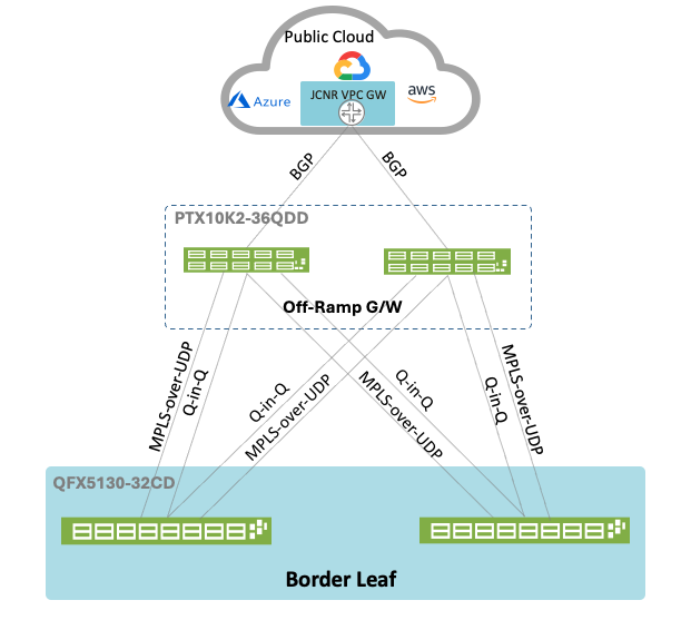
In a production network, deploying two PTX10002-36QDD routers as Offramp Gateways is recommended for high availability. Each border leaf connects two physical interfaces towards the offramp gateway routers, one for L2 traffic i.e. Q-in-Q and the other for MPLS-over-UDP (L3) traffic as shown in Figure 2: Offramp Gateway Connectivity.
For the purpose of this validated design, only one PTX10002-36QDD router is deployed as Offramp Gateway. The design assumes that the Border leaf switches are not directly connected and there may be other Layer 3 connectivity in between the border leaf switch and Offramp gateway. Due to the current limitation whereby Q-in-Q services cannot be terminated directly on the IRB interfaces on the border leaf switches, a dummy interface (physical loopback construct) is implemented on the Off-Ramp Gateway. This interface provides a routing transition point between the Layer 3 VPN services hosted in tenant VRFs and the Layer 2 EVPN-VXLAN domain used for SR-IOV traffic transport.
Note: The term ‘Physical loopback’ is used to define the implementation in this validated design. It should not be mistaken for the loopback interface. The implementation is a workaround for the current Q-in-Q service termination limitation and should not be considered a fundamental architectural requirement. Future enhancements that support direct Q-in-Q termination on IRB interfaces may eliminate the need for this construct.
Figure 2: Offramp Gateway Connectivity
Virtual Route Reflector (vRR)
JCNR instances are deployed on a per-tenant basis and must learn VPN and service routes from the network. Establishing direct BGP peering between every JCNR instance and all relevant network devices would create a complex and difficult-to-manage BGP topology as the environment scales. To simplify the control plane, a Virtual Route Reflector (vRR) is deployed on the Kubernetes controller node(s).
Centralized Route Reflector
The vRR performs the role of centralized route reflector for the JCNR environment and is responsible for distributing BGP routing information between JCNR and the offramp gateway. Each JCNR instance establishes an internal BGP (iBGP) session with the vRR using its loopback address as the BGP endpoint over the data center IP fabric. The vRR reflects VPN routing information to all participating JCNR instances, eliminating the need for a full-mesh BGP topology.
The off-ramp gateway establishes internal BGP (iBGP) peering with the vRR using the data center fabric infrastructure network to exchange tenant routes, Route targets and JCNR service reachability. Tenant routes originating from SR-IOV and JCNR VRFs are advertised as VPNv6 routes and selectively tagged with Route Targets through export policies. The vRR reflects these routes to the appropriate JCNR instances, enabling controlled route sharing, MPLS-over-UDP tunnel reachability, and communication between JCNR and SR-IOV service domains.
Centralized Inter-VRF Reachability for JCNR-to-vRR Control Plane Sessions
The JCNR loopback addresses reside within tenant-specific VRFs (for example, VRF_4001), whereas the vRR is reachable through a dedicated control-plane VRF (VRF_CRPD_4010). As these routing domains are isolated, direct IP reachability between the JCNR and vRR endpoints cannot be provided by the EVPN-VXLAN fabric alone.
To enable BGP session establishment, the off-ramp Gateway performs the required inter-VRF route leaking between the tenant VRFs and the vRR-facing VRF. Consequently, while the iBGP relationship exists logically between the JCNR instances and the vRR, the reachability required to establish and maintain those sessions is provided through the Off-Ramp Gateway. The objective is not to minimize hop count but to centralize all inter-VRF connectivity, policy enforcement, and route leaking functions on the Off-Ramp Gateway. This approach preserves tenant isolation and avoids distributing route-leaking logic across multiple leaf switches or Kubernetes nodes.
Border Leaf Switch Anycast IRB Role
The Border Leaf Switch Anycast IRBs provide Layer 3 gateway services within individual routing domains and enable IP reachability across the EVPN-VXLAN fabric. However, they do not perform inter-VRF forwarding between tenant VRFs and the vRR control-plane VRF.
For example, a JCNR loopback may reside in a tenant VRF such as VRF_4001, while the vRR is reachable through a dedicated control-plane VRF such as VRF_CRPD_4010. The Border Leaf Anycast IRB can provide forwarding within each VRF but cannot directly route traffic between them.
When a JCNR instance initiates a BGP session towards the vRR, traffic remains within the tenant VRF while traversing the EVPN-VXLAN fabric until it reaches the Off-Ramp Gateway, where inter-VRF route leaking is applied. The off-ramp gateway then performs the required inter-VRF route lookup and inter-VRF route leaking from the tenant VRF into the control-plane VRF. Once the route has been resolved in the control-plane VRF, the packet is forwarded toward the vRR. The reverse route is leaked in the opposite direction, ensuring bidirectional reachability for the BGP/TCP session.
Consequently, even when the JCNR instance and vRR are physically connected to the same leaf pair, physical proximity does not eliminate the VRF boundary. Traffic must still traverse the Off-Ramp Gateway because the offramp gateway serves as the centralized inter-VRF routing and policy enforcement point for the architecture.
The Border Leaf Switch Anycast IRBs and the Off-ramp gateway therefore serve complementary functions as listed in Table 1: Border Leaf Anycast Gateway (IRBs) and Off-Ramp Gateway Function.
Table 1: Border Leaf Anycast Gateway (IRBs) and Off-Ramp Gateway Function
| Border Leaf Anycast IRBs | Off-Ramp Gateway |
|---|---|
| Provide Layer 3 gateway functionality within a VRF. | Acts as the routing boundary between tenant and control-plane VRFs. |
| Enable reachability across the EVPN-VXLAN fabric. | Supports inter-network, inter-tenant, and external connectivity. |
| Do not perform cross-VRF route leaking. |
Performs inter-VRF route leaking. Provides centralized routing policy enforcement. |
Fabric Role
The EVPN-VXLAN fabric serves as the underlying transport infrastructure for both control-plane and data-plane communications. The fabric provides IP reachability between the JCNR instances, Virtual Route Reflectors (vRRs), and the Off-Ramp Gateway, while maintaining tenant isolation through EVPN-VXLAN forwarding domains.
For control-plane communications, the fabric transports iBGP traffic between the JCNR instances, the vRR, and the Off-Ramp Gateway. For data plane communications, the fabric transports MPLS-over-UDP traffic between the JCNR data plane endpoints and the Off-Ramp Gateway.
The fabric does not perform route reflection, VPN route distribution, or inter-VRF route leaking. These functions are provided by the vRR and the Off-Ramp Gateway, respectively.
The vRR reduces operational complexity of BGP peering and improves scalability as additional JCNR instances can be added without increasing BGP peering. More details about configuration, see Apstra: Provision Overlay Network and BGP Sessions to Advertise Routes sections.