
Solution Walkthrough
The validated design focusses mainly on the network aspect such as data center fabric and the JCNR, while briefly covering Kubernetes and SR-IOV configuration from network configuration perspective. The configuration of the applications and tools that generate compute traffic in the network overlay are out of scope as this depends mainly upon each customer use case.
Data Center Fabric Using HPE Juniper Configuration
The Data center fabric serving the compute infrastructure is provisioned using HPE Apstra Data Center Director (Apstra). The procedure to create logical devices, Interface maps and adding devices to Apstra for management is similar to configuration steps discussed in Juniper Validated 3-Stage EVPN/VXLAN Fabric with Juniper Apstra—Juniper Validated Design (JVD) and this validated design covers the variations required to Telco Service Provider Data Center Reference design Blueprint.
Apstra: Provisioning IPv6 Fabric
Once all the devices are added into Apstra, the devices are acknowledged. For each device type Apstra requires a Logical Device and associated Interface Map created that should be associated with Device Profile. The devices recommended for this validated design are listed in Table 2: Telco Cloud Service Provider Devices and Positioning. The logical devices and associated Interface Maps are shown here that represent the device uplinks towards Spine switches and downlinks towards Servers. There needs to be a sufficient count of links created as a logical device which is then used to associate device Profile to Interface Maps where the actual interface is selected based on physical connectivity setup.
QFX5130-48C as Server Leaf Switches
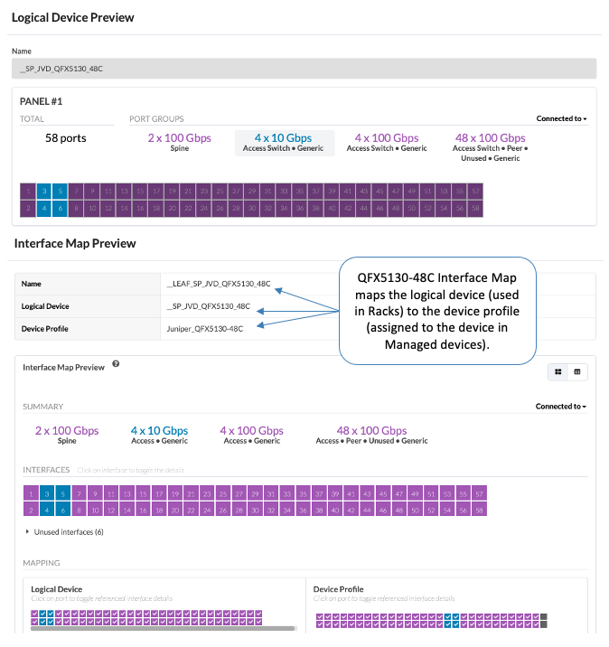
The server leaf switches used in this architecture are QFX5130-48C. The logical device and Interface Map created based on the switch connectivity towards Spine and servers is shown in Figure 3: QFX5130-48C Logical Device and Interface Map.
Figure 3: QFX5130-48C Logical Device and Interface Map
QFX5130-32CD as Border Leaf Switches
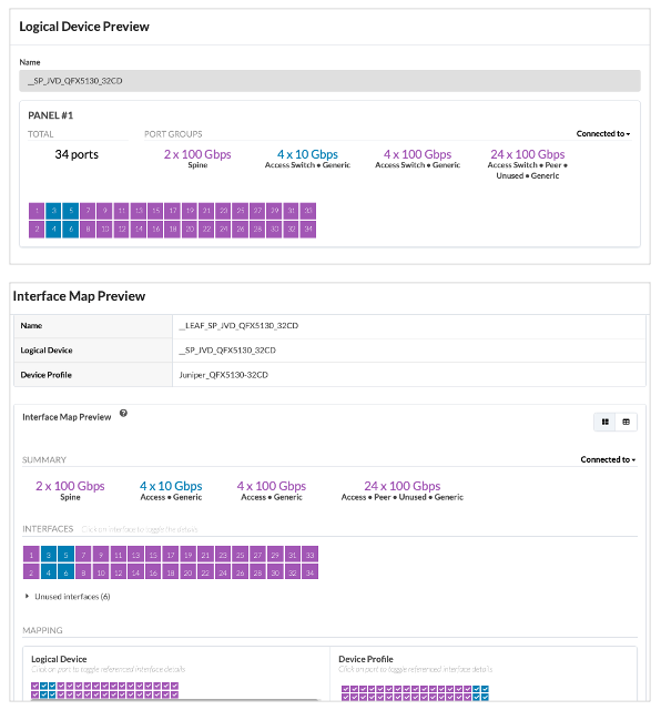
The border leaf switches used in this architecture are QFX5130-32CD. The logical device and Interface Map is created based on the physical switch connectivity to Spine switches as uplinks and towards the Offramp Gateway router.
Figure 4: Logical Device and Interface Map of Leaf Switch QFX5130-32CD
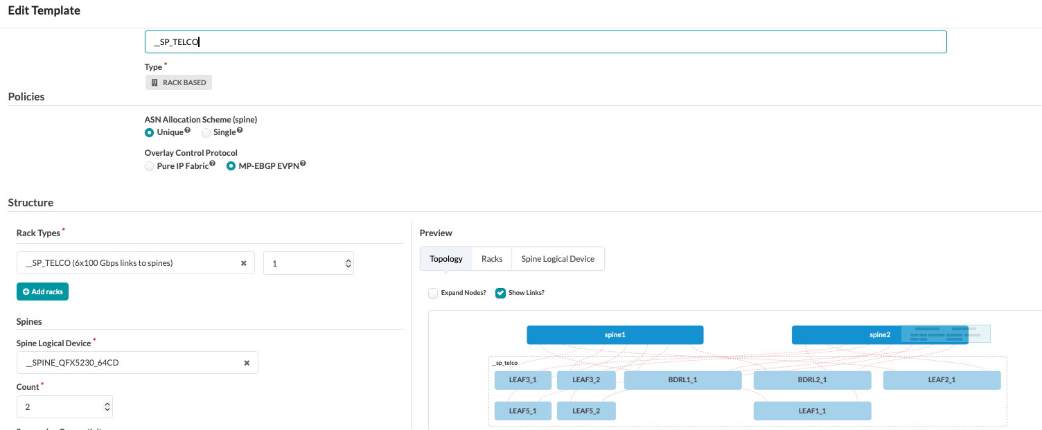
To create Apstra Blueprint, blueprint template is created first as shown in Figure 5: Blueprint Template. The rack is added and associated with the Spine’s logical device. In this validated design only 2 Spine switches are used. However, this number could be higher for large scale setup and can be increased using Apstra Blueprint.
Figure 5: Blueprint Template
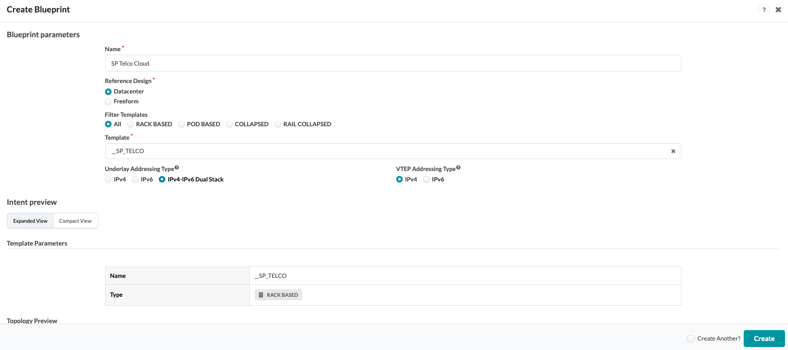
After creating the template, a blueprint is created from the template. The Telco fabric design uses IPv6 underlay and overlay.
Figure 6: Blueprint
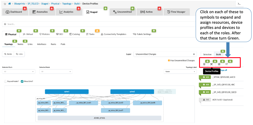
After creating Blueprint, resources such as ASN pools, IPv6 Loopback Address Pools and IPv6 Link Address Pools under Blueprint > Staged. The interface maps can be selected under Blueprint > Staged > Device Profiles, to ensure the correct Interface Map is selected ensure the device profile, The devices are also assigned under Systems, if the rack contains the appropriate logical device and the appropriate Interface Maps are available under Blueprint > Staged > Catalog. If Interface map is not visible under Catalog then review it to ensure the Interface Map is correctly associated to the device profile and the logical device. The interface map should also be created with the appropriate transformation that matches the device Interfaces so that the cable connectivity is correctly identified.
Figure 7: Assign Resources, System ID and Device Profiles in Blueprint
After the devices are assigned, ensure that the cabling is correctly picked up by Apstra. Navigate to Blueprints > Staged > Physical and click on Links. Alternatively, click on Fetch discovered LLDP data to discover the links. LLDP configuration is applied when the devices are added to Apstra.
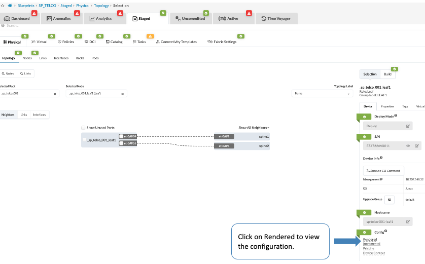
By now all the basic underlay IPv6 fabric configuration is created by Apstra which is not pushed to the switches till Commit is performed. To review the configuration, navigate to Blueprint > Staged > Physical and either Select devices from Topology or Click on Nodes and then click on device, which presents a screen with option to view the rendered configuration as shown in Figure 8: View Rendered Configuration.
Figure 8: View Rendered Configuration
Underlay Configuration Applied by Apstra
Once all the changes are committed, Apstra version 6.2 applies the underlay configuration across the spine and leaf switches like the Enterprise Data Center design. Although dual stack is selected while creating blueprint, this validated design proposes IPv6 underlay and overlay solution.
EVPN/VXLAN Fabric with IPv6 Underlay
EVPN VXLAN with an IPv6 underlay uses IPv6 for the underlying network infrastructure to connect Virtual Tunnel Endpoints (VTEPs), allowing for a larger IP address space and more efficient packet processing. This setup enables modern routing protocols like BGP unnumbered peering in the underlay and supports overlay hosts that can be either IPv4 or IPv6. BGP unnumbered peering streamlines the configuration of an IPv6 underlay in an EVPN-VXLAN data center fabric by automatically discovering IPv6 neighbors, eliminating the need for manual setup.
Note: Apstra automatically provides similar functionality to BGP unnumbered peering, eliminating the need for manual configuration within this Validated Design.
In case BGP unnumbered is required, a configlet could be used in Apstra, if Apstra is used for managing the network. For more information on BGP unnumbered peering, also known as BGP auto-discovery or BGP auto-peering see AI Multitenancy validated design.
A snippet of BGP unnumbered config is attached in Appendix A of this validated design document, in case BGP unnumbered is required and Apstra is not used for managing the network.
IPv6 Underlay Fabric with Apstra
There are different options to implement the underlay in an EVPN/VXLAN fabric, depending on design goals, operational preferences, and hardware capabilities.
- IPv4 addresses (/31 subnet masks) numbered interfaces
- IPv6 addresses (/127 subnet masks) numbered interfaces
- IPv6 link-local addresses (unnumbered interfaces), with BGP neighbor auto-discovery based on IPv6 neighbor discovery (RFC 4861) and IPv4 route advertisement via IPv6 next-hops (RFC 5549) for IPv4 overlays.
Starting with Apstra 6.1, IPv6 underlay is supported on all applicable supporting Devices (see the Apstra guide for more information).
Apstra statically assigns IPv6 addresses (/127 subnet masks) from IPv6 Pool (assigned to the blueprint) for fabric addressing which makes it easier to manage and avoid manually performing IP administration functions. This reduces operational complexity, especially in large-scale fabrics where scalability and automation are key. By using Apstra the need to assign and manage global IP addresses on leaf-to-spine links, eliminates a major source of administrative overhead.
In Apstra the resource group concept is used to create IP Address Pools. Each link is automatically assigned unique addresses once the IP address resource pool is assigned, streamlining both deployment and ongoing maintenance. This is a significant advantage in environments with thousands of interfaces. All leaf and spine nodes are also configured with IPv6 addresses on the loopback interface (lo0.0).
The underlay EBGP sessions are set up between the leaf and spine nodes, by explicitly configuring each neighbor, using the /127 IPv6 addresses assigned between them.Note: BGP unnumbered/auto-discovery is not configured as Apstra performs similar features without the need for manual assignment of IP address.
The EBGP configuration for this model includes each neighbor’s IPv6 address and Autonomous System (AS) number, the local Autonomous System (AS) number, and the export policy that allows the advertisement of routes to reach all the leaf and spine nodes in the fabric. These routes are standard IPv6 unicast advertising the IPv6 addresses assigned to the loopback interface (lo0.0).
Following is an example of the Apstra config snippet of the underlay EBGP configuration applied by Apstra:
protocols {
    bgp {
    group l3clos-l {
        type external;
        multipath {
            multiple-as;
        }
        bfd-liveness-detection {
            minimum-interval 1000;
            multiplier 3;
        }
        neighbor 2001:2001:2001:2001:: {
            description facing_spine1;
            local-address 2001:2001:2001:2001::1;
            family inet {
                unicast {
                    extended-nexthop;
                }
            }
            family inet6 {
                unicast;
            }
            export ( LEAF_TO_SPINE_FABRIC_OUT && BGP-AOS-Policy );
            peer-as 100;
        }
        neighbor 2001:2001:2001:2001::10 {
            description facing_spine2;
            local-address 2001:2001:2001:2001::11;
            family inet {
                unicast {
                    extended-nexthop;
                }
            }
            family inet6 {
                unicast;
            }
            export ( LEAF_TO_SPINE_FABRIC_OUT && BGP-AOS-Policy );
            peer-as 101;
        }
        vpn-apply-export;
    }
}
To verify that underlay BGP is established between the spine and leaf switches, execute the show bgp summary command on the spine switch’s CLI.
regress@spine2> show bgp summary

Warning: License key missing; requires 'BGP' license

Threading mode: BGP I/O
Default eBGP mode: advertise - accept, receive - accept
Groups: 2 Peers: 16 Down peers: 0
Table          Tot Paths  Act Paths Suppressed    History Damp State    Pending
inet.0
                      16          8          0          0          0          0
inet6.0
                      24         16          0          0          0          0
bgp.evpn.0
                     101        101          0          0          0          0
Peer                     AS      InPkt     OutPkt    OutQ   Flaps Last Up/Dwn State|#Active/Received/Accepted/Damped...
2001:2001:2001:2001::11         102        171        197       0       1     1:15:17 Establ
  inet.0: 1/2/2/0
  inet6.0: 2/3/3/0
2001:2001:2001:2001::13         103        244        274       0       0     1:47:59 Establ
  inet.0: 1/2/2/0
  inet6.0: 2/3/3/0
2001:2001:2001:2001::15         104        245        274       0       0     1:47:53 Establ
  inet.0: 1/2/2/0
  inet6.0: 1/2/2/0
2001:2001:2001:2001::17         105        244        274       0       0     1:48:09 Establ
  inet.0: 1/2/2/0
  inet6.0: 2/3/3/0
2001:2001:2001:2001::19         106        244        275       0       0     1:48:17 Establ
  inet.0: 1/2/2/0
  inet6.0: 2/3/3/0
2001:2001:2001:2001::1b         107        231        260       0       0     1:42:35 Establ
  inet.0: 1/2/2/0
  inet6.0: 2/3/3/0
2001:2001:2001:2001::1d         108        149        152       0       1     1:02:39 Establ
  inet.0: 1/2/2/0
  inet6.0: 3/4/4/0
2001:2001:2001:2001::1f         109        199        218       0       0     1:26:19 Establ
  inet.0: 1/2/2/0
  inet6.0: 2/3/3/0
Router-IDs for EBGP Sessions
Router IDs are used to uniquely identify each switch or router in the network. Because the underlay is IPv6 and uses the IPv6 address family to establish BGP connections, it is still essential to assign a 32‑bit router ID to ensure BGP functions correctly. The router ID is represented in the format of a unique IPv4 address. Following is the CLI configuration statement:
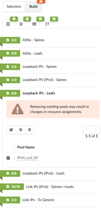
set routing-options router-id <loopback-ipv4-address>Apstra assigns the loopback IP from the Resources selected under Blueprint > Stage.
Figure 9: Assign IP Pool Under Resources After Creating Blueprint
Apstra: Provision Overlay Network
After the fabric is provisioned, next step is to configure the overlay network. To provision overlay network in Apstra, create Routing zone, Switching zone and Virtual Network. For more information on provisioning overlay network, see Apstra user guide.
For the purposes of the Service Provider Telco solution following are the key Virtual Network setup needed to allow JCNR and SR-IOV traffic flow from the compute to the destination host. The following examples provided to show context and understanding of the configuration required for this solution.
- JCNR per tenant: For JCNR traffic, per tenant routing zone (VRF), switching zone (EVPN Instance) are created and associated with the Virtual Network in Apstra.
- vRR: Without a route reflector, every JCNR would need to establish BGP sessions with multiple peers, creating a complex mesh. By using vRR which is setup on the tenant Kubernetes controller, JCNR can learn routes to reach destination host. An IBGP session is established between offramp gateway and the vRR instance which is covered later in this document and a IBGP session is established between JCNR and thee vRR instance. In Apstra, a routing zone, switching zone and virtual network is created to allow the control plane traffic between compute and the offramp gateway.
- SR-IOV per tenant per VN: For SR-IOV traffic, Q-in-Q encapsulation is required which can now be configured using Apstra version 6.2.
Routing Zone
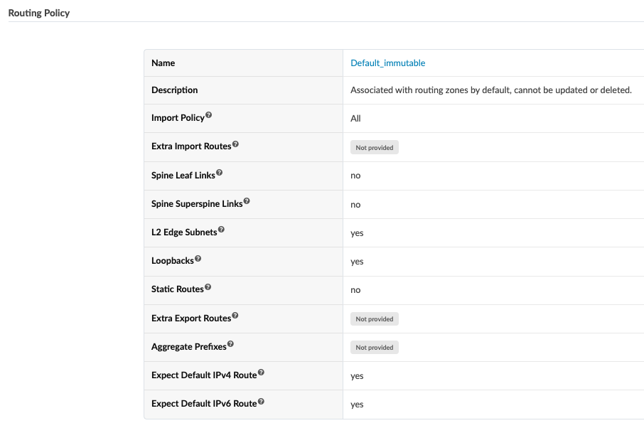
To create L3 routing zone (VRF) the Apstra routing zone is used to create all the L3 VRFs. A routing policy is created separately if variations are required in the policy, however in this validated design the default routing policy is applied in Apstra and assigned to the VRF instance.
Figure 10: Default Routing Policy Created by Apstra
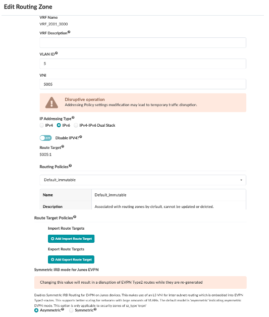
After creating routing policy, routing zone is created under Blueprints → Virtual in Apstra. A separate L3 VNI is assigned as shown in the following screenshot. This can be assigned after creating the routing zone and a resource pool can be used. The default routing policy is assigned. Lastly, the IRB type is selected. Asymmetric IRB is the default and is applied by both Junos OS and Apstra. However, the selected IRB type has no impact on this design because it uses a Bridged Overlay. The leaf switches operate at Layer 2 only, except for the border leaf switches, and all inter-vlan, inter-subnet routing decisions are handled by the off-ramp gateway. To understand more about Symmetric IRB, see Symmetric Integrated Routing and Bridging with EVPN Type 2 Routes in EVPN-VXLAN Fabrics. Also, the 3-stage IPv6 validated design has section that explains the difference between Asymmetric and Symmetric IRB.
Table 6: Routing Zone Example
| Parameters | JCNR Routing Zone Per Tenant | JCNR vRR | SR-IOV for All Virtual Networks Per Tenant |
|---|---|---|---|
| VRF Name | VRF_ALL_4001 | VRF_CRPD_4010 | VRF_2001_3000 |
| VRF Description | |||
| Type | EVPN | EVPN | EVPN |
| Tags | |||
| VLAN ID | 4 | 2 | 5 |
| VNI | 5004 | 5002 | 5005 |
| Route Target | 5004:1 | 5002:1 | 5005:1 |
| Junos EVPN IRB Mode | Symmetric | Symmetric | Asymmetric |
| DHCP Servers | DHCP Relay not configured | DHCP Relay not configured | DHCP Relay not configured |
For each of the routing zones IPv6 addressing is selected, but the IPv4 address is not disabled.
Figure 11: IP Addressing Type for Routing Zone
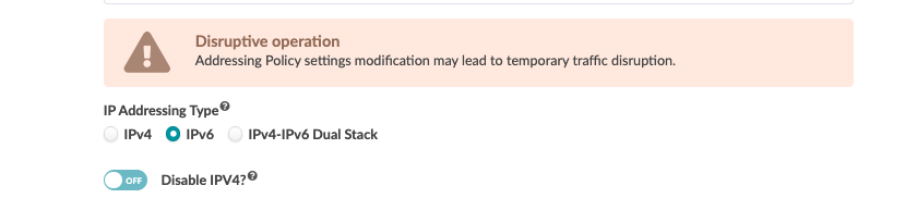
Figure 12: Routing Zone (VRF) for JCNR for a Tenant
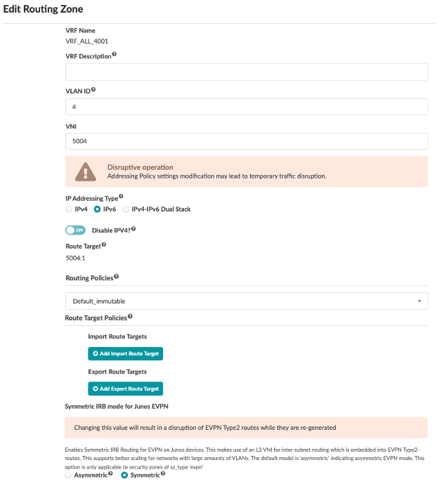
Figure 13: Routing Zone (VRF) for SR-IOV per Tenant
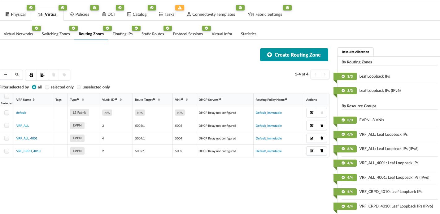
After creating the routing zone (L3 VRF), assign the loopback address by using the resource pool for each of the VRF created, as shown in Figure 14: Routing Zone for JCNR and Loopback IP Assigned per Tenant.
Figure 14: Routing Zone for JCNR and Loopback IP Assigned per Tenant
Switching Zones
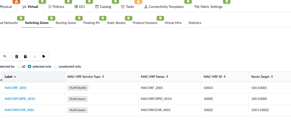
Switching zone is the EVPN MAC VRF instance that is associated to the Virtual Network for segregation of tenant layer 2 traffic. For SR-IOV, VLAN bundle is selected so as to map tenant VLANs. A tenant is assigned the SVLAN and the SVLAN can be associated with multiple CVLAN.
Table 7: Switching Zone for Each Overlay Network
| Parameters | JCNR | JCNR vRR | SR-IOV |
|---|---|---|---|
| Label | MACVRFJCNR_4000 | MACVRFCRPD_4010 | MACVRF_2001 |
| Implementation Type | mac_vrf | mac_vrf | mac_vrf |
| MAC-VRF Service Type | VLAN Aware | VLAN Aware | VLAN Bundle |
| MAC-VRF Name | MACVRFJCNR_4000 | MACVRFCRPD_4010 | MACVRF_2001 |
| MAC-VRF ID | 10001 | 10000 | 10003 |
| Route Target | 100:110001 | 100:10000 | 100:10001 |
| Virtual Networks | VN4000 | VN4010 | VN2001 |
Figure 15: Switching Zones
Virtual Networks
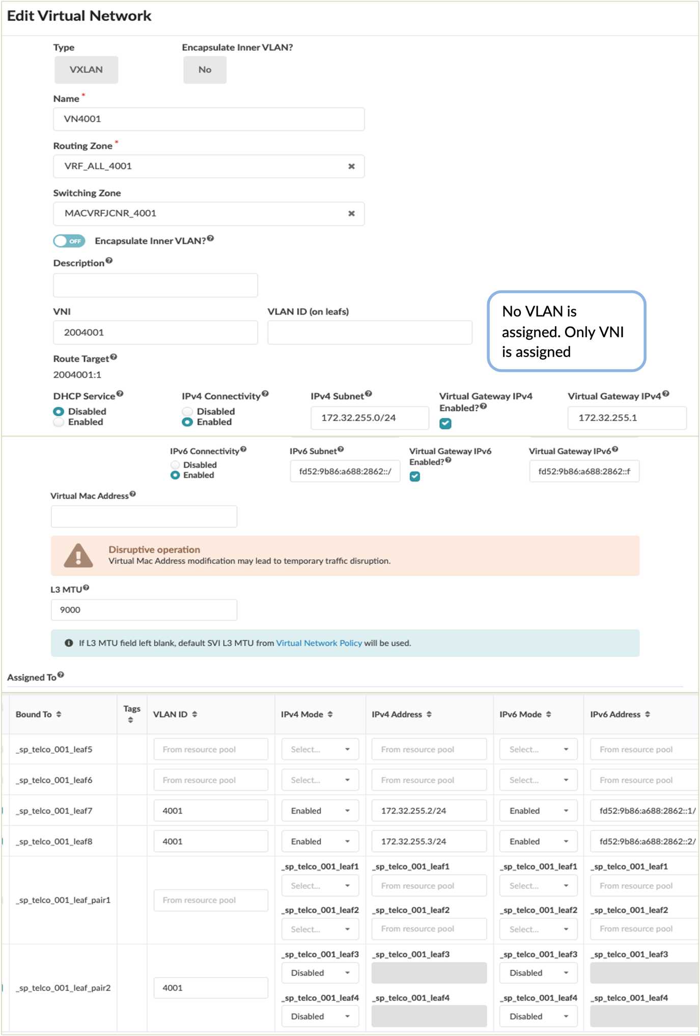
After creating the routing zone and the switching zone, virtual network is created and assigned to the relevant leaf switches. For JCNR there is no VLAN assigned only VNI is assigned as shown in the following screenshot. Here are the parameters provided for each type of Network that are needed for JCNR and SR-IOV network to be configured. In the case of SR-IOV the Encapsulate Inner VLAN is enabled to allow Q-in-Q traffic. For JCNR, Encapsulate Inner VLAN is not selected.
Table 8: Virtual Network Example
| Parameters | JCNR Virtual Network | SR-IOV Virtual Network | Virtual Route Reflector (vRR) for JCNR Network |
|---|---|---|---|
| Name | VN4000 | VN2001 | VN4010 |
| VLAN | 4000 | 2001 | 4010 |
| Type | VXLAN | VXLAN | VXLAN |
| Tags | |||
| Routing Zone | VRF_ALL | VRF_2001_3000 | VRF_CRPD_4010 |
| Switching Zone | MACVRFJCNR_4000 | MACVRF_2001 | MACVRFCRPD_4010 |
| VNI | 2004000 | 202001 | 2004010 |
| DHCP Service | Disabled | Disabled | Disabled |
| L3 MTU | 9000 | 9000 | 9000 |
| IPv4 Connectivity | Enabled | Disabled | Enabled |
| IPv4 Subnet | 172.31.255.0/24 | 193.168.255.0/24 | |
| Virtual Gateway IPv4 | 172.31.255.1 | 193.168.255.1 | |
| IPv6 Connectivity | Enabled | Disabled | Enabled |
| IPv6 Subnet | fd51:9b86:a688:2862::/64 | fdf8:db3c:29c5:ac6c::/64 | |
| Virtual Gateway IPv6 | fd51:9b86:a688:2862::ffff | fdf8:db3c:29c5:ac6c::ffff | |
| Encapsulate Inner VLAN? | No | Yes | No |
| Route Target | 2004000:1 | 202001:1 | 2004010:1 |
Note: For SR-IOV network no IPv4 or IPv6 connectivity is enabled as its purely Layer 2 with Q-in-Q encapsulation. In all the above scenarios, the leaf switch hosting the server and the border leaf switch are assigned. The border leaf switch is selected because all routing decisions are carried out on the offramp gateway which is connected to the Border leaf switch. The ‘IPv4 Connectivity’ and ‘IPv6 Connectivity’ although enabled for JCNR and vRR network can be disabled while assigning individual leaf switches, hence only border leaf switches are enabled for IRB.
As shown in Figure 16: Assigning JCNR Virtual Network to Leaf Switches, all the parameters listed above for JCNR Network VLAN 4000 is created and assigned to Border leaf switches and leaf switches hosting the server are assigned. However, the IRB is enabled only on the Border leaf switches under the section ‘Assigned to’ by selecting ‘Enabled’ for IPv4 Mode and IPv6 Mode, as for leaf switches these are ‘Disabled’.
Figure 16: Assigning JCNR Virtual Network to Leaf Switches
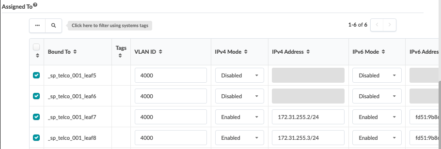
Figure 17: JCNR Virtual Network
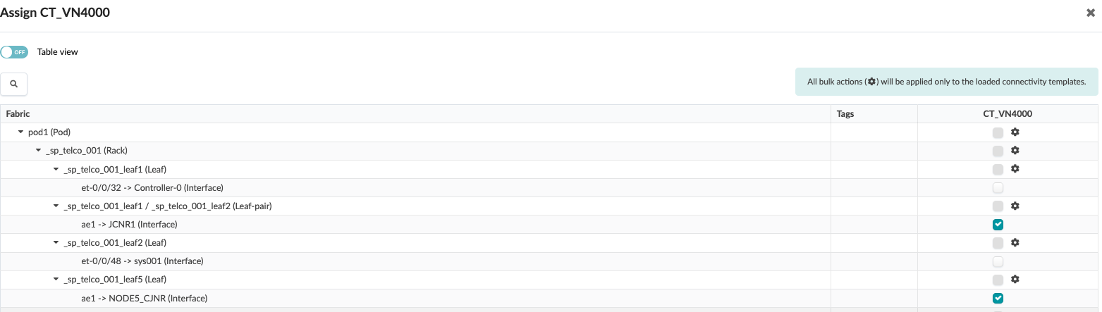
Optionally, while creating Virtual Network connectivity template can be selected. Upon selecting Connectivity template, Apstra automatically creates a connectivity template. If this option is not selected, then navigate to Blueprints → Staged → Connectivity Template and create a template with primitive Virtual Network (Single) and select the Virtual Network ID (VNI) as shown in Figure 18: Connectivity Template for Assigning VNI to Leaf Switch Interface and after saving the template, assign the template to the leaf switch interface as shown in the following. This leaf switch is selected when creating a Virtual Network.
The connectivity template is used to assign VLAN tagging on the selected leaf switch interfaces facing the JCNR hosting server.
Figure 18: Connectivity Template for Assigning VNI to Leaf Switch Interface
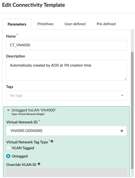
Figure 19: Assign Connectivity Template
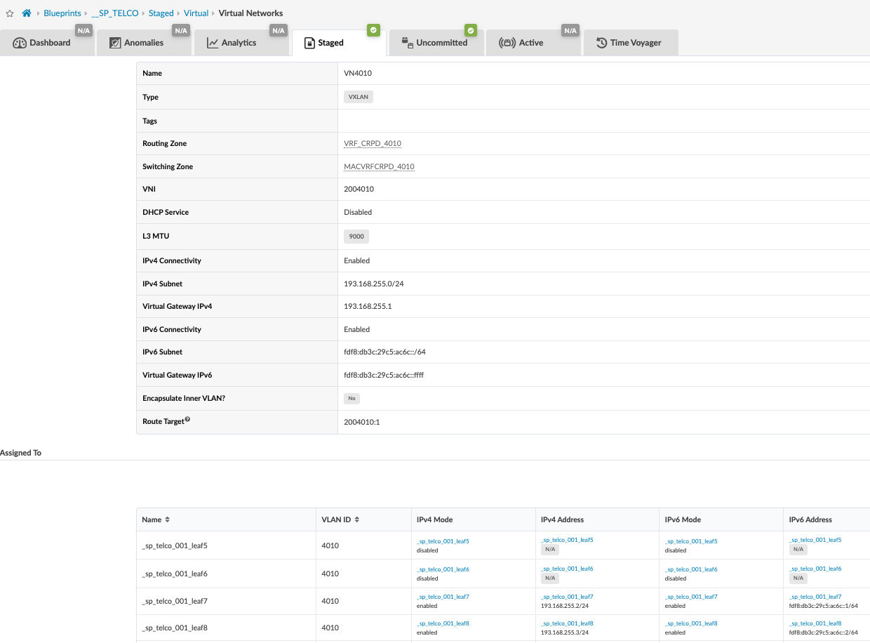
A virtual network should be created for the vRR as described in Virtual Route Reflector (vRR). The vRR control plane is formed between JCNR and offramp gateway that facilitates learning and exchanging routes that will be used to create MPLS-over-UDP tunnel from the JCNR to destination. The vRR virtual network is then assigned to the leaf switches hosting the Kubernetes controller and the Border leaf switches. However, the IRB is only enabled on the Border leaf. Apstra configure the Border leaf switches with Anycast gateway (IRB). Although the Anycast gateway is configured on the Border leaf switches it doesn’t perform inter-vrf forwarding between JCNR tenants and vRR as described in Virtual Route Reflector (vRR). The border leaf passes the traffic to off-ramp gateway to perform routing between JCNR and vRR tenants.
Figure 20: vRR Network Virtual Network
While creating the vRR virtual network, ensure that the connectivity template is enabled which automatically generates a connectivity template. A VLAN tagging is generated on the selected leaf switch interfaces facing the JCNR hosting server.
Figure 21: vRR for JCNR Traffic
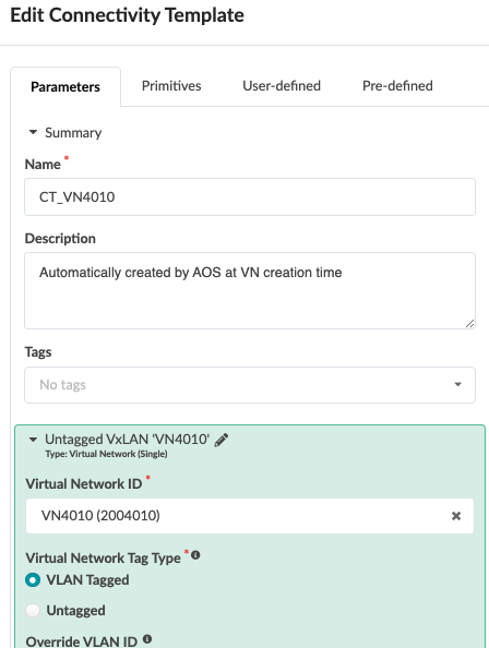
Figure 22: Assign Connectivity Template to the Leaf Switch Interfaces Facing the JCNR Controller
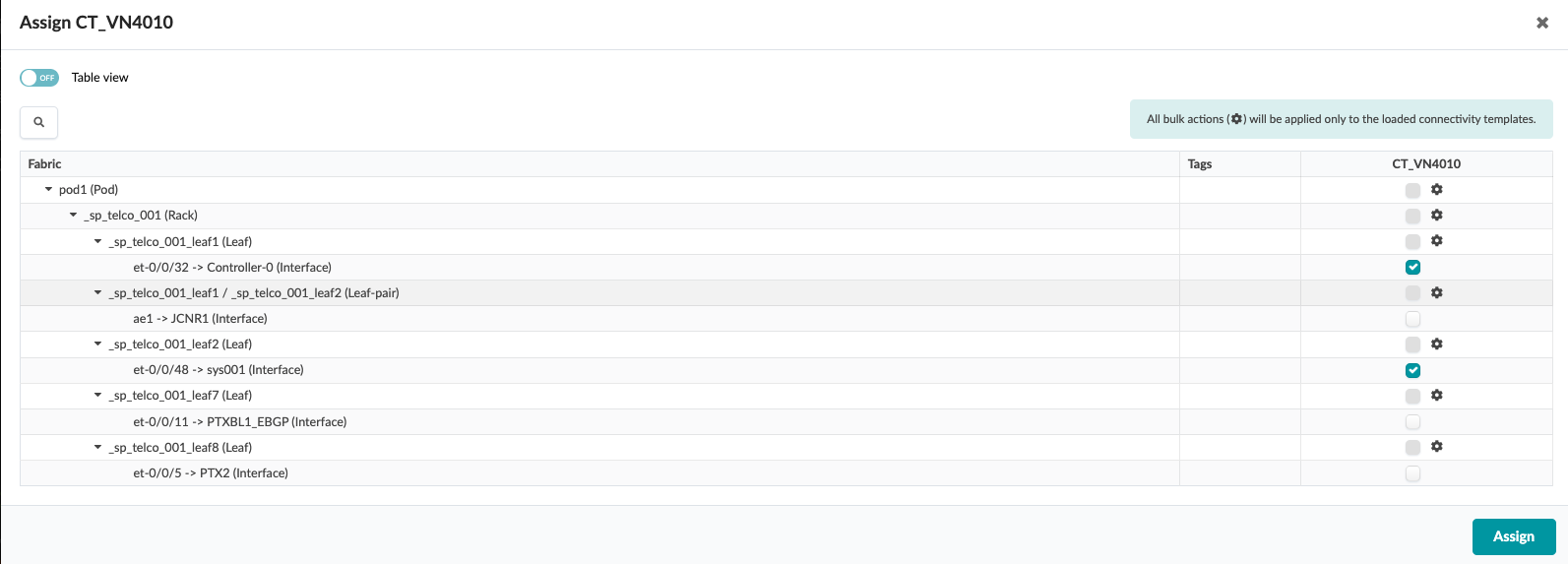
The configuration here shows the interface selected in the screenshot in Figure 22: Assign Connectivity Template to the Leaf Switch Interfaces Facing the JCNR Controller and the MAC-VRF and L3 VRF routing instance configuration applied by Apstra.
regress@sp-telco-001-leaf2> show configuration interfaces et-0/0/48
description to.sys001;
flexible-vlan-tagging;
speed 100g;
mtu 9216;
encapsulation flexible-ethernet-services;
unit 10000 {
    description to.sys001;
    family ethernet-switching {
        interface-mode trunk;
        vlan {
            members vn4010;
        }
    }
}
regress@sp-telco-001-leaf2> show configuration routing-instances
MACVRFCRPD_4010 {
    instance-type mac-vrf;
    protocols {
        evpn {
            encapsulation vxlan;
            default-gateway do-not-advertise;
            duplicate-mac-detection {
                auto-recovery-time 9;
            }
            extended-vni-list all;
            vni-options {
                vni 2004010 {
                    vrf-target target:2004010L:1;
                }
            }
        }
    }
    vtep-source-interface lo0.0 inet6;
    service-type vlan-aware;
    interface et-0/0/48.10000;
    route-distinguisher 192.168.0.3:10000;
    vrf-target target:100:10000;
    vlans {
        vn4010 {
            description VN4010;
            vlan-id 4010;
            vxlan {
                vni 2004010;
            }
        }
    }
}
 VRF_CRPD_4010 {
    instance-type vrf;
    routing-options {
        rib VRF_CRPD_4010.inet6.0 {
            multipath;
        }
        graceful-restart;
        multipath;
        auto-export;
    }
    protocols {
        evpn {
            irb-symmetric-routing {
                vni 5002;
            }
            ip-prefix-routes {
                advertise direct-nexthop;
                encapsulation vxlan;
                vni 5002;
                export BGP-AOS-Policy-VRF_CRPD_4010;
            }
        }
    }
    interface lo0.2;
    route-distinguisher 192.168.0.3:2;
    vrf-target target:5002:1;
}
Figure 23: Virtual Network for SR-IOV
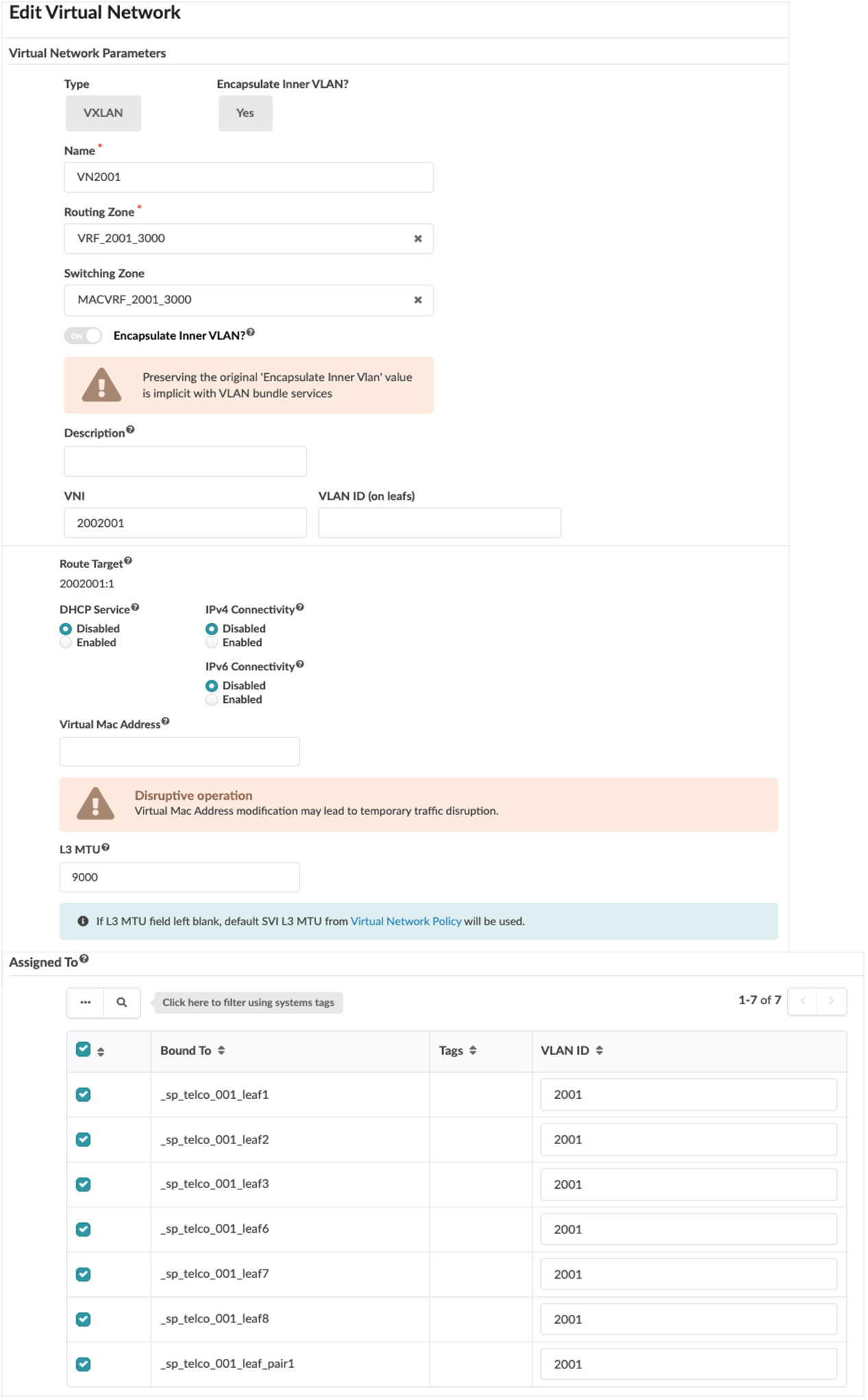
For the SR-IOV Virtual networks, one single Connectivity Template is created under Blueprints → Staged → Virtual instead of several individual connectivity templates for brevity and to consolidate per tenant. Apstra allows multiple VNIs to be assigned at once to a leaf switch interface as shown in.
Figure 24: Multiple Vnis Connectivity Template
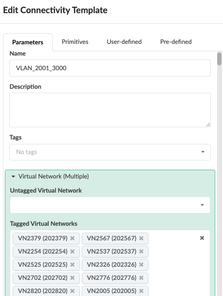
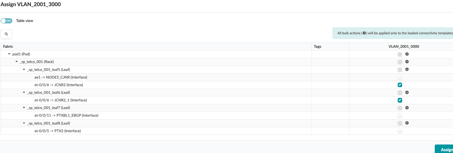
Figure 25: Assign Connectivity Template to Leaf Switch Interfaces
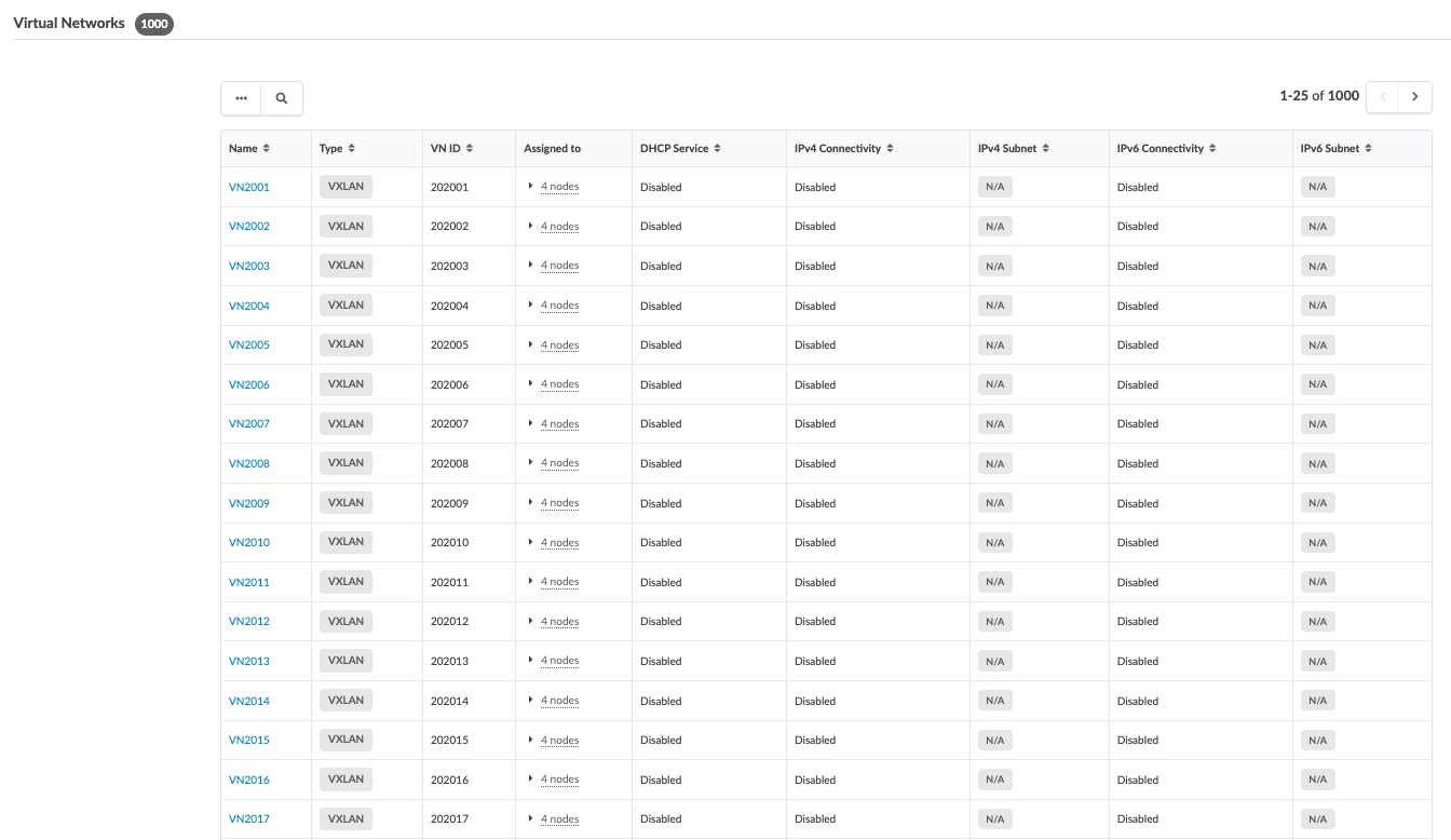
Once the virtual network is created and associated to the SR-IOV routing zone, it is visible under each Routing zone under Blueprints → Staged → Virtual → Routing Zone and select the routing zone.
Figure 26: SR-IOV Routing Zone Shows Virtual Networks Associated
The configuration applied on the leaf switches show multiple logical interfaces [edit interface unit] per tenant created with service provider style configuration using Q-in-Q encapsulation. And a corresponding MAC-VRF with VLAN bundle service type is generated as is configured in Apstra Blueprints → Staged → Switching Zone. Each of the Virtual network denotes a SR-IOV instance for the tenant.
regress@sp-telco-001-leaf5> show configuration interfaces et-0/0/6
description to.jcnr2;
flexible-vlan-tagging;
speed 100g;
mtu 9216;
encapsulation flexible-ethernet-services;
unit 2001 {
    description to.jcnr2;
    encapsulation vlan-bridge;
    vlan-id 2001;
    input-vlan-map pop;
    output-vlan-map push;
}
unit 2002 {
    description to.jcnr2;
    encapsulation vlan-bridge;
    vlan-id 2002;
    input-vlan-map pop;
    output-vlan-map push;
}
unit 2003 {
    description to.jcnr2;
    encapsulation vlan-bridge;
    vlan-id 2003;
    input-vlan-map pop;
    output-vlan-map push;
}
unit 2004 {
    description to.jcnr2;
    encapsulation vlan-bridge;
    vlan-id 2004;
    input-vlan-map pop;
    output-vlan-map push;
}
unit 2005 {
    description to.jcnr2;
    encapsulation vlan-bridge;
    vlan-id 2005;
    input-vlan-map pop;
    output-vlan-map push;
}
unit 2006 {
    description to.jcnr2;
    encapsulation vlan-bridge;
    vlan-id 2006;
    input-vlan-map pop;
    output-vlan-map push;
}
}

regress@sp-telco-001-leaf5> show configuration routing-instances
    VRF_2001_3000 {
        instance-type vrf;
        interface lo0.5;
        route-distinguisher 192.168.0.6:5;
        vrf-target target:5005:1;
        routing-options {
            multipath;
            auto-export;
            graceful-restart;
            rib VRF_2001_3000.inet6.0 {
                multipath;
            }
        }
        protocols {
            evpn {
                ip-prefix-routes {
                    advertise direct-nexthop;
                    encapsulation vxlan;
                    vni 5005;
                    export BGP-AOS-Policy-VRF_2001_3000;
                }
            }
        }
    MACVRF_2001 {
        instance-type mac-vrf;
        protocols {
            evpn {
                vni-options {
                    vni 202001 {
                        vrf-target target:202001L:1;
                    }
                }
                encapsulation vxlan;
                default-gateway do-not-advertise;
                duplicate-mac-detection {
                    auto-recovery-time 9;
                }
                extended-vni-list all;
            }
        }
        vtep-source-interface lo0.0 inet6;
        service-type vlan-bundle;
        route-distinguisher 192.168.0.6:10003;
        vrf-target target:100:10001;
        vlans {
            vn2001 {
                interface et-0/0/6.2001;
                description "VN2001";
                vxlan {
                    vni 202001;
                    decapsulate-accept-inner-vlan;
                    encapsulate-inner-vlan;
                }
            }
        }
    }
}
Apstra: Configuring Border Leaf Connectivity for JCNR Route Exchange
The Border Leaf switches connected to the Off-Ramp Gateway provide the connectivity required for exchanging JCNR loopback reachability information. JCNR loopback (lo0) addresses are selectively leaked towards the Off-Ramp Gateway to enable identification and reachability of the JCNR MPLS-over-UDP tunnel endpoints.
These loopback addresses serve as the next-hop and tunnel endpoint addresses used by the JCNR overlay. The Off-Ramp Gateway uses the learned loopback routes to establish MPLS-over-UDP reachability and forward traffic towards the appropriate JCNR instance. To limit route propagation and maintain routing scalability, only the loopback prefixes are advertised through dedicated route policies rather than the complete tenant routing table.
The Border Leaf switches provide transport reachability across the EVPN-VXLAN fabric, while the Off-Ramp Gateway uses the leaked loopback routes to perform tunnel resolution, inter-VRF policy enforcement, and forwarding towards the JCNR service endpoints.
Following are the key functions:
- Border Leaf switches provide fabric connectivity between the JCNR environment and the Off-Ramp Gateway.
- JCNR loopback (lo0) addresses identify MPLS-over-UDP tunnel endpoints.
- The off-ramp gateway learns the JCNR loopback routes through controlled route leaking and route policies.
- Loopback routes are used for tunnel endpoint resolution and VPN next-hop reachability.
- Only loopback prefixes are exchanged to minimize route distribution and preserve scalability.
To configure the border leaf switches for the above connectivity, a connectivity template is applied in Apstra to form the IP Link between the border leaf switch and the offramp gateway as shown in the following. To create a connectivity template, navigate to Blueprint → Staged → Connectivity Template. The template is then assigned to the Border leaf that is connected to the offramp gateway.
Note: For the purposes of this lab testing, only one offramp gateway and one Border leaf switch is configured. However it is recommended to have two Offramp Gateway connecting to each border leaf switch. Note: For the purposes of this lab testing, only one offramp gateway and one Border leaf switch is configured. However it is recommended to have two Offramp Gateway connecting to each border leaf switch.
Figure 27: Connectivity Template to Form IP Link Connection
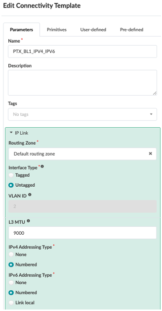
After the connectivity template is created then allocate the IPv6 addresses by navigating to Blueprint → Virtual → Routing -zones and selecting the default routing zone that was allocated on the connectivity template.
Figure 28: Allocating IP Addresses

A configlet is applied to the Border Leaf switches to selectively leak JCNR loopback routes towards the Off-Ramp Gateway. These loopback addresses identify the JCNR MPLS-over-UDP tunnel endpoints and provide the reachability required for offramp gateway-to-vRR control-plane communication and MPLS-over-UDP service operation. The off-ramp gateway establishes iBGP VPN peering with the vRR instance running within the Kubernetes cluster to exchange tenant VPN routes and service reachability information. The configlet is available on Validated Design Github in Telco Cloud directory.
The configuration shows that a dedicated eBGP peering is established for the vRR routing instance (VRF) to exchange only the JCNR loopback prefixes required for control-plane connectivity. Static routes and RIB groups are used to selectively leak the JCNR loopback addresses between the vRR VRF and the global routing table. The BGP import and export policies strictly control route advertisement. The policies ensure all incoming routes from offramp gateway are accepted using the policy RoutesFromExt-default-Default_immutable , however only the JCNR routes are exported using the EXPORT-TO-PTX policy and RoutesToExt-default-Default_immutable under [edit policy-options] ensures that the fabric or tenant routes are not advertised. This ensures that only the required JCNR node loopback routes are exchanged with the Off-Ramp Gateway and prevents unintended route leakage of tenant routes into other routing instances or the wider network. The extended-nexthop under family inet unicast border leaf switch can also advertise IPv4 unicast routes over an IPv6 BGP session using IPv6 network layer reachability information (NLRI) next-hops.
Note: The tenant routes are contained within their respective tenant VRF and hence the JCNR loopback routes are isolated from tenant routes.
VRF_CRPD_4010 {
    instance-type vrf;
    routing-options {
        rib VRF_CRPD_4010.inet6.0 {
            static { <<< static routes for JCNR/vRR loopback routes
                route fdf9:db3c:29c5:ac6c::ffff:fffe/128 next-hop fdf8:db3c:29c5:ac6c::ffff:fffe;
                route fdf9:db3c:29c5:ac6c::ffff:ffff/128 next-hop fdf8:db3c:29c5:ac6c::ffff:ffff;
            }
            multipath;
        }
        interface-routes { <<< only selected routes to be shared between routing tables instead of leaking the entire VRF routing table
            rib-group inet6 CRPD4010-TO-GLOBAL;  <<< Rib group to only share JCNR loopback routes
        }
        graceful-restart;
        multipath;
        auto-export;
    }
    protocols {
        bgp { <<< EBGP with offramp gateway to form control plane to exchange JCNR/vRR routes
            group l3rtr {
                type external;
                multihop {
                    ttl 1;
                }
                family inet {
                    unicast {
                        loops 2;
                    }
                }
                family inet6 {
                    unicast {
                        loops 2;
                    }
                }
                multipath {
                    multiple-as;
                }
                neighbor 2001:2001:2001:2001::21 {
                    description facing_sys001;
                    local-address 2001:2001:2001:2001::20;
                    import ( RoutesFromExt-default-Default_immutable );
                    family inet {
                        unicast {
                            extended-nexthop; <<< Allow advertising IPv4 routes over IPv6 NLRI next-hop
                        }
                    }
                    family inet6 {
                        unicast;
                    }
                    export [ EXPORT-TO-PTX RoutesToExt-default-Default_immutable ];
                    peer-as 64513;
                }
            }
        }
        evpn {
            irb-symmetric-routing {
                vni 5002;
            }
            ip-prefix-routes {
                advertise direct-nexthop;
                encapsulation vxlan;
                vni 5002;
                export BGP-AOS-Policy-VRF_CRPD_4010;
            }
        }
    }
    interface et-0/0/11.0;
    interface irb.4000;
    interface irb.4001;
    interface irb.4010;
    interface lo0.2;
    route-distinguisher 192.168.0.8:2;
    vrf-target target:5002:1;
}

routing-options {
rib inet.0 {
    static {
        route 192.168.255.0/24 next-table VRF_CRPD_4010.inet.0;
    }
}
rib inet6.0 {
    static {
        route fdf9:db3c:29c5:ac6c::ffff:fffe/128 next-hop fdf8:db3c:29c5:ac6c::ffff:fffe;
        route fdf9:db3c:29c5:ac6c::ffff:ffff/128 next-hop fdf8:db3c:29c5:ac6c::ffff:ffff;
    }
}
router-id 192.168.0.8;
autonomous-system 108;
graceful-restart;
rib-groups {
    CRPD4010-TO-GLOBAL {
        import-rib [ VRF_CRPD_4010.inet6.0 inet6.0 ];
        import-policy LEAK-4010-CONNECTED; <<< Import policy to filter only JCNR Fabric routes into inet6.0 table
    }
}
}
protocols {
  router-advertisement
   interface et-0/0/11.0 { <<< Interface assigned in Connectivity Template to connect to Offramp Gateway
        max-advertisement-interval 30;
        min-advertisement-interval 10;
    }
  }
}
policy-options {
 policy-statement LEAK-4010-CONNECTED {
  term IPv6-DIRECT {
      from {
           protocol direct;
           route-filter fdf8:db3c:29c5:ac6c::/64 exact;
      }
      then accept;
  }
  term REJECT {
      then reject;
   }
 }

policy-statement EXPORT-TO-PTX { <<< Export to Offramp Gw JCNR Loopback routes
    term NODE1-LO0 {
    from {
        family inet6;
        protocol static;
        route-filter fdf9:db3c:29c5:ac6c::ffff:ffff/128 exact;
        route-filter fdf9:db3c:29c5:ac6c::ffff:fffe/128 exact;
    }
    then {
        next-hop self;
        accept;
    }
  }
}

 policy-statement BGP-AOS-Policy-VRF_CRPD_4010 { <<< Apstra applies this policy natively when VRF was created
  term BGP-AOS-Policy-VRF_CRPD_4010-10 {
      from policy AllPodNetworks-VRF_CRPD_4010;
      then accept;
  }
  term BGP-AOS-Policy-VRF_CRPD_4010-100 {
      then reject;
  }
  term BGP-AOS-Policy-VRF_CRPD_4010-20 { <<< configlet modified Apstra applied policy
      from protocol bgp;
      then accept;
  }
 }

route-filter-list RoutesFromExt-default-Default_immutable {
    0.0.0.0/0 upto /32;
}
route-filter-list RoutesFromExtV6-default-Default_immutable {
    0::0/0 upto /128;
}
route-filter-list RoutesToExt-default-Default_immutable {
    192.168.0.0/29 upto /32;
    192.168.0.8/31 upto /32;
    192.168.255.0/24 exact;
}
route-filter-list RoutesToExtV6-default-Default_immutable {
    fd86:8ff:73b0:22de::/125 upto /128;
    fd86:8ff:73b0:22de::8/127 upto /128;
    fdf8:db3c:29c5:ac6c::/64 exact;
}

 policy-statement RoutesFromExt-default-Default_immutable {
  term RoutesFromExt-default-Default_immutable-10 {
    from {
        family inet;
        route-filter-list RoutesFromExt-default-Default_immutable;
    }
    then {
        community add RoutesFromExt-default-Default_immutable;
        accept;
    }
  }
  term RoutesFromExt-default-Default_immutable-20 {
    from {
        family inet6;
        route-filter-list RoutesFromExtV6-default-Default_immutable;
    }
    then {
        community add RoutesFromExtV6-default-Default_immutable;
        accept;
    }
  }
  term RoutesFromExt-default-Default_immutable-30 {
    from family inet;
    then reject;
  }
  term RoutesFromExt-default-Default_immutable-40 {
    from family inet6;
    then reject;
  }
}

 policy-statement RoutesToExt-default-Default_immutable {
   term RoutesToExt-default-Default_immutable-10 {
      from {
          family inet;
          route-filter-list RoutesToExt-default-Default_immutable;
      }
      then {
          community delete FABRIC_COMMUNITIES;
          next-hop self;
          accept;
      }
    }
    term RoutesToExt-default-Default_immutable-20 {
      from {
          family inet6;
          route-filter-list RoutesToExtV6-default-Default_immutable;
      }
      then {
          community delete FABRIC_COMMUNITIES;
          next-hop self;
          accept;
      }
   }
   term RoutesToExt-default-Default_immutable-30 {
      from family inet;
      then reject;
   }
  term RoutesToExt-default-Default_immutable-40 {
      from family inet6;
      then reject;
    }
 }
community FABRIC_COMMUNITIES members [ 0:12 0:13 0:14 0:15 .+:200.. 2....:260.. ];
community RoutesFromExt-default-Default_immutable members [ 9:20009 21001:26000 ];
community RoutesFromExtV6-default-Default_immutable members [ 9:20010 21001:26000 ];
}
Overlay Junos OS Configuration Applied by Apstra 6.2
Apstra version 6.2 introduces the ability to create blueprints using reference design option for Service Providers which allows for native service provider-style configurations and intent-based anomaly identification. Prior to version 6.2, Apstra Freeform blueprint was used to provision Service Provider data center configuration.
Flexible Ethernet Services
In the service provide style configuration, multiple logical interfaces are configured per port and [flexible-ethernet-services] encapsulation is applied per interface. These logical interfaces are then bridged into separate or same EVPN instances (MAC-VRF). From Apstra version 6.2, the service provider style is supported and Apstra renders the Virtual Network into Service Provider (SP) style configuration. Following is the configuration snippet for the overlay network.
Flexible Ethernet services is a type of encapsulation that enables a physical interface to support different types of Ethernet encapsulations at the logical interface level. Junos OS supports two different styles of configuration for switch interfaces: the service provider style and the enterprise style. Service provider style requires more configuration but provides greater flexibility. An enterprise style is easier to configure but offers less functionality. Each configuration style requires a different Ethernet encapsulation type which can be achieved using Flexible Ethernet services. A per-unit Ethernet encapsulations make it easier to customize Ethernet-based services to multiple hosts connected to the same physical interface. However, in this validated design, the encapsulation type is the same for each logical unit as is shown in the following example. For more information about Flexible Ethernet Encapsulation, see Flexible Ethernet Services Encapsulation. The logical interface is configured with [vlan-bridge] encapsulation and mapped to bridge domains i.e. MAC-VRF instance.
Service Provider Style Configuration
In the service provider style configuration, each bridge interface should be configured with features explicitly and the bridged interface should be referenced in the EVPN instance (MAC-VRF) as show in the following configuration. Each logical interface is configured with encapsulation vlan-bridgeunder [edit interface *<interface-name>* unit *<logical-unit-number>*]
regress@sp-telco-001-leaf5> show configuration interfaces et-0/0/6
description to.jcnr2;
flexible-vlan-tagging;
speed 100g;
mtu 9216;
encapsulation flexible-ethernet-services;
unit 2001 {
    description to.jcnr2;
    encapsulation vlan-bridge;
    vlan-id 2001;
    input-vlan-map pop; <<< Removes the outermost VLAN tag (2001) from the frame immediately after it enters the router.
    output-vlan-map push;
}
unit 2002 {
    description to.jcnr2;
    encapsulation vlan-bridge;
    vlan-id 2002;
    input-vlan-map pop;
    output-vlan-map push;
}
unit 2003 {
    description to.jcnr2;
    encapsulation vlan-bridge;
    vlan-id 2003;
    input-vlan-map pop;
    output-vlan-map push;
}
unit 2004 {
    description to.jcnr2;
    encapsulation vlan-bridge;
    vlan-id 2004;
    input-vlan-map pop;
    output-vlan-map push;
}
unit 2005 {
    description to.jcnr2;
    encapsulation vlan-bridge;
    vlan-id 2005;
    input-vlan-map pop;
    output-vlan-map push;
}
regress@sp-telco-001-leaf5> show configuration routing-instances
    MACVRF_2001 {
        instance-type mac-vrf;
        protocols {
            evpn {
                vni-options {
                    vni 202001 {
                        vrf-target target:202001L:1;
                    }
                }
                encapsulation vxlan;
                default-gateway do-not-advertise;
                duplicate-mac-detection { <<< detects MAC duplication especially when MAC Address flaps rapidly between two leaf switches and suppresses MAC updates for the length of time suggested for auto-recovery-time.
                    auto-recovery-time 9;
                }
                extended-vni-list all; <<< All VNIs are extended
            }
        }
        vtep-source-interface lo0.0 inet6; <<< VXLAN Tunnel End Point (VTEP) source is bound to the logical IPv6 loopback interface address
        service-type vlan-bundle; <<<< multiple VLANs can share a single MAC address (bridge) table and broadcast domain within one EVPN (MAC-VRF) instance for a tenant
        route-distinguisher 192.168.0.6:10003;
        vrf-target target:100:10001; << route target for MAC-VRF instance
        vlans {
            vn2001 {
                interface et-0/0/6.2001; <<< SP Style config denoting per VLAN logical interface that is using MAC-VRF instance.
                description "VN2001";
                vxlan {
                    vni 202001;
                    decapsulate-accept-inner-vlan; <<< to de-encapsulate and to accept original VLAN tags in VXLAN packets
                    encapsulate-inner-vlan; <<< to preserve the original VLAN tag (in the inner Ethernet packet) when performing VXLAN encapsulation.
                }
            }
        }
    }
MACVRF_2002 {
    instance-type mac-vrf;
    protocols {
        evpn {
            encapsulation vxlan;
            default-gateway do-not-advertise;
            duplicate-mac-detection {
                auto-recovery-time 9;
            }
            extended-vni-list all;
            vni-options {
                vni 202002 {
                    vrf-target target:202002L:1;
                }
            }
        }
    }
    vtep-source-interface lo0.0 inet6;
    service-type vlan-bundle;
    route-distinguisher 192.168.0.6:10004;
    vrf-target target:100:10002;
    vlans {
        vn2002 {
            description VN2002;
            interface et-0/0/6.2002;
            vxlan {
                vni 202002;
                encapsulate-inner-vlan;
                decapsulate-accept-inner-vlan;
            }
        }
    }
}
    VRF_2001_3000 {
        instance-type vrf;
        interface lo0.5;
        route-distinguisher 192.168.0.6:5;
        vrf-target target:5005:1;
        routing-options {
            multipath;
            auto-export;
            graceful-restart;
            rib VRF_2001_3000.inet6.0 {
                multipath;
            }
        }
        protocols {
            evpn {
                ip-prefix-routes {
                    advertise direct-nexthop;
                    encapsulation vxlan;
                    vni 5005;
                    export BGP-AOS-Policy-VRF_2001_3000;
                }
            }
        }
   }
IPv6 Overlay BGP Peering
In a Juniper EVPN-VXLAN fabric, VTEPs (Virtual Tunnel Endpoints) are the gateway switches, typically leaf switches, that handle the encapsulation and de-encapsulation of user traffic into VXLAN overlay tunnels. The overlay network can be IPv4 or IPv6 networks. This validated design focuses only on the IPv6 underlay with IPv6 overlay EBGP peering.
EBGP routing protocol is used in overlay peering configuration and hence the configuration is similar to the underlay configuration. The only difference being IPv6 loopback addresses are used to specify EBGP neighbors in the overlay. Another difference is that EVPN signaling is configured in the overlay configuration.
EBGP sessions between leaf and spine nodes are established using the loopback IPv6 addresses advertised by the underlay, with BGP multihop enabled. These overlay sessions carry the IPv6 prefixes corresponding to the point-to-point links between servers and leaf nodes.
Following is an example of an Apstra configuration snippet of the overlay BGP configuration between the leaf and spine devices:
protocols {
   bgp {
       group l3clos-s-evpn {
         type external;
         multihop {
            ttl 1;
            no-nexthop-change;
         }
        family evpn {
            signaling {
            loops 2;
            }
        }
        multipath {
            multiple-as;
        }
        bfd-liveness-detection {
            minimum-interval 3000;
            multiplier 3;
        }
        neighbor fd86:8ff:73b0:22de::2 {
            description facing_sp-telco-001-leaf1-evpn-overlay;
            local-address fd86:8ff:73b0:22de::1;
            family evpn {
                signaling;
            }
            export ( SPINE_TO_LEAF_EVPN_OUT );
            peer-as 102;
        }
        neighbor fd86:8ff:73b0:22de::3 {
            description facing_sp-telco-001-leaf2-evpn-overlay;
            local-address fd86:8ff:73b0:22de::1;
            family evpn {
                signaling;
            }
            export ( SPINE_TO_LEAF_EVPN_OUT );
            peer-as 103;
        }
        neighbor fd86:8ff:73b0:22de::4 {
            description facing_sp-telco-001-leaf3-evpn-overlay;
            local-address fd86:8ff:73b0:22de::1;
            family evpn {
                signaling;
            }
            export ( SPINE_TO_LEAF_EVPN_OUT );
            peer-as 104;
        }
        neighbor fd86:8ff:73b0:22de::5 {
            description facing_sp-telco-001-leaf4-evpn-overlay;
            local-address fd86:8ff:73b0:22de::1;
            family evpn {
                signaling;
            }
            export ( SPINE_TO_LEAF_EVPN_OUT );
            peer-as 105;
        }
        neighbor fd86:8ff:73b0:22de::6 {
            description facing_sp-telco-001-leaf5-evpn-overlay;
            local-address fd86:8ff:73b0:22de::1;
            family evpn {
               signaling;
            }
            export ( SPINE_TO_LEAF_EVPN_OUT );
            peer-as 106;
        }
        neighbor fd86:8ff:73b0:22de::7 {
            description facing_sp-telco-001-leaf6-evpn-overlay;
            local-address fd86:8ff:73b0:22de::1;
            family evpn {
                signaling;
            }
            export ( SPINE_TO_LEAF_EVPN_OUT );
            peer-as 107;
        }
        neighbor fd86:8ff:73b0:22de::8 {
            description facing_sp-telco-001-leaf7-evpn-overlay;
            local-address fd86:8ff:73b0:22de::1;
            family evpn {
                signaling;
            }
            export ( SPINE_TO_LEAF_EVPN_OUT );
            peer-as 108;
        }
        neighbor fd86:8ff:73b0:22de::9 {
            description facing_sp-telco-001-leaf8-evpn-overlay;
            local-address fd86:8ff:73b0:22de::1;
            import ( DrainEvpn );
            family evpn {
                signaling;
            }
            export ( DrainEvpn );
            peer-as 109;
        }
        vpn-apply-export;
       }
   }
}
CRB Proxy MAC Option for Bridged Overlay Fabric
In an EVPN Bridged Overlay (BO) environment, the leaf switches act strictly as L2 gateways and do not possess local Layer 3 context or IRB interfaces and hence don’t participate in ARP and NDP operations by default. The ARP request packets or NDP solicitation packets are sent as broadcast traffic by the IP fabric. To avoid this ARP and NDP broadcast traffic, configure the crb-proxy-mac option on the leaf devices as the Spine devices (QFX5230-64CD) are running Junos OS Evolved.
set protocols l2-learning crb-proxy-mac family inet <MAC address>
set protocols l2-learning crb-proxy-mac family inet6 <MAC address>
With crb-proxy-mac set, the leaf devices learn MAC-IP information from the transit traffic and use EVPN Type 2 routes to update other EVPN leaf devices. The leaf devices can reply to ARP request packets or NDP solicitation packets from their connected hosts. Apstra 6.2 sets this configuration natively. Following is the configuration applied to the leaf switches.
root@LEAF5> show configuration protocols l2-learning
telemetry {
    enable-remote-entries;
}
crb-proxy-mac {
    family {
        inet {
            02:fb:00:00:00:07; <<< Any unused MAC Address
        }
        inet6 {
            02:fb:00:00:00:07; <<< Any unused MAC Address
        }
    }
}
Note: When choosing an unused MAC address for a Bridged Overlay (BO) leaf switch, use locally administered address whose first octet of the MAC address ends in 2, 6, A, or E (for example: 02:xx:xx…, 12:xx:xx…, 4e:xx:xx…). This marks the address space as private/locally managed, meaning it won’t conflict with globally registered hardware MACs (OUI assigned to vendors). All leaf switches are configured with
crb-proxy-macwith separate unused MAC address.
Apstra Freeform: Deployment and Configuration of Offramp Gateway
The Off-Ramp Gateway is deployed outside the EVPN-VXLAN fabric and serves as the interconnection point between the data center fabric, external networks, and cloud environments. The gateway is responsible for providing Layer 3 connectivity beyond the fabric boundary and acts as the central routing point for tenant services. By positioning the Off-Ramp Gateway outside the fabric, the EVPN-VXLAN data center fabric remains focused on tenant transport and isolation, while centralized routing, policy enforcement, and external network integration are handled by the gateway. This creates a clear separation between the data center transport fabric and the service routing functions required to support hybrid telco cloud deployments.
For the purposes of this design, Apstra Freeform is used to provision the Offramp Gateway as this is not natively supported using the Data Center reference architecture. Using Terraform scripts, a separate Apstra Freeform Blueprint is created to provision offramp gateway. To deploy off-ramp gateway in Apstra Terraform scripts were used to deploy Freeform Blueprint for Off-ramp gateway. The objective of the scripts is to help get started and can be modified as per requirement. For more information about Apstra freeform, see Apstra user guide. However, it’s mandatory to use the Data Center reference design architecture for deploying the Fabric.
Note: The terraform scripts for Apstra Freeform are outside the scope of this validated design. However, if these scripts are needed to deploy PTX10002-36QDD as Offramp-gateway as is described in this Validated Solution design, then contact HPE Juniper Networking or your HPE Juniper Networking account representative.
Thorough testing and validation is necessary if this script is used to deploy Production network.
Junos OS Configuration Applied on the Offramp Gateway Using Apstra Freeform
This section explains key decisions and features used to configure the offramp gateway. For full configuration, see Validated Design Github in Telco Cloud directory.
Offramp Gateway Connectivity and Tunnel Configuration
To create connectivity between the border leaf and the offramp gateway as covered in section Apstra: Configuring Border Leaf Connectivity for JCNR Route Exchange where a connectivity template was applied to create the IP Link on Border leaf switch. In the case of offramp gateway, PTX10002-36QDD is connected to the border leaf gateway.
interfaces {
    et-0/0/11 {
        speed 100g;
        unit 0 {
            family inet6 {
                address 2001:2001:2001:2001::101/127;
            }
        }
    }
  }
For the JCNR traffic, a dedicated interface Flexible-tunnel interface (fti) is configured to transport MPLS-over-UDP traffic between the JCNR and the Off-Ramp Gateway. The FTI provides a logical tunnel endpoint capable of encapsulating and terminating MPLS, IPv4, and IPv6 traffic over UDP, making it well suited for cloud-native and containerized routing environments. In this implementation, fti0.1 is configured with UDP encapsulation (encapsulation UDP) and enabled for tunnel termination. Traffic forwarded through the interface is encapsulated within UDP packets, allowing MPLS services to traverse IP-based transport networks without requiring a native MPLS underlay. For more information on this interface, see flexible tunnel interfaces guide.
The tunnel source address is configured using the JCNR loopback (lo0) address, which provides a stable endpoint for tunnel establishment and BGP peering. A dedicated payload port profile (jcnr) is associated with the interface to define the UDP destination ports used for encapsulating various payload types, including MPLS, IPv4, IPv6, and ISO traffic.
The FTI is enabled for different payload traffic allows the containerized router (JCNR) to exchange core routing information with other routers:
- IPv4 forwarding (family inet)
- IPv6 forwarding (family inet6)
- MPLS forwarding (family mpls)
- IS-IS routing packets
This allows the interface to transport VPN services and control-plane traffic carried over the MPLS-over-UDP overlay.
interfaces {
    fti0 {
        unit 1 {
            tunnel {
                encapsulation udp {
                    tunnel-termination;
                    source {
                        address fd86:8ff:73b0:22de::b;
                    }
                    payload-port-profile jcnr;
                }
            }
            family inet {
                address 172.31.255.1/32;
            }
            family inet6 {
                address fd86:8ff:73b0:22df::ffff/128;
            }
            family mpls;
        }
    }
    lo0 {
        unit 0 {
            family inet {
                address 192.168.255.11/32;
            }
            family inet6 {
                address fd86:08ff:73b0:22de::b/128;
            }
        }
    }
}
 forwarding-options {
    tunnels {
        udp {
            payload-port-profile {
                jcnr;
                inet 6636;
                inet6 6637;
                mpls 6635;
                iso 6638;
            }
        }
    }
}
Physical Loopback (Dummy Interface) Requirement
In the beginning of this document in section Off-ramp Gateway it was suggested that a “physical loopback’ construct is used to facilitate the termination of the q-in-q traffic on offramp gateway instead of the border leaf due to the limitation of the IRB feature.
From an implementation perspective, this approach simplifies the Apstra fabric configuration as the Border Leaf configuration remains largely aligned with standard Apstra fabric constructs, while the Off-Ramp Gateway performs the required traffic transition between Layer 2 and Layer 3 services.
As shown by the LLDP neighbor information, two interfaces on the Off-Ramp Gateway (sp-jvd-ptx10002-01.englab.juniper.net) are interconnected to form a physical loopback construct. This loopback is used to bridge the Layer 3 VPN domain and the Layer 2 EVPN-VXLAN domain required for SR-IOV services.
One interface is dedicated to Q-in-Q Layer 2 service termination, while the other provides Layer 3 tenant gateway services. The physical loopback enables traffic to transition between these domains, addressing the current limitation whereby Q-in-Q services cannot be terminated directly on IRB interfaces when the Off-Ramp Gateway is reached through an intermediate Layer 3 network.
From the following configuration, the interface et-0/0/34 is used to terminate Q-in-Q SR-IOV VLAN bundles. While on the interface et-0/0/35,each logical unit on the interface is associated with a tenant-specific Service VLAN (S-VLAN) and Customer VLAN (C-VLAN) combination and provides Layer 3 connectivity into the corresponding tenant VRF. For instance, the configuration statement vlan-tags outer 0x8100.2001 inner 0x8100.200defines a Q-in-Q service where Service VLAN (S-VLAN) 2001 identifies the tenant service and Customer VLAN (C-VLAN) 200 identifies a specific tenant network. The Off-Ramp Gateway terminates the double-tagged Ethernet frames on a dedicated logical interface and maps them to the appropriate tenant VRF, enabling Layer 3 gateway services and tenant isolation for SR-IOV workloads.
To provide resilient gateway services, Virtual Router Redundancy Protocol (VRRP) is configured on the Layer 3 interfaces associated with each tenant network. The VRRP virtual IP address is presented to workloads as the default gateway, ensuring consistent gateway reachability. This approach enables highly available Layer 3 services for SR-IOV workloads while maintaining strict tenant separation and integration with the EVPN-VXLAN fabric.
regress@sp-jvd-ptx10002-01> show lldp neighbors
Local Interface    Parent Interface    Chassis Id                               Port info          System Name
et-0/0/11          -                   00:cc:34:35:c8:f5                        et-0/0/11           sp-telco-001-leaf7.englab.juniper.net
et-0/0/14          -                   00:cc:34:35:c8:f5                        et-0/0/15           sp-telco-001-leaf7.englab.juniper.net
et-0/0/10          -                   00:cc:34:35:e6:f5                        et-0/0/11           sp-telco-001-leaf8.englab.juniper.net
et-0/0/15          -                   00:cc:34:35:e6:f5                        et-0/0/16           sp-telco-001-leaf8.englab.juniper.net
et-0/0/4           -                   00:cc:34:35:e6:f5                        et-0/0/4            sp-telco-001-leaf8.englab.juniper.net
re0:mgmt-0         -                   64:ac:2b:2f:9b:00                        ge-0/0/12           hmlsw133
et-0/0/35          -                   f0:d3:2b:e6:f3:16                        et-0/0/34           sp-jvd-ptx10002-01.englab.juniper.net
et-0/0/34          -                   f0:d3:2b:e6:f3:16                        et-0/0/35           sp-jvd-ptx10002-01.englab.juniper.net


configuration of interfaces
interfaces {
        et-0/0/34 {
        description " Tenant1 SVLAN EVPN egress";
        flexible-vlan-tagging;
        speed 100g;
        mtu 9000;
        encapsulation extended-vlan-bridge;
        unit 2001 {
            description "Tenant1 SVLAN SR-IOV egress";
            vlan-id 2001;
            input-vlan-map pop;
            output-vlan-map push;
        }
        unit 2002 {
            description " Tenant2 SVLAN SR-IOV egress";
            vlan-id 2002;
            input-vlan-map pop;
            output-vlan-map push;
        }
    }
    et-0/0/35 {
        description "Interface for L3 VRF ingress ";
        flexible-vlan-tagging;
        speed 100g;
        mtu 9000;
        encapsulation flexible-ethernet-services;
        unit 1 {
            description "Interface to terminate Tenant1 SR-IOV VN1";
            vlan-tags outer 0x8100.2001 inner 0x8100.100;
            family inet {
                address 10.201.255.1/24 {
                    vrrp-group 1 {
                        virtual-address 10.201.255.254;
                        accept-data;
                    }
                }
            }
            family inet6 {
                address 2001::10:201:255:1/112 {
                    vrrp-inet6-group 1 {
                        virtual-inet6-address 2001::10:201:255:ffff;
                        accept-data;
                    }
                }
            }
        }
        unit 2 {
            description "Interface to terminate Tenant1 SR-IOV VN2";
            vlan-tags outer 0x8100.2001 inner 0x8100.200;
            family inet {
                address 10.202.255.1/24 {
                    vrrp-group 2 {
                        virtual-address 10.202.255.254;
                        accept-data;
                    }
                }
            }
            family inet6 {
                address 2001::10:202:255:1/112 {
                    vrrp-inet6-group 2 {
                        virtual-inet6-address 2001::10:202:255:ffff;
                        accept-data;
                    }
                }
            }
        }
        unit 3 {
            description "Interface to terminate Tenant2 SR-IOV VN1";
            vlan-tags outer 0x8100.2002 inner 0x8100.100;
            family inet {
                address 10.211.255.1/24 {
                    vrrp-group 1 {
                        virtual-address 10.211.255.254;
                        accept-data;
                    }
                }
            }
            family inet6 {
                address 2001::10:211:255:1/112 {
                    vrrp-inet6-group 1 {
                        virtual-inet6-address 2001::10:211:255:ffff;
                        accept-data;
                    }
                }
            }
        }
    }
}
Configuring Tenant VRFs for SR-IOV and JCNR Networks
The Off-Ramp Gateway hosts dedicated VRFs for JCNR and SR-IOV services.
For the tenant SR-IOVs, a virtual switch is used to provide the Layer 2 domain for the SRIOV SVLANs. A virtual switch is a Layer 2 switching instance that can be used as a layer 2 bridging domain with one or more VLANs. Each virtual-switch instance is associated with a tenant-specific SVLAN and bridges traffic between the relevant interfaces. These Layer 2 forwarding domains are used to transport tenant SRIOV traffic and are connected to the corresponding tenant Layer 3 VRFs on the offramp gateway through the physical loopback construct.
routing-instances {
    vrf-t1-sriov-vns {
        instance-type virtual-switch;
        description "SRIOV Tenant1 VLANs";
        vlans {
            vlan-t1-sriov-svlan {
                interface et-0/0/34.2001;
          interface et-0/0/14.2001;
            }
        }
    }
    vrf-t2-sriov-vns {
        instance-type virtual-switch;
         description "SRIOV Tenant2 VLANs";
        vlans {
            vlan-t2-sriov-svlan {
                interface et-0/0/34.2002;
          interface et-0/0/14.2002;
            }
        }
    }
The vrf-t1-sriov-vn1 routing instance provides Layer 3 services for Tenant 1 Virtual Network 1. The VRF is associated with the Layer 3 gateway interface terminating the corresponding Q-in-Q VLAN bundle, and a dedicated loopback interface used for routing and control-plane functions. Import and export policies, together with VPN route-targets, control route distribution and maintain tenant isolation. Similarly, vrf-t1-sriov-vn2 routing instance provides Layer 3 services for Tenant 1 Virtual Network 2. And the import policies allow for route leaking between the Tenant 1 Virtual Network 2 and Virtual Network 1 for the same tenant. Similarly, the routing-instance vrf-t2-sriov-vn1 provides Layer 3 services for Tenant 2 Virtual Network 1.
vrf-t1-sriov-vn1 {
    instance-type vrf;
    routing-options {
        rib vrf-t1-sriov-vn1.inet6.0;
        auto-export {
            family inet6 {
                unicast;
            }
        }
    }
    interface et-0/0/35.1;
    interface lo0.100;
    vrf-import import-vrf-t1-sriov-vn1;
    vrf-export EXPORT_SRIOV;
    vrf-target {
        target:4200000001L:20011;
        import target:4200000002L:1001;
    }
    vrf-table-label;
}
vrf-t1-sriov-vn2 {
    instance-type vrf;
    routing-options {
        auto-export {
            family inet {
                unicast;
            }
            family inet6 {
                unicast;
            }
        }
    }
    interface et-0/0/35.2;
    vrf-import [ t1v2-import leak-t1v1-to-t1v2 ];
    vrf-target target:4200000001L:20012;
    vrf-table-label;
}
vrf-t2-sriov-vn1 {
    instance-type vrf;
    routing-options {
        auto-export {
            family inet {
                unicast;
            }
            family inet6 {
                unicast;
            }
        }
    }
    interface et-0/0/35.3;
    vrf-import [ t2v1-import leak-t1v1-to-t2v1 ];
    vrf-target target:4200000001L:20021;
    vrf-table-label;
}
}
The vrf-t1-jcnr-ocp-vn1 routing instance provides Layer 3 connectivity for Tenant 1 JCNR-hosted workloads and participates in MPLS-over-UDP VPN services using a dedicated loopback interface. Controlled route leaking is implemented through import and export policies, allowing selective exchange of routes between the JCNR and SR-IOV VRFs while maintaining tenant isolation. The vrf-t1-jcnr-ol-vn1 routing instance provides the overlay service context used by JCNR for tenant VPN and MPLS-over-UDP connectivity.
routing-instances {
     vrf-t1-jcnr-ocp-vn1 {
        instance-type vrf;
        routing-options {
            rib vrf-t1-jcnr-ocp-vn1.inet6.0;
            auto-export {
                family inet6 {
                    unicast;
                }
            }
        }
        interface lo0.1;
        vrf-import leak-sriov-to-jcnr;
        vrf-export export-jcnr-vrf;
        vrf-target {
            target:4200000002L:1001;
            import target:4200000001L:20011;
        }
        vrf-table-label;
    }
    vrf-t1-jcnr-ol-vn1 {
        instance-type vrf;
        interface lo0.11;
        vrf-target target:4200000001L:11;
    }
 }
Selective Route Leaking
The configuration also configures rib-groups to selectively leak only the tenant loopback addresses from global routing table to tenant routing tables under edit routing-options rib-groups statement. For JCNR to SR-IOV traffic, route leaking policy of specific JCNR fabric subnet is performed under edit policy-options. The dynamic-tunnels statement refers to the dynamic MPLS-over-UDP tunnel configuration to establish connectivity with JCNR instances and uses the offramp gateway loopback address as source address.
routing-options {
    rib inet.0;
    rib inet6.0 {
        static {
            route ::/0 next-hop 2001:db8:1::1;
            route 2001::10:201:255:0/112 discard;
            route 2001::10:201:255:4/128 next-table vrf-t1-sriov-vn1.inet6.0;
        }
    }
    interface-routes {
        rib-group inet6 LEAK-INET6;
        family inet6 {
            export {
                lan;
            }
        }
    }
    router-id 192.168.255.11;
    route-distinguisher-id-use-router-id;
    autonomous-system 64513;
    rib-groups {
        loopback-to-fabrics {
            import-rib [ inet6.0 vr-t1-jcnr-fabric.inet6.0 ];
            import-policy loopbacks-only;
        }
        default-reject {
            import-rib [ inet.0 vr-t1-jcnr-fabric.inet.0 ];
            import-policy default-reject;
        }
        LEAK-INET6 {
            import-rib [ inet6.0 vrf-t1-sriov-vn1.inet6.0 ];
            import-policy LEAK-FD51;
        }
    }
    dynamic-tunnels {
        t1-jcnr-fabric {
            source-address fd86:8ff:73b0:22de::b;
            udp;
            destination-networks {
                fd01:976b:d604:2006::/64;
            }
        }
        ocp-jcnr-fabric {
            source-address fd86:8ff:73b0:22de::b;
            udp;
            destination-networks {
                fd51:9b86:a688:2862::/64;
            }
        }
    }
    forwarding-table {
        export PPLB;
    }
}
BGP Sessions to Advertise Routes
BGP protocol is configured to perform two control plane functions:
- The Off-Ramp Gateway establishes an eBGP session with the Border Leaf switches to exchange loopback addresses used for MPLS-over-UDP tunnel establishment. The routes learned from border leaf switches are automatically placed into the primary table (
inet6.0) and immediately replicated to the secondary tables defined in the rib-groupLEAK-INET6as discussed in previous section``Selective Route Leaking.
protocols {
    bgp {
        group EBGP_TO_BL1 {
            type external;
            family inet6 {
                unicast {
                    rib-group LEAK-INET6;
                }
            }
            peer-as 106;
            multipath {
                multiple-as;
            }
            neighbor 2001:2001:2001:2001::100 { <<< Border leaf loopback address
                export EXPORT_Lo0;
            }
        }
}- The offramp gateway establishes an IBGP Session with the JCNR Controller (vRR) to exchange the JCNR routes. The export policy is used to advertise selective SR-IOV routes to JCNR instances by applying the JCNR route target to tag the routes. This ensures only the selected routes are advertised maintaining tenant isolation.
protocols {
    bgp {
        group client {
            type internal;
            local-address fd86:8ff:73b0:22de::b;
            family inet-vpn {
                unicast {
                    extended-nexthop; <<< to allow IPv4 routes over IPv6
                }
            }
            family inet6-vpn {
                unicast {
                    extended-nexthop-tunnel;
                }
            }
            export add-jcnr-rt-to-sriov;
            local-as 4200000001;
            multipath;
            neighbor fdf8:db3c:29c5:ac6c::ffff:ffff;
            vpn-apply-export;
        }
    }
}
Compute Install and Deployment of Ubuntu Operating System, Kubernetes
The compute infrastructure provides the hosting platform for Kubernetes, JCNR, and SR-IOV workloads. Prior to deploying cloud-native services, the servers must be prepared with a supported operating system, appropriate hardware settings, and Kubernetes components. For this setup, both SR-IOV and JCNR are used and hence all commands and setup used applied here apply to all servers.
Note: The deployment steps described in this document are based on the HPE and Dell server platforms used in the lab, which provides high level overview of packages, configurations, and dependencies. Actual deployment procedures may vary depending on the server hardware, operating system version, network topology, and architectural requirements of a given environment. For production setup, proper due diligence should be performed before proceeding with these steps.
Prerequisite Steps Required for All Servers
- Ensure physical host (for example, HPE server) has SR-IOV and Intel VT-d enabled in System BIOS. On HPE DL360 server, using the steps, enable the SR-IOV function from the BIOS, see HPE ProLiant server related configuration:
Boot into system utilities by pressing F9.
From the System Utilities screen, select System Configuration -> BIOS/Platform Configuration (RBSU) -> System Options -> Virtualization Options -> SR-IOV and press Enter.

Enabling or disabling Intel VT-d
From the System Utilities screen, select System Configuration > BIOS/Platform Configuration (RBSU) > System Options > Virtualization Options > Intel (R) VT-d and press Enter.
Select a setting and press Enter.
Enabled—Enables a hypervisor or operating system supporting this option to use hardware capabilities provided by Intel’s Virtualization Technology for directed I/O.
Disabled—Does not enable a hypervisor or operating system supporting this option to use hardware capabilities provided by Intel’s Virtualization Technology for directed I/O.
Press F10.- Ensure the server OS on the nodes is Ubuntu 22.04 and higher.
root@master1:~# lsb_release -a
No LSB modules are available.
Distributor ID:    Ubuntu
Description:   Ubuntu 22.04.5 LTS
Release:   22.04
Codename:  jammy

 root@master1:~# cat /etc/os-release
PRETTY_NAME="Ubuntu 22.04.5 LTS"
NAME="Ubuntu"
VERSION_ID="22.04"
VERSION="22.04.5 LTS (Jammy Jellyfish)"
VERSION_CODENAME=jammy
ID=ubuntu
ID_LIKE=debian
HOME_URL="https://www.ubuntu.com/"
SUPPORT_URL="https://help.ubuntu.com/"
BUG_REPORT_URL="https://bugs.launchpad.net/ubuntu/"
PRIVACY_POLICY_URL="https://www.ubuntu.com/legal/terms-and-policies/privacy-policy"
UBUNTU_CODENAME=jammy- Verify NIC details (for SR-IOV).
root@master1:~# lspci | grep -i net
04:00.0 Ethernet controller: Broadcom Inc. and subsidiaries NetXtreme BCM5720 Gigabit Ethernet PCIe
04:00.1 Ethernet controller: Broadcom Inc. and subsidiaries NetXtreme BCM5720 Gigabit Ethernet PCIe
32:00.0 Ethernet controller: Intel Corporation Ethernet Controller X710 for 10GbE SFP+ (rev 02)
32:00.1 Ethernet controller: Intel Corporation Ethernet Controller X710 for 10GbE SFP+ (rev 02)
32:00.2 Ethernet controller: Intel Corporation Ethernet Controller X710 for 10GbE SFP+ (rev 02)
32:00.3 Ethernet controller: Intel Corporation Ethernet Controller X710 for 10GbE SFP+ (rev 02)
4b:00.0 Ethernet controller: Intel Corporation Ethernet Controller E810-XXV for SFP (rev 02)
4b:00.1 Ethernet controller: Intel Corporation Ethernet Controller E810-XXV for SFP (rev 02)
b1:00.0 Ethernet controller: Intel Corporation Ethernet Controller X710 for 10GbE SFP+ (rev 02)
b1:00.1 Ethernet controller: Intel Corporation Ethernet Controller X710 for 10GbE SFP+ (rev 02)
b1:00.2 Ethernet controller: Intel Corporation Ethernet Controller X710 for 10GbE SFP+ (rev 02)
b1:00.3 Ethernet controller: Intel Corporation Ethernet Controller X710 for 10GbE SFP+ (rev 02)- The following command list All NICs. For nodes hosting SR-IOV it lists the Virtual Functions that are created which will be configured later.
Nodes not running SR-IOV
root@master1:~# lshw -C net -businfo
Bus info          Device      Class          Description
========================================================
pci@0000:04:00.0  eno8303     network        NetXtreme BCM5720 Gigabit Ethernet PCIe
pci@0000:04:00.1  eno8403     network        NetXtreme BCM5720 Gigabit Ethernet PCIe
pci@0000:32:00.0  eno12399    network        Ethernet Controller X710 for 10GbE SFP+
pci@0000:32:00.1  eno12409    network        Ethernet Controller X710 for 10GbE SFP+
pci@0000:32:00.2  eno12419    network        Ethernet Controller X710 for 10GbE SFP+
pci@0000:32:00.3  eno12429    network        Ethernet Controller X710 for 10GbE SFP+
pci@0000:4b:00.0  enp75s0f0   network        Ethernet Controller E810-XXV for SFP
pci@0000:4b:00.1  enp75s0f1   network        Ethernet Controller E810-XXV for SFP
pci@0000:b1:00.0  enp177s0f0  network        Ethernet Controller X710 for 10GbE SFP+
pci@0000:b1:00.1  enp177s0f1  network        Ethernet Controller X710 for 10GbE SFP+
pci@0000:b1:00.2  enp177s0f2  network        Ethernet Controller X710 for 10GbE SFP+
pci@0000:b1:00.3  enp177s0f3  network        Ethernet Controller X710 for 10GbE SFP+
Node running SR-IOV shows associated Virtual Function
root@node3:~# lshw -C net -businfo
Bus info          Device       Class          Description
=========================================================
pci@0000:04:00.0  eno8303      network        NetXtreme BCM5720 Gigabit Ethernet PCIe
pci@0000:04:00.1  eno8403      network        NetXtreme BCM5720 Gigabit Ethernet PCIe
pci@0000:17:00.0  enp23s0f0    network        Ethernet Controller E810-XXV for SFP
pci@0000:17:00.1  enp23s0f1    network        Ethernet Controller E810-XXV for SFP
pci@0000:32:00.0               network        Ethernet Controller X710 for 10GbE SFP+
pci@0000:32:00.1  eno12409     network        Ethernet Controller X710 for 10GbE SFP+
pci@0000:32:00.2               network        Ethernet Controller X710 for 10GbE SFP+
pci@0000:32:00.3  eno12429     network        Ethernet Controller X710 for 10GbE SFP+
pci@0000:32:0e.0               network        Ethernet Virtual Function 700 Series
pci@0000:32:0e.1               network        Ethernet Virtual Function 700 Series
pci@0000:32:0e.2  eno12429v2   network        Ethernet Virtual Function 700 Series
pci@0000:32:0e.3               network        Ethernet Virtual Function 700 Series
pci@0000:32:0e.4  eno12429v4   network        Ethernet Virtual Function 700 Series
pci@0000:32:0e.5  eno12429v5   network        Ethernet Virtual Function 700 Series
pci@0000:32:0e.6  eno12429v6   network        Ethernet Virtual Function 700 Series
pci@0000:32:0e.7               network        Ethernet Virtual Function 700 Series
pci@0000:32:0f.0  eno12429v8   network        Ethernet Virtual Function 700 Series
pci@0000:32:0f.1  eno12429v9   network        Ethernet Virtual Function 700 Series
pci@0000:32:0f.2               network        Ethernet Virtual Function 700 Series
pci@0000:32:0f.3  eno12429v11  network        Ethernet Virtual Function 700 Series
pci@0000:32:0f.4               network        Ethernet Virtual Function 700 Series
pci@0000:32:0f.5               network        Ethernet Virtual Function 700 Series
pci@0000:32:0f.6  eno12429v14  network        Ethernet Virtual Function 700 Series
pci@0000:32:0f.7               network        Ethernet Virtual Function 700 Series
pci@0000:b1:00.0  enp177s0f0   network        Ethernet Controller X710 for 10GbE SFP+
pci@0000:b1:00.1  enp177s0f1   network        Ethernet Controller X710 for 10GbE SFP+
pci@0000:b1:00.2  enp177s0f2   network        Ethernet Controller X710 for 10GbE SFP+
pci@0000:b1:00.3 enp177s0f3 network Ethernet Controller X710 for 10GbE SFP+- Configure persistent boot-time kernel actions. Without setting up a persistent, automated boot-time routine, the underlying host network interface cards (NICs) cannot safely communicate with the high-performance Juniper vRouter. Create the systemd
rc-local.servicethis ensures that when the host reboots, the hardware interfaces are automatically placed into the exact high-performance mode that the Juniper Cloud Native Router expects before the Kubernetes pods try to initialize. Then populate the execution script to configure kernel space modules for virtual functions:
modprobe vfio-pci vfio Forces the Linux kernel to load the Virtual Function I/O driver. This driver allows JCNR to bypass the standard kernel network stack and directly control the network hardware for line-rate speeds. allow_unsafe_interrupts=1 Enables high-performance packet processing even if the physical motherboard/CPU doesn’t have strict hardware-enforced interrupt isolation (or if it is shared). Without this, the kernel will block the DPDK application from starting. enable_unsafe_noiommu_mode Allows the VFIO driver to run without an active IOMMU (Input-Output Memory Management Unit) mapping if needed. This ensures JCNR’s high-speed packet processing ring buffers can allocate memory dynamically without throwing kernel faults.
root@master1:~# cat /etc/systemd/system/rc-local.service
[Unit]
Description=/etc/rc.local Compatibility
ConditionPathExists=/etc/rc.local
[Service]
Type=forking
ExecStart=/etc/rc.local start
TimeoutSec=0
StandardOutput=tty
RemainAfterExit=yes
SysVStartPriority=99
[Install]
WantedBy=multi-user.target

 root@master1:~# cat  /etc/rc.local
#!/bin/bash
modprobe vfio-pci vfio_iommu_type1 allow_unsafe_interrupts=1
echo Y > /sys/module/vfio_iommu_type1/parameters/allow_unsafe_interrupts && sleep 5
echo Y > /sys/module/vfio/parameters/enable_unsafe_noiommu_mode

------ Enable the service------------------
 root@master1:~# chmod +x /etc/systemd/system/rc-local.service
chmod +x /etc/rc.local
systemctl enable rc-local
systemctl restart rc-local- Ensure the Grub page size is set as 1G. For Intel based systems, ensure
intel_iommu=on.This step is required for JCNR workloads, see JCNR documentation.
Note: Changing the grub page size requires system reboot.
root@master1:~#vi /etc/default/grub


root@master1:~# cat /etc/default/grub | grep GRUB_CMDLINE_LINUX
GRUB_CMDLINE_LINUX_DEFAULT="quiet splash default_hugepagesz=1G hugepagesz=1G hugepages=32 intel_iommu=on iommu=pt isolcpus=1-15,32-47,16-31,48-62"
GRUB_CMDLINE_LINUX="default_hugepagesz=1G hugepagesz=1G hugepages=32"

root@master1:~#update-grub
root@master1:~#sudo reboot

-------After reboot check Grub values---------
root@master1:~# cat /proc/meminfo | grep -i huge
AnonHugePages:         0 kB
ShmemHugePages:        0 kB
FileHugePages:         0 kB
HugePages_Total:      32
HugePages_Free:       32
HugePages_Rsvd:        0
HugePages_Surp:        0
Hugepagesize:    1048576 kB
Hugetlb: 33554432 kB- Run
ethtool -i <interface>to get kernel version to verify compatibility with SR-IOV. This command also shows the firmware version.
root@node6:~/HPE# sudo ethtool -i ens1f1np1
driver: ice
version: 6.8.0-136-generic << Ubuntu 22.04 Jammy Jellyfish kernel version includes ICE driver that supports SR-IOV capabilities
firmware-version: 4.91 0x800214af 1.3909.0 << Physical card firmware version
expansion-rom-version:
bus-info: 0000:12:00.1
supports-statistics: yes
supports-test: yes
supports-eeprom-access: yes
supports-register-dump: yes
supports-priv-flags: yes
For this validated design, HPE ProLiant DL360 servers with kernel version 6.8.0-136-generic, the ICE driver was upgraded the by downloading and installing the ICE-2.5.4 from Intel site.
cd ~/HPE/ice-2.5.4/src
sudo make clean
sudo make
sudo make install
# Chaining prevents getting locked out over SSH
sudo modprobe -r ice - Locate
sysfsfiles for Virtual Function (VF) support (for SR-IOV). This is to find out how many VFs NIC supports, check the NIC’s sysfs attributes in Linux. The key files are sriov_totalvfs (maximum supported) and sriov_numvfs (currently enabled).
- Identify NIC. This shows the PCI address of the NIC
root@node6:~# lspci -D | grep 'Network\|Ethernet'
0000:12:00.0 Ethernet controller: Intel Corporation Ethernet Controller E810-C for QSFP (rev 02)
0000:12:00.1 Ethernet controller: Intel Corporation Ethernet Controller E810-C for QSFP (rev 02)
0000:3c:00.0 Ethernet controller: Broadcom Inc. and subsidiaries NetXtreme BCM5719 Gigabit Ethernet PCIe (rev 01)
0000:3c:00.1 Ethernet controller: Broadcom Inc. and subsidiaries NetXtreme BCM5719 Gigabit Ethernet PCIe (rev 01)
0000:3c:00.2 Ethernet controller: Broadcom Inc. and subsidiaries NetXtreme BCM5719 Gigabit Ethernet PCIe (rev 01)
0000:3c:00.3 Ethernet controller: Broadcom Inc. and subsidiaries NetXtreme BCM5719 Gigabit Ethernet PCIe (rev 01)
0000:9f:00.0 Ethernet controller: Intel Corporation Ethernet Controller E810-C for QSFP (rev 02)
0000:9f:00.1 Ethernet controller: Intel Corporation Ethernet Controller E810-C for QSFP (rev 02)- Check Maximum VF Support for ethernet
root@node6:~/HPE# cat /sys/class/net/ens1f0np0/device/sriov_totalvfs
128- Verify currently enabled Virtual Functions. If output returns nothing or errors out then Virtual Functions may not be configured, in that case follow next step to enable virtual functions. The following command shows 16 VFs are enabled.
root@node6:~/HPE# cat /sys/class/net/ens1f0np0/device/sriov_numvfs
16- Enable VFs, to enable a specific number of VFs, where
numis integer.
echo <num> > /sys/class/net/<interface>/device/sriov_numvfs- Verify using the following command if Virtual Function is enabled.
root@node6:~/HPE# lspci | grep Virtual
12:01.0 Ethernet controller: Intel Corporation Ethernet Adaptive Virtual Function (rev 02)
12:01.1 Ethernet controller: Intel Corporation Ethernet Adaptive Virtual Function (rev 02)
12:01.2 Ethernet controller: Intel Corporation Ethernet Adaptive Virtual Function (rev 02)
12:01.3 Ethernet controller: Intel Corporation Ethernet Adaptive Virtual Function (rev 02)
12:01.4 Ethernet controller: Intel Corporation Ethernet Adaptive Virtual Function (rev 02)
12:01.5 Ethernet controller: Intel Corporation Ethernet Adaptive Virtual Function (rev 02)
12:01.6 Ethernet controller: Intel Corporation Ethernet Adaptive Virtual Function (rev 02)
12:01.7 Ethernet controller: Intel Corporation Ethernet Adaptive Virtual Function (rev 02)
12:02.0 Ethernet controller: Intel Corporation Ethernet Adaptive Virtual Function (rev 02)
12:02.1 Ethernet controller: Intel Corporation Ethernet Adaptive Virtual Function (rev 02)
12:02.2 Ethernet controller: Intel Corporation Ethernet Adaptive Virtual Function (rev 02)
12:02.3 Ethernet controller: Intel Corporation Ethernet Adaptive Virtual Function (rev 02)
12:02.4 Ethernet controller: Intel Corporation Ethernet Adaptive Virtual Function (rev 02)
12:02.5 Ethernet controller: Intel Corporation Ethernet Adaptive Virtual Function (rev 02)
12:02.6 Ethernet controller: Intel Corporation Ethernet Adaptive Virtual Function (rev 02)
12:02.7 Ethernet controller: Intel Corporation Ethernet Adaptive Virtual Function (rev 02)
Prepare the Base Operating System and Kubernetes Environment
- Following are commands to prepare the Operating system. Apply to all nodes.
sudo apt update && sudo apt upgrade -y
sudo apt dist-upgrade -y
 sudo do-release-upgrade
sudo apt-get install git vim -y- Create SSHkey to logon to all nodes on Master nodes.
ssh-keygen -t rsa
ssh-copy-id root@<node_ip>- Kubernetes Installation via Kubespray (ansible playbook), python 3.12 and python3.12-venv. After installing python3, install PIP3. A requirements.txt file is created to install other python libraries.
git clone https://github.com/Kubernetes-sigs/kubespray
# Add deadsnakes PPA if Python 3.12 fails to install directly
sudo add-apt-repository ppa:deadsnakes/ppa -y && sudo apt update
sudo apt install -y python3.12 python3.12-venv
python3.12 -m venv .venv
source .venv/bin/activate
cd kubespray
pip install --upgrade pip
sudo pip3 install -r requirements.txt

--------requirements.txt-------
root@master1:~/kubespray# cat requirements.txt
ansible==11.13.0
# Needed for community.crypto module
cryptography==46.0.5
# Needed for jinja2 json_query templating
jmespath==1.1.0
# Needed for ansible.utils.ipaddr
netaddr==1.3.0- After installing kubespray, create the Kubernetes cluster inventory. Following is the lab setup for the Kubernetes cluster with nodes. JCNR nodes per tenant run in same namespace. There are two master nodes. Ensure all worker nodes are reachable from the master nodes.
root@master1:~/kubespray# cat inventory/mycluster/hosts.yaml

all:
  vars:
    ansible_become: true
    ansible_become_method: sudo

  hosts:
    master1:
      ansible_host: 10.207.152.232
      ansible_user: root
      ansible_become: false

    node2:
      ansible_host: 10.207.148.54
      ansible_user: telco
      ansible_password: "1"
      ansible_become_password: "1"

    node3:
      ansible_host: 10.207.148.47
      ansible_user: root
      ansible_password: <<password>>
      ansible_become: false

    node5:
      ansible_host: 10.207.148.122
      ansible_user: root
      ansible_password: <<password>>
      ansible_become: false

    node6:
      ansible_host: 10.207.148.123
      ansible_user: root
      ansible_password: <<password>>
      ansible_become: false

    node7:
      ansible_host: 10.207.148.124
      ansible_user: root
      ansible_password: <<password>>
      ansible_become: false

  children:
    kube_control_plane:
      hosts:
        master1:

    kube_node:
      hosts:
        master1:
        node2:
        node3:
        node5:
        node6:
        node7:

    etcd:
      hosts:

    k8s_cluster:
      children:
        kube_control_plane:
        kube_node:

    calico_rr:
hosts: {}- Use Ansible command to deploy Kubernetes pods across all servers which are defined in
hosts.yamlfile.cluster.yamlis the ansible playbook.
ansible-playbook -i inventory/mycluster/hosts.yaml cluster.yamlNote: During the initial bootstrap of the cluster (using node2 as an example). Kubespray executes the full suite of cluster initialization roles. It automatically assigns the node-role.Kubernetes.io/worker= metadata tag during this initial phase. However, when adding additional nodes later, the role assignment will be missed to avoid overwriting custom labels and hence the manual label command and explicitly scale.yaml playbook rerun. Here are the steps and commands to fix this.
To check the label on node -
kubectl get node node6 --show-labels
Apply the missing label instantly through the Kubernetes API
kubectl label node node6 node-role.Kubernetes.io/worker=
Run the scale playbook again explicitly:
ansible-playbook -i inventory/mycluster/hosts.yaml scale.yaml
- Install Kubernetes client tool for management of the cluster. Also known as k9s GUI. K9s is a terminal-based UI to interact with Kubernetes clusters. The aim is to make it easier to navigate, observe and manage deployed applications on Kubernetes cluster. K9s continually watches Kubernetes for changes and offers subsequent commands to interact with observed resources. For latest version, see https://github.com/derailed/k9s/releases
curl -sS https://webinstall.dev/k9s | bash
export PATH="/root/.local/bin:$PATH"
See K9s link for commands or shortcuts to manage the Kubernetes cluster.
- Deploy Kubernetes networking components required to support workload connectivity, secondary network attachments, and SR-IOV integration. For the purposes of this validated design, Multus CNI is installed. Multus CNI is a Kubernetes container network interface (CNI) meta-plugin that allows to attach multiple network interfaces to a single pod. Multus acts strictly as a meta-CNI plugin (or a CNI multiplexer) that orchestrates other network plugins. The Multus CNI acts as a dependency that allows secondary interfaces (like SR-IOV) to attach to pods alongside whatever cluster-wide CNI is already running. Deploy the Multus meta-CNI and NMstate (discussed in SR-IOV section) to enable multiple network attachments and interface management on the cluster nodes.
git clone https://github.com/k8snetworkplumbingwg/multus-cni.git
cd multus-cni
cat ./deployments/multus-daemonset.yml | kubectl apply -f -- Install Helm. Helm is a tool that streamlines installing and managing Kubernetes applications.
curl -fsSL -o get_helm.sh https://raw.githubusercontent.com/helm/helm/main/scripts/get-helm-3
 chmod 700 get_helm.sh
./get_helm.sh- Deploying High Availability Kubernetes cluster. For the purposes of this validated design, two master nodes are deployed with 3 worker nodes. To add additional master nodes, following are the steps.
Note: Kubernetes quorum requires an odd number of nodes for quorum and hence for production environments it is recommended to follow the guidelines provided in Kubernetes high availability cluster documentation.
To implement this backup master according to Kubespray standards, execute the following commands from deployment node i.e. first master node:
- Update the kubespray inventory file (usually
inventory/mycluster/hosts.yaml), add the new node under thekube_control_planegroup.
all:
  vars:
    ansible_become: true
    ansible_become_method: sudo

  hosts:
    master1:
      ansible_host: 10.207.152.232
      ansible_user: root
      ansible_become: false

    master2:
      ansible_host: 10.207.148.121
      ansible_user: root
      ansible_become: false

    node2:
      ansible_host: 10.207.148.54
      ansible_user: telco
      ansible_password: "1"
      ansible_become_password: "1"

    node3:
      ansible_host: 10.207.148.47
      ansible_user: root
      ansible_password: <<password>>
      ansible_become: false

    node5:
      ansible_host: 10.207.148.122
      ansible_user: root
      ansible_password: <<password>>
      ansible_become: false

    node6:
      ansible_host: 10.207.148.123
      ansible_user: root
      ansible_password: <<password>>
      ansible_become: false

    node7:
      ansible_host: 10.207.148.124
      ansible_user: root
      ansible_password: <<password>>
      ansible_become: false

  children:
    kube_control_plane:
      hosts:
        master1:
        master2:

    kube_node:
      hosts:
        master1:
        master2:
        node2:
        node3:
        node5:
        node6:
        node7:

    etcd:
      hosts:
        master1:
        master2:
        node7:

    k8s_cluster:
      children:
        kube_control_plane:
        kube_node:

    calico_rr:
hosts: {}- Next Configure
Etcd. Kubespray supports multiple etcd deployment modes:- Host-based (systemd service on masters)
- Kubeadm-managed static pods
- External etcd cluster
The validated design uses Host based Etcd as a native systemd service. Kubespray applies the etcd configuration.
root@master1:~# systemctl cat etcd
# /etc/systemd/system/etcd.service
[Unit]
Description=etcd
After=network.target

[Service]
Type=notify
User=root
EnvironmentFile=/etc/etcd.env
ExecStart=/usr/local/bin/etcd
NotifyAccess=all
Restart=always
RestartSec=10s
LimitNOFILE=40000

[Install]
WantedBy=multi-user.target

root@master1:~# cat /etc/etcd.env
# Environment file for etcd 3.6.8
ETCD_DATA_DIR=/var/lib/etcd
ETCD_ADVERTISE_CLIENT_URLS=https://10.207.152.232:2379
ETCD_INITIAL_ADVERTISE_PEER_URLS=https://10.207.152.232:2380
ETCD_INITIAL_CLUSTER_STATE=existing
ETCD_METRICS=basic
ETCD_LISTEN_CLIENT_URLS=https://10.207.152.232:2379,https://127.0.0.1:2379
ETCD_ELECTION_TIMEOUT=5000
ETCD_HEARTBEAT_INTERVAL=250
ETCD_INITIAL_CLUSTER_TOKEN=k8s_etcd
ETCD_LISTEN_PEER_URLS=https://10.207.152.232:2380
ETCD_NAME=etcd1
ETCD_PROXY=off
ETCD_INITIAL_CLUSTER=etcd1=https://10.207.152.232:2380,etcd2=https://10.207.148.121:2380,etcd3=https://10.207.148.124:2380
ETCD_AUTO_COMPACTION_RETENTION=8
ETCD_SNAPSHOT_COUNT=100000
ETCD_QUOTA_BACKEND_BYTES=2147483648
ETCD_MAX_REQUEST_BYTES=1572864
ETCD_LOG_LEVEL=info
ETCD_MAX_SNAPSHOTS=5
ETCD_MAX_WALS=5

# TLS settings
ETCD_TRUSTED_CA_FILE=/etc/ssl/etcd/ssl/ca.pem
ETCD_CERT_FILE=/etc/ssl/etcd/ssl/member-master1.pem
ETCD_KEY_FILE=/etc/ssl/etcd/ssl/member-master1-key.pem
ETCD_CLIENT_CERT_AUTH=true

ETCD_PEER_TRUSTED_CA_FILE=/etc/ssl/etcd/ssl/ca.pem
ETCD_PEER_CERT_FILE=/etc/ssl/etcd/ssl/member-master1.pem
ETCD_PEER_KEY_FILE=/etc/ssl/etcd/ssl/member-master1-key.pem
ETCD_PEER_CLIENT_CERT_AUTH=True


# CLI settings
ETCDCTL_ENDPOINTS=https://127.0.0.1:2379
ETCDCTL_CACERT=/etc/ssl/etcd/ssl/ca.pem
ETCDCTL_KEY=/etc/ssl/etcd/ssl/admin-master1-key.pem
ETCDCTL_CERT=/etc/ssl/etcd/ssl/admin-master1.pem

# ETCD 3.5.x issue
# https://groups.google.com/a/Kubernetes.io/g/dev/c/B7gJs88XtQc/m/rSgNOzV2BwAJ?utm_medium=email&utm_source=footer
ETCD_EXPERIMENTAL_INITIAL_CORRUPT_CHECK=True


ETCD_EXPERIMENTAL_WATCH_PROGRESS_NOTIFY_INTERVAL=5s- Run Kubespray Playbooks as show in the following, however this time it is only limited to the host
master2. This bootstraps the new master node, configure certificates, and deploy control-plane components (kube-apiserver, kube-controller-manager, kube-scheduler).
ansible-playbook -i inventory/mycluster/hosts.yaml cluster.yml --limit=master2- Verify that the new master node is now part of the cluster.
root@master1:~# kubectl get nodes
NAME      STATUS                     ROLES           AGE   VERSION
master2   Ready,SchedulingDisabled   control-plane   54d   v1.35.1
master1     Ready,SchedulingDisabled   control-plane   54d   v1.35.1
node2     Ready                      worker          54d   v1.35.1
node3     Ready                      worker          54d   v1.35.1
node5     Ready                      worker          50d   v1.35.1
node6     Ready                      worker          54d   v1.35.1
node7 Ready worker 54d v1.35.1- Verify etcd health on both master nodes.
root@master1:~# source /etc/etcd.env
ETCDCTL_API=3 etcdctl
  --endpoints=$ETCDCTL_ENDPOINTS
  --cacert=$ETCDCTL_CACERT
  --cert=$ETCDCTL_CERT
  --key=$ETCDCTL_KEY
  endpoint health
{"level":"warn","ts":"2026-08-12T14:34:03.788145Z","caller":"flags/flag.go:94","msg":"unrecognized environment variable","environment-variable":"ETCDCTL_API=3"}
https://127.0.0.1:2379 is healthy: successfully committed proposal: took = 20.157693ms

root@master2:~# source /etc/etcd.env
ETCDCTL_API=3 etcdctl
  --endpoints=$ETCDCTL_ENDPOINTS
  --cacert=$ETCDCTL_CACERT
  --cert=$ETCDCTL_CERT
  --key=$ETCDCTL_KEY
  endpoint health
{"level":"warn","ts":"2026-08-12T14:49:57.684199Z","caller":"flags/flag.go:94","msg":"unrecognized environment variable","environment-variable":"ETCDCTL_API=3"}
https://127.0.0.1:2379 is healthy: successfully committed proposal: took = 13.840193ms
Note: If Host-based
Etcdis used then it is not managed in kubesystem as pod. This is a native service running on the controller.
Enable NodeLocal DNSCache to improve cluster performance and reliability, see Kubernetes guide. In production environment, it is recommended to use the optional DNS autoscaler to seamlessly scale CoreDNS replicas alongside growing cluster infrastructure.
JCNR: Overlay Host-Based MPLS-over-UDP Configuration
The Juniper Cloud-Native Router (cloud-native router) uses JCNR-Controller (cRPD) to provide control plane capabilities and JCNR-CNI to provide a container network interface. Juniper Cloud-Native Router uses the DPDK-enabled vRouter to provide high-performance data plane capabilities and Syslog-NG to provide notification functions.
JCNR is deployed as a Kubernetes Pod in a Kubernetes cluster. It runs on all Worker nodes. Here are the prerequisites before beginning JCNR Installation as is covered in detail in this JCNR deployment guide for bare metal servers.
- Download the JCNR package from Cloud-Native Router Software Download Packages
Note: The download package has two options with cSRX (Juniper_Cloud_Native_Router_CSRX_
.tar.gz) and without cSRX (Juniper_Cloud_Native_Router_ .tar.gz). For this validated design, cSRX was not deployed and hence it is out of scope of this validated design.
- Obtain a JCNR CRPD License and Create jcnr-secrets.yaml file and apply it.
/root/kubespray/Juniper_Cloud_Native_Router_25.2-92/secrets/jcnr-secrets.yaml

root@master1:~# cat /root/kubespray/Juniper_Cloud_Native_Router_25.2-92/secrets/jcnr-secrets.yaml
---
apiVersion: v1
kind: Namespace
metadata:
  name: jcnr
---
apiVersion: v1
kind: Secret
metadata:
  name: jcnr-secrets
  namespace: jcnr
data:
  root-password: <add password in base64 format>
  crpd-license: |
    <add license in base64 format>

root@master1:~# kubectl apply -f jcnr-secrets.yaml
namespace/jcnr created
secret/jcnr-secrets created- Extract and deploy prepackaged images.
root@node6:~/kubespray# cd Juniper_Cloud_Native_Router_25.2-92/
root@node6:~/kubespray/Juniper_Cloud_Native_Router_25.2-92# ls
helmchart  images  README.md  secrets
root@node6:~/kubespray/Juniper_Cloud_Native_Router_25.2-92# cd images/
root@node6:~/kubespray/Juniper_Cloud_Native_Router_25.2-92/images# ls
jcnr-images.tar.gz
root@node6:~/kubespray/Juniper_Cloud_Native_Router_25.2-92/images# gunzip jcnr-images.tar.gz
root@node6:~/kubespray/Juniper_Cloud_Native_Router_25.2-92/images# ctr -n k8s.io images import jcnr-images.tar- Customize the helm chart using the helmchart/values.yaml file. See, Customize Cloud-Native Router Helm Chart for descriptions of the helm chart configurations.
root@master1:~# cd /root/kubespray/Juniper_Cloud_Native_Router_25.2-92/helmchart/jcnr
root@master1:~/kubespray/Juniper_Cloud_Native_Router_25.2-92/helmchart/jcnr# ls
 Chart.lock   Chart.yaml      jcnr-cr.yaml  'olvectl status'   values_backup_Apr2026.yaml   values_Multihoming.yaml   values_Singlehoming.yaml
 charts       cRPD_examples   jcnr-webhook.yaml   rendered.yaml     values_June_2026.yaml   values_node5.yaml     values.yaml
root@master1:~/kubespray/Juniper_Cloud_Native_Router_25.2-92/helmchart/jcnr# cat values.yaml
global:
  installSyslog: true
  registry: enterprise-hub.juniper.net/jcnr-container-prod/

  common:
    vrouter:
      repository:
      tag: 25.2.0.92
    crpd:
      repository:
      tag: 25.2R1.9
    jcnrcni:
      repository:
      tag: 25.2-20250610-a32eba5
    telemetryExporter:
      repository:
      tag: 25.2.0.92
    tools:
      repository:
      tag: 25.2.0.92
    jcnrinit:
      repository:
      tag: 25.2.0.92
    readinessChecks:
      repository:
      tag: 25.2.0.92
    syslog:
      repository:
      tag: v6

  replicas: "3"
  nodeAffinity:
  - key: Kubernetes.io/hostname
    operator: In
    values:
    - node2
    - node3
    - node6
  readinessCheck: false
  fabricInterface:
  - eth101:
      ddp: 'auto'

  log_level: "INFO"
  log_path: "/var/log/jcnr/"
  syslog_notifications: "/var/log/jcnr/jcnr_notifications.json"
  corePattern: "/var/crash/core-%e.%p.%h.%t"
  coreFilePath: /var/crash

jcnr-vrouter:
  cpu_core_mask: "13,14,45,46"
  restoreInterfaces: true
  mtu: "9000"
  dpdkCommandAdditionalArgs: >-
    --yield_option 0 --vr_mempool_sz 262144 --dpdk_txd_sz 2048 --dpdk_rxd_sz 2048
  vrouter_dpdk_uio_driver: "vfio-pci"
  agentModeType: dpdk

contrail-tools:
  install: true

JCNR multi-homing requires a bond interface which is then added as a fabric interface in values.yaml file. In case ‘Singlehomed” and “Multihomed” JCNR are required, separate values.yaml file should be created and deployed separately.

To create a bond interface, follow the steps provided in the Red hat user guide.

Deploy the Juniper Cloud-Native Router using the helm chart. Navigate to the helm chart directory and run the following command:

helm install jcnr

root@master1:~/kubespray/Juniper_Cloud_Native_Router_25.2-92/helmchart/jcnr# helm ls
NAME    NAMESPACE       REVISION        UPDATED                                 STATUS          CHART           APP VERSION
jcnr default 6 2026-06-05 12:38:48.721666482 +0000 UTC deployed jcnr-25.2.0-92 25.2.0-92 - Verify that all JCNR pods have reached a healthy Running state and are accurately pulling memory resources from your 1G huge page banks.
root@master1:~/kubespray/Juniper_Cloud_Native_Router_25.2-92/helmchart/jcnr# kubectl get pods -n jcnr -o wide
NAME                      READY   STATUS    RESTARTS      AGE   IP               NODE    NOMINATED NODE   READINESS GATES
jcnr-0-crpd-0             2/2     Running   0             16d   10.207.148.122   node5   <none>           <none>
jcnr-1-crpd-0             2/2     Running   1 (9d ago)    16d   10.207.148.54    node2   <none>           <none>
jcnr-2-crpd-0             2/2     Running   0             20d   10.207.148.123   node6   <none>           <none>
jcnr-3-crpd-0             2/2     Running   0             15d   10.207.148.47    node3   <none>           <none>
syslog-ng-jcnrobj-ltzr7   1/1     Running   0             16d   10.207.148.54    node2   <none>           <none>
syslog-ng-jcnrobj-rpgvr   1/1     Running   0             20d   10.207.148.123   node6   <none>           <none>
syslog-ng-jcnrobj-sbnjl   1/1     Running   0             16d   10.207.148.122   node5   <none>           <none>
syslog-ng-jcnrobj-tzdtn 1/1 Running 2 (22d ago) 29d 10.207.148.47 node3 <none> <none>- Run K9s command to view the K9s GUI.
Figure 29: K9 GUI
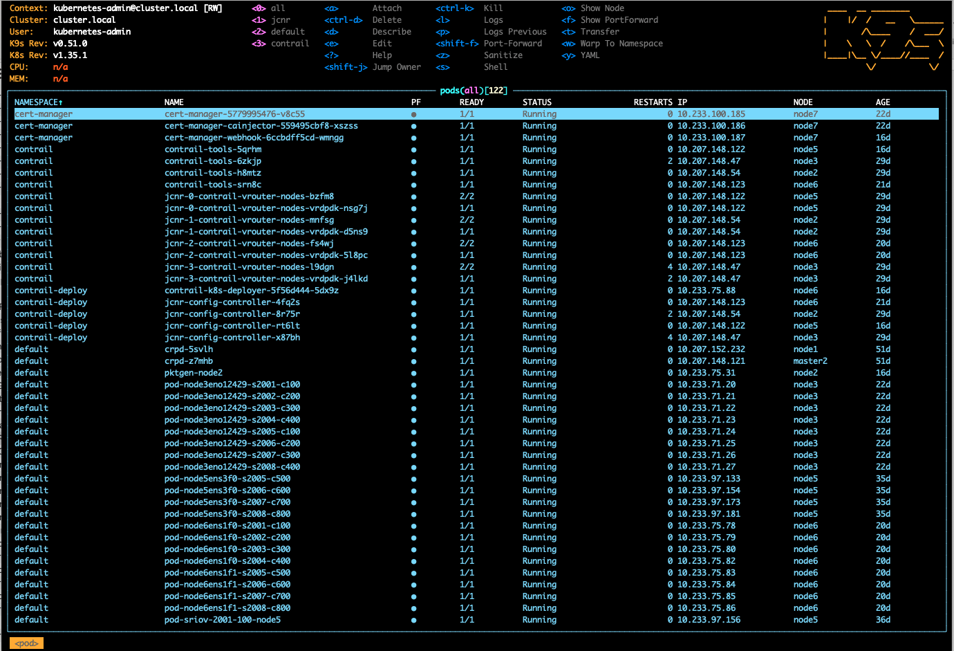
- Type ‘1’ on the screen to open ‘jcnr’ pods. On the highlighted pod type ‘s’ on screen to enter shell mode
Figure 30: View JCNR Pods
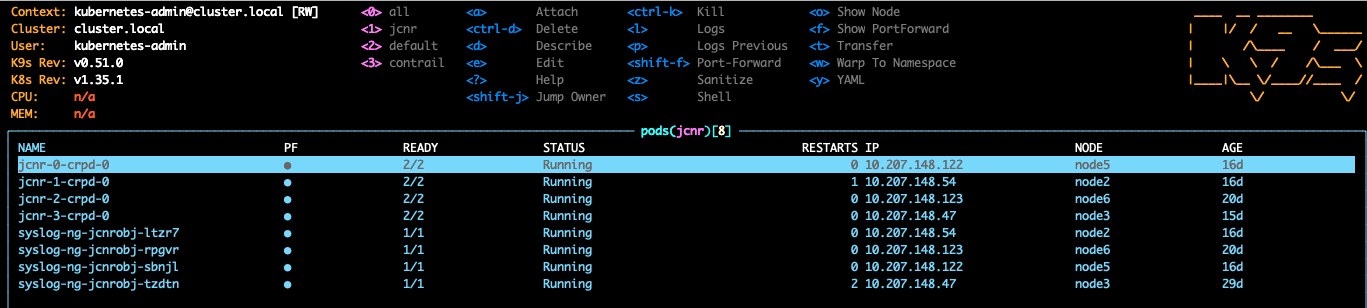
- On the highlighted pod press up and down keys to select the pod and type ‘s’ on screen to enter shell mode.
Figure 31: Shell Mode
Press enter on
crpdto open the container shell.Enter the ‘cli’ mode and apply the junos OS configuration on JCNR. Repeat this step for all JCNR pods. After applying the config if returning to the main screen type ‘Exit’ twice to return to K9s GUI and then press ‘ESC’ and type ‘0’ to return to the main POD screen.
root@node2:/# ls
bin   config  etc   junos  lib32  libx32  mfs  opt  proc  run   smid_client_sem    smt_bbeOsClientRegistrar  srv  tmp  var
boot  dev     home  lib    lib64  media   mnt  pkg  root  sbin  smid_client_shmem  sonic                     sys  usr
root@node2:/# cli
root@node2> show configuration
## Last commit: 2026-08-03 14:41:50 UTC by root
version 20250610.050931_builder.r1495969;
groups {
    base { /* OMITTED */ };
    cni { /* OMITTED */ };
    internal { /* OMITTED */ };
}
apply-groups [ base internal cni ];
interfaces {
    bond0 {
        description "Fabric Interface";
        mtu 9100;
        unit 0 {
            description "VLAN 4000"; <<< VLAN 4000 configured as VN on Apstra
            family inet {
                address 172.31.255.3/24;
            }
            family inet6 {
                address fd51:9b86:a688:2862::3/64;
            }
        }
    }
    lo0 {
        unit 0 {
            family inet {
                address 173.31.255.3/32;
            }
            family inet6 {
                address fd52:9b86:a688:2862::3/128;
            }
        }
    }
}
policy-options {
    policy-statement pplb {
        then {
            load-balance per-packet;
        }
    }
}
routing-options {
    route-distinguisher-id 172.31.255.3;
    rib inet6.0 {
        static {
            route fd86:08ff:73b0:22de::b/128 next-hop fd51:9b86:a688:2862::ffff;
            route fdf8:db3c:29c5:ac6c::ffff:ffff/128 next-hop fd51:9b86:a688:2862::ffff;
        }
    }
    router-id 173.31.255.3;
    autonomous-system 4200000002;
    dynamic-tunnels {
        jcnr-overlay {
            source-address fd52:9b86:a688:2862::3;
            udp;
            destination-networks {
                fd86:8ff:73b0:22de::b/128;
                fd52:9b86:a688:2862::/64;
            }
        }
    }
    forwarding-table {
        export pplb;
    }
}
protocols {
    bgp {
        group client {          <<< IBGP with vrr to gather routes from Offramp gateway
            type internal;
            local-address fd52:9b86:a688:2862::3;
            family inet-vpn {
                unicast {
                    extended-nexthop;
                }
            }
            family inet6-vpn {
                unicast;
            }
            local-as 4200000001;
            neighbor fd86:8ff:73b0:22de::b;
            vpn-apply-export;
        }
    }
    lldp {
        interface all;
    }
}- Enter the ‘cli’ mode and apply the junos OS configuration on JCNR. Repeat this step for all JCNR pods. After applying config to end the K9s GUI, type ‘Exit’ twice to return to K9s GUI and then press ‘ESC’ and type ‘0’ to return main POD screen.
Virtual Route Reflector Setup
For configuring vRR a dedicated juniper cRPD pod is deployed on both master nodes. Juniper cRPD is deployed to configure vRR so as to exchange the JCNR and offramp gateway routes.
For cRPD deployment follow the cRPD quick start guide to deploy Kubernetes containers.
root@node1:~# kubectl get pods -o wide
NAME                           READY   STATUS    RESTARTS   AGE   IP               NODE      NOMINATED NODE   READINESS GATES
crpd-5svlh                     1/1     Running   0          53d   10.207.152.232   master1     <none>           <none>
crpd-z7mhb                     1/1     Running   0          53d   10.207.148.121   master2   <none>           <none>
Run K9s command on the master node CLI and type the option from top that points to the default namespace for cRPD pod.
Figure 32: Select CRPD Pod
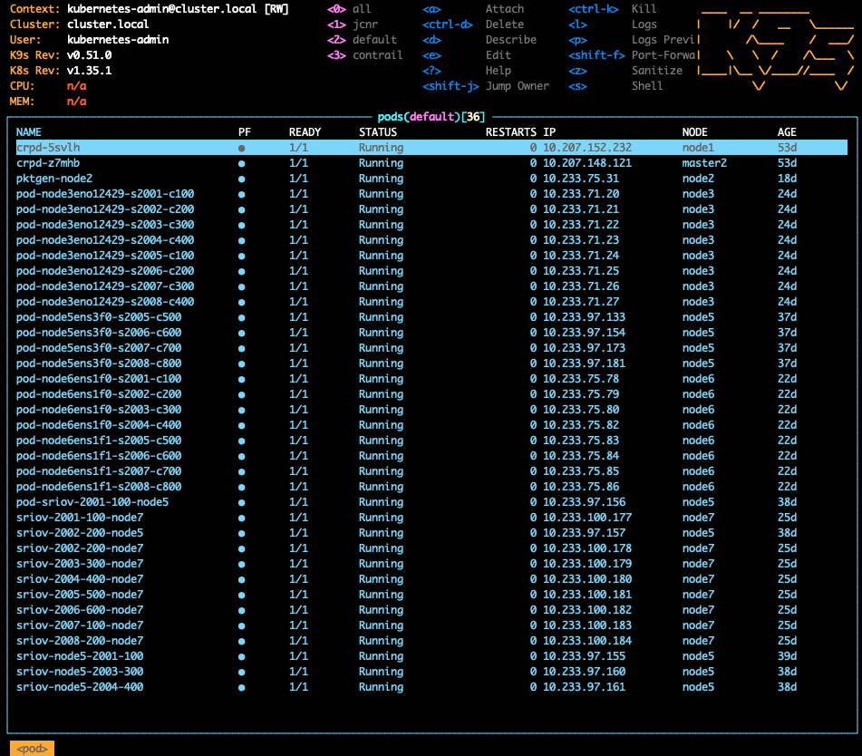
Select the cRPD Pod by moving the cursor Up and down and highlighting the pod and press Enter. On the next screen the container information is shown. Here type ‘s’ to get into the container shell mode. Type ‘cli’ and configure the vRR.
## Last commit: 2026-07-27 21:36:58 UTC by root
version 20251208.182209_builder.r1529419;
interfaces {
    eno12399.4010 {
        unit 0 {
            family inet {
                address 193.168.255.10/24;
            }
            family inet6 {
                address fdf8:db3c:29c5:ac6c::ffff:ffff/64;
            }
        }
    }
    lo0 {
        unit 0 {
            family inet {
                address 193.168.1.1/32;
            }
            family inet6 {
                address fdf9:db3c:29c5:ac6c::ffff:ffff/128;
            }
        }
    }
}
routing-options {
    rib inet6.0 {
        static {
            route fd52:9b86:a688:2862::3/128 next-hop fdf8:db3c:29c5:ac6c::ffff;
            route fd86:8ff:73b0:22de::b/128 next-hop fdf8:db3c:29c5:ac6c::ffff;
            route fdf8:db3c:29c5:ac6c::ffff:ffff/128 next-hop fd51:9b86:a688:2862::ffff;
        }
    }
    router-id 193.168.1.1;
    autonomous-system 4200000001;
    static {
        route 192.168.255.11/32 next-hop 193.168.255.1;
    }
}
protocols {
    bgp {
        group client {
            type internal;
            local-address fdf9:db3c:29c5:ac6c::ffff:ffff;
            family inet-vpn {
                unicast {
                    nexthop-resolution {
                        no-resolution;
                    }
                    extended-nexthop;
                }
            }
            family inet6-vpn {
                unicast {
                    nexthop-resolution {
                        no-resolution;
                    }
                }
            }
            cluster 193.168.1.1;
            neighbor fd86:8ff:73b0:22de::b;
            neighbor fd52:9b86:a688:2862::3;
        }
    }
    lldp {
        interface all;
    }
}
SR-IOV: Overlay Network-Based Q-in-Q Configuration on SR-IOV
- For SR-IOV workloads before deploying SR-IOV workload ensure
nmstateis deployed.Nmstateto perform state driven network configuration on cluster nodes and to report back their current state. Both the configuration and reporting are controlled through Kubernetes objects.
((.venv) ) root@master1:~/kubespray# git clone https://github.com/nmstate/Kubernetes-nmstate.git
((.venv) ) root@master1:~/kubespray# cd Kubernetes-nmstate/deploy
((.venv) ) root@master1:~/kubespray/Kubernetes-nmstate/deploy# kubectl apply -f crds/nmstate.io_nodenetworkconfigurationpolicies.yaml
kubectl apply -f crds/nmstate.io_nodenetworkstates.yaml
customresourcedefinition.apiextensions.k8s.io/nodenetworkconfigurationpolicies.nmstate.io created
customresourcedefinition.apiextensions.k8s.io/nodenetworkstates.nmstate.io created
((.venv) ) root@master1:~/kubespray/Kubernetes-nmstate/deploy# kubectl get crds | grep nmstate
nodenetworkconfigurationpolicies.nmstate.io             2026-06-24T12:28:40Z
nodenetworkstates.nmstate.io                            2026-06-24T12:28:40Z
((.venv) ) root@master1:~/kubespray/Kubernetes-nmstate/deploy# kubectl apply -f operator.yaml- Create Virtual Functions (VFs) and expose them to SR-IOV Operator. The node’s NIC creates Virtual Functions (VFs). These VFs act as lightweight virtual NICs carved out of the physical NIC. Apply each of the nmstate-vfs.yaml file using command
kubectl apply -fwith filename. For instance,kubectl apply -f nmstate-master1-vfs.yaml
root@master1:~# cd kubespray/SR-IOV/
root@master1:~/kubespray/SR-IOV# cat nmstate-master1-vfs.yaml
apiVersion: nmstate.io/v1
kind: NodeNetworkConfigurationPolicy
metadata:
  name: sriov-master1-intel
spec:
  nodeSelector:
    Kubernetes.io/hostname: master1
  desiredState:
    interfaces:
      - name: eno12409
        description: Intel E710 SR-IOV Port (Master1)
        type: ethernet
        state: up
        mtu: 9000
        ipv4:
          enabled: false
        ipv6:
          enabled: false
        ethernet:
          sr-iov:
            total-vfs: 4

root@master1:~/kubespray/SR-IOV# cat nmstate-node2-vfs.yaml
apiVersion: nmstate.io/v1
kind: NodeNetworkConfigurationPolicy
metadata:
  name: sriov-node2-intel
spec:
  nodeSelector:
    Kubernetes.io/hostname: node2
  desiredState:
    interfaces:
      - name: ens3f0
        description: Intel E810 SR-IOV Port (Node2)
        type: ethernet
        state: up
        mtu: 9000
        ipv4:
          enabled: false
        ipv6:
          enabled: false
        ethernet:
          sr-iov:
            total-vfs: 4

root@master1:~/kubespray/SR-IOV# cat nmstate-node3-vfs.yaml
apiVersion: nmstate.io/v1
kind: NodeNetworkConfigurationPolicy
metadata:
  name: sriov-node5-intel
spec:
  nodeSelector:
    Kubernetes.io/hostname: node5
  desiredState:
    interfaces:
      - name: eno12399
        description: Intel E810 SR-IOV Port (Node5)
        type: ethernet
        state: up
        mtu: 9000
        ipv4:
          enabled: false
        ipv6:
          enabled: false
        ethernet:
          sr-iov:
            total-vfs: 16

root@master1:~/kubespray/SR-IOV# cat nmstate-node5-vfs.yaml
apiVersion: nmstate.io/v1
kind: NodeNetworkConfigurationPolicy
metadata:
  name: sriov-node3-intel
spec:
  nodeSelector:
    Kubernetes.io/hostname: node3
  desiredState:
    interfaces:
      - name: eno12399
        description: Intel E810 SR-IOV Port (Node3)
        type: ethernet
        state: up
        mtu: 9000
        ipv4:
          enabled: false
        ipv6:
          enabled: false
        ethernet:
          sr-iov:
            total-vfs: 4

root@master1:~/kubespray/SR-IOV# cat nmstate-node6-vfs.yaml
apiVersion: nmstate.io/v1
kind: NodeNetworkConfigurationPolicy
metadata:
  name: sriov-node6-intel
spec:
  nodeSelector:
    Kubernetes.io/hostname: node6
  desiredState:
    interfaces:
      - name: ens1f0np0
        description: Intel E810 SR-IOV Port 0 (Node6)
        type: ethernet
        state: up
        mtu: 9000
        ipv4:
          enabled: false
        ipv6:
          enabled: false
        ethernet:
          sr-iov:
            total-vfs: 64
      - name: ens1f1np1
        description: Intel E810 SR-IOV Port 1 (Node6)
        type: ethernet
        state: up
        mtu: 9000
        ipv4:
          enabled: false
        ipv6:
          enabled: false
        ethernet:
          sr-iov:
total-vfs: 64- Make sure that the Virtual Functions created above are available for the Kubernetes scheduler. Create files targeting hardware vendor ID and device code as shown in the following for each node. The custom resource name label
resourceNameexposes the Virtual Functions to the Kubernetes for scheduling inside pods.nodeSelectortells Kubernetes which node the resource is available. Push the policy usingkubectl apply -fcommand for each policy file.
root@master1:~/kubespray/SR-IOV# cat sriovnetpolicy-node-network.yaml

---
apiVersion: sriovnetwork.openshift.io/v1
kind: SriovNetworkNodePolicy
metadata:
  name: sriov-node3-x710
  namespace: sriov-network-operator
spec:
  resourceName: resourceX710
  nodeSelector:
    Kubernetes.io/hostname: node3
  priority: 10
  numVfs: 4
  externallyManaged: false
  deviceType: netdevice
  isRdma: false
  nicSelector:
    vendor: "8086"
    deviceID: "1572"
    rootDevices:
      - "0000:32:00.0"
    pfNames:
      - "eno12399#0-3"
---
apiVersion: sriovnetwork.openshift.io/v1
kind: SriovNetworkNodePolicy
metadata:
  name: sriov-node2-x810
  namespace: sriov-network-operator
spec:
  resourceName: resourceX810
  nodeSelector:
    Kubernetes.io/hostname: node2
  priority: 10
  numVfs: 4
  externallyManaged: false
  deviceType: netdevice
  isRdma: false
  nicSelector:
    vendor: "8086"
    deviceID: "159b"
    rootDevices:
      - "0000:9f:00.0"
    pfNames:
      - "ens3f0#0-3"

root@master1:~/kubespray/SR-IOV# cat sriovnetpolicy-node5-network.yaml

---
apiVersion: sriovnetwork.openshift.io/v1
kind: SriovNetworkNodePolicy
metadata:
  name: sriov-node5-x810
  namespace: sriov-network-operator
spec:
  resourceName: resourceC810
  nodeSelector:
    Kubernetes.io/hostname: node5
  priority: 10
  numVfs: 16
  externallyManaged: false
  deviceType: netdevice
  isRdma: false
  nicSelector:
    vendor: "8086"
    deviceID: "1592"
    rootDevices:
      - "0000:12:00.0"
    pfNames:
      - "ens1f0np0#0-15"
root@master1:~/kubespray/SR-IOV# cat sriovnetpolicy-node6-network.yaml

---
apiVersion: sriovnetwork.openshift.io/v1
kind: SriovNetworkNodePolicy
metadata:
  name: sriov-node6-c810-port0
  namespace: sriov-network-operator
spec:
  resourceName: resourceC810port0
  nodeSelector:
    Kubernetes.io/hostname: node6
  priority: 10
  numVfs: 64
  externallyManaged: false
  deviceType: netdevice
  isRdma: false
  nicSelector:
    vendor: "8086"
    deviceID: "1592"
    rootDevices:
      - "0000:12:00.0"
    pfNames:
      - "ens1f0np0#0-63"

---
apiVersion: sriovnetwork.openshift.io/v1
kind: SriovNetworkNodePolicy
metadata:
  name: sriov-node6-c810-port1
  namespace: sriov-network-operator
spec:
  resourceName: resourceC810port1
  nodeSelector:
    Kubernetes.io/hostname: node6
  priority: 10
  numVfs: 64
  externallyManaged: false
  deviceType: netdevice
  isRdma: false
  nicSelector:
    vendor: "8086"
    deviceID: "1592"
    rootDevices:
      - "0000:12:00.1"
    pfNames:
      - "ens1f1np1#0-63"
Set up outer SR-IOV tenant VLAN overlays (Service VLANs). Apply the configuration using commands:
kubectl apply -f nad-sriov-t1-svlan.yamlkubectl apply -f nad-sriov-t2-svlan.yaml
root@master1:~/kubespray/SR-IOV# ls | grep svlan
nad-sriov-t1-svlan.yaml
nad-sriov-t2-svlan.yaml
root@master1:~/kubespray/SR-IOV# cat nad-sriov-t1-svlan.yaml
apiVersion: sriovnetwork.openshift.io/v1
kind: SriovNetwork
metadata:
  name: sriovnetwork-1q-t1-svlan
  namespace: sriov-network-operator
spec:
  ipam: |-
    {}
  vlan: 2001
  spoofChk: "off"
  trust: "off"
  vlanProto: "802.1q"
  linkState: "auto"
  capabilities: '{ "mac": true }'
  networkNamespace: default
  resourceName: resourceX710

---
apiVersion: sriovnetwork.openshift.io/v1
kind: SriovNetwork
metadata:
  name: sriovnetwork-1q-t1-svlan-x810
  namespace: sriov-network-operator
spec:
  ipam: "{}"
  vlan: 2001
  spoofChk: "off"
  trust: "off"
  vlanProto: "802.1q"
  linkState: "auto"
  capabilities: '{ "mac": true }'
  networkNamespace: default
  resourceName: resourceX810   # node2 PF
root@master1:~/kubespray/SR-IOV# cat nad-sriov-t2-svlan.yaml
apiVersion: sriovnetwork.openshift.io/v1
kind: SriovNetwork
metadata:
  name: sriovnetwork-1q-t2-svlan
  namespace: sriov-network-operator
spec:
  ipam: |-
    {}
  vlan: 2002
  spoofChk: "off"
  trust: "off"
  vlanProto: "802.1q"
  linkState: "auto"
  capabilities: '{ "mac": true }'
  networkNamespace: default
  resourceName: resourceX710

---
apiVersion: sriovnetwork.openshift.io/v1
kind: SriovNetwork
metadata:
  name: sriovnetwork-1q-t2-svlan-x810
  namespace: sriov-network-operator
spec:
  ipam: "{}"
  vlan: 2002
  spoofChk: "off"
  trust: "off"
  vlanProto: "802.1q"
  linkState: "auto"
  capabilities: '{ "mac": true }'
  networkNamespace: default
resourceName: resourceX810 # node2 PF- Create the inner customer VLAN (C-VLAN) for each tenant. The file Includes IPAM configuration (IP assignment) and routing rules for pod interfaces. Apply the configuration using commands:
kubectl apply -fnad-sriov-t1-vn1-cvlan.yaml
kubectl apply -fnad-sriov-t1-vn2-cvlan.yaml
kubectl apply -fnad-sriov-t2-vn1-cvlan.yaml
root@master1:~/kubespray/SR-IOV# cat nad-sriov-t1-vn1-cvlan.yaml
apiVersion: k8s.cni.cncf.io/v1
kind: NetworkAttachmentDefinition
metadata:
  name: nad-sriov-t1-vn1
  namespace: default
spec:
  config: '{
      "name": "nad-sriov-t1-vn1",
      "cniVersion": "0.3.1",
      "type": "vlan",
      "linkInContainer": true,
      "master": "net1",
      "vlanId": 100,
      "ipam": {
        "type": "whereabouts",
        "ipRanges": [{
          "range": "10.201.255.0/24",
          "exclude": [
            "10.201.255.1/32",
            "10.201.255.2/32",
            "10.201.255.254/32"
          ]
        }, {
          "range": "2001::10:201:255:0/112",
          "exclude": [
            "2001::10:201:255:1/128",
            "2001::10:201:255:2/128",
            "2001::10:201:255:ffff/128"
          ]
        }],
        "routes": [
          { "dst": "10.211.255.0/24", "gw": "10.201.255.254" },
          { "dst": "10.202.255.0/24", "gw": "10.201.255.254" },
          { "dst": "2001::10:211:255:0/112", "gw": "2001::10:201:255:ffff" },
          { "dst": "2001::10:202:255:0/112", "gw": "2001::10:201:255:ffff" }
        ]
      }
    }'

root@master1:~/kubespray/SR-IOV# cat nad-sriov-t1-vn2-cvlan.yaml
apiVersion: k8s.cni.cncf.io/v1
kind: NetworkAttachmentDefinition
metadata:
  name: nad-sriov-t1-vn2
  namespace: default
spec:
  config: '{
      "name": "nad-sriov-t1-vn2",
      "cniVersion": "0.3.1",
      "type": "vlan",
      "linkInContainer": true,
      "master": "net1",
      "vlanId": 200,
      "ipam": {
        "type": "whereabouts",
        "ipRanges": [{
          "range": "10.202.255.0/24",
          "exclude": [
            "10.202.255.1/32",
            "10.202.255.2/32",
            "10.202.255.254/32"
          ]
        }, {
          "range": "2001::10:202:255:0/112",
          "exclude": [
            "2001::10:202:255:1/128",
            "2001::10:202:255:2/128",
            "2001::10:202:255:ffff/128"
          ]
        }],
        "routes": [
          { "dst": "10.211.255.0/24", "gw": "10.202.255.254" },
          { "dst": "10.201.255.0/24", "gw": "10.202.255.254" },
          { "dst": "2001::10:211:255:0/112", "gw": "2001::10:202:255:ffff" },
          { "dst": "2001::10:201:255:0/112", "gw": "2001::10:202:255:ffff" }
        ]
      }
    }'

root@master1:~/kubespray/SR-IOV# cat nad-sriov-t2-vn1-cvlan.yaml
apiVersion: k8s.cni.cncf.io/v1
kind: NetworkAttachmentDefinition
metadata:
  name: nad-sriov-t2-vn1
  namespace: default
spec:
  config: '{
      "name": "nad-sriov-t2-vn1",
      "cniVersion": "0.3.1",
      "type": "vlan",
      "linkInContainer": true,
      "master": "net1",
      "vlanId": 100,
      "ipam": {
        "type": "whereabouts",
        "ipRanges": [{
          "range": "10.211.255.0/24",
          "exclude": [
            "10.211.255.1/32",
            "10.211.255.2/32",
            "10.211.255.254/32"
          ]
        }, {
          "range": "2001::10:211:255:0/112",
          "exclude": [
            "2001::10:211:255:1/128",
            "2001::10:211:255:2/128",
            "2001::10:211:255:ffff/128"
          ]
        }],
        "routes": [
          { "dst": "10.201.255.0/24", "gw": "10.211.255.254" },
          { "dst": "10.202.255.0/24", "gw": "10.211.255.254" },
          { "dst": "2001::10:201:255:0/112", "gw": "2001::10:211:255:ffff" },
          { "dst": "2001::10:202:255:0/112", "gw": "2001::10:211:255:ffff" }
        ]
      }
}'- Connect the Application pods to the Virtual Functions by creating pod files and applying it. Each pod attaches to its VF-based interface (net1) with VLAN overlays, IP addresses, and routes applied. Add the Multus networking annotation to the Pod metadata segment:
k8s.v1.cni.cncf.io/networks.
kubectl apply -f pod-sriov-t1-vn1-c0.yaml
kubectl apply -f pod-sriov-t1-vn1-c2.yaml
kubectl apply -f pod-sriov-t1-vn2-c2.yaml
kubectl apply -f pod-sriov-t2-vn1-c0.yaml
root@master1:~/kubespray/SR-IOV# cat pod-sriov-t1-vn1-c0.yaml
apiVersion: v1
kind: Pod
metadata:
  name: net-tools-sriov-t1-vn1-c0
  annotations:
    k8s.v1.cni.cncf.io/networks: sriovnetwork-1q-t1-svlan-x810, nad-sriov-t1-vn1
spec:
  containers:
    - name: net-tools
      image: rtsp/net-tools:latest
      imagePullPolicy: IfNotPresent
      securityContext:
        privileged: true
      resources:
        requests:
          openshift.io/resourceX810: "1"
        limits:
          openshift.io/resourceX810: "1"
  nodeSelector:
    Kubernetes.io/hostname: node2
root@master1:~/kubespray/SR-IOV# pod-sriov-t1-vn1-c2.yaml
pod-sriov-t1-vn1-c2.yaml: command not found
root@master1:~/kubespray/SR-IOV# cat pod-sriov-t1-vn1-c2.yaml
apiVersion: v1
kind: Pod
metadata:
  name: net-tools-sriov-t1-vn1-c2
  annotations:
    k8s.v1.cni.cncf.io/networks: sriovnetwork-1q-t1-svlan, nad-sriov-t1-vn1
spec:
  containers:
    - name: net-tools
      image: rtsp/net-tools:latest
      imagePullPolicy: IfNotPresent
      securityContext:
        privileged: true
      resources:
        requests:
          openshift.io/resourceX710: "1"
        limits:
          openshift.io/resourceX710: "1"
  nodeSelector:
    Kubernetes.io/hostname: node3