Configuration Walkthrough
This walkthrough summarizes the steps required to configure the Collapsed Data Center Fabric with Juniper Apstra JVD. For more detailed step-by-step configuration information, see Juniper Apstra User Guide . Notes provide additional guidance in this walkthrough.
This walkthrough details the configuration of the baseline design, as used during validation in the Juniper data center validation test lab. The baseline design consists of two QFX5120-48Y switches in the collapsed spine role. The goal of JVD is to provide options so that the baseline switch platform can be replaced with any validated switch platform for that role, as described in the Juniper Hardware Components section. To keep this walkthrough a manageable length, only the baseline design platform is used for the purposes of this document.
Apstra: Configure Apstra Server and Add Switches
This document does not cover the installation of Apstra. For more information about installation, see Juniper Apstra User Guide .
The first step is to configure the Apstra Server. Upon connecting to the Apstra Server VM for the first time, a configuration wizard launches. Here, passwords for the Apstra server, Apstra UI, and network configuration can be configured.
Apstra: Management of Junos OS Device
There are two methods of adding Juniper devices into Apstra: manually or in bulk using ZTP:
To add devices manually (recommended):
- In the Apstra UI, navigate to Devices > Agents > Create Offbox Agents. This requires the devices to be configured with a minimum of the root password and management IP.
To add devices through ZTP:
- To add devices from the Apstra ZTP server and more information on the ZTP of Juniper devices, see Juniper Apstra User Guide .
For the purposes of this setup, a root password and management IPs were already configured on all switches prior to adding the devices to Apstra. To add switches to Apstra, first log on to Apstra Web UI, choose a method of device addition as per above and provide the appropriate username and password that is preconfigured for those devices.
Apstra pulls the configuration from Juniper devices called pristine config. The Junos OS configuration ‘groups’ stanza is ignored when importing the pristine configuration, and Apstra will not validate any group configuration listed in the inheritance model, see Use Configuration Groups to Quickly Configure Devices . However, it’s best practice to avoid setting loopbacks, interfaces (except management interface), routing-instances (except management-instance). Apstra will set the protocols LLDP and RSTP when device is successfully Acknowledged.
Create Agent Profile
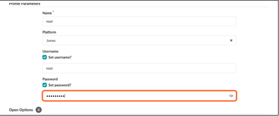
For the purposes of this JVD lab, the root user and password are the same across all devices; hence, an agent profile is created, as shown below; note that this also obscures the password, which keeps it secure.
- Navigate to Devices > Agent Profiles.
- Click Create Agent Profile.
- Create an agent profile named root with the platform set to Junos.
- Add the username and password used to log into your switches.
Figure 2: Create Agent Profile in Apstra
Create Offbox Agent
An IP address range can be provided to bulk-add devices into Apstra.
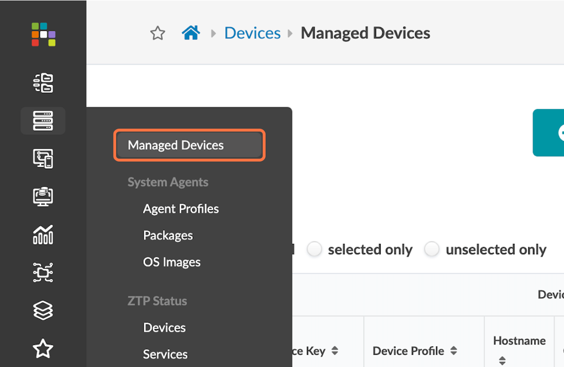
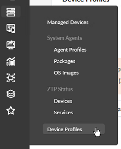
- Navigate to Devices > Managed Devices.
- Click on Create Offbox Agents.
Figure 3: Devices Menu, with Managed Devices Highlighted
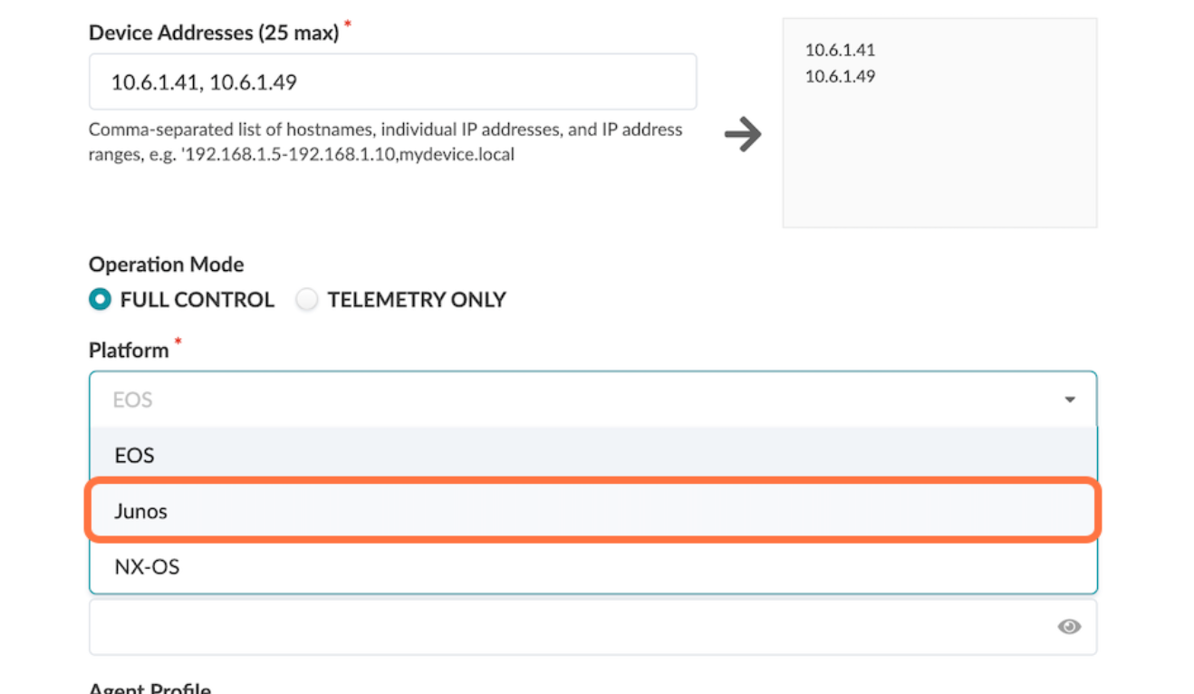
- Add the management addresses of the switches, separated by a comma, in the Create Offbox Agents pop-up. You might enter an IP range instead if you prefer.
- Select Junos as the platform and full
control as the operation mode.
Figure 4: Create Offbox Agents Pop-up with the Platform Option Selecting Junos
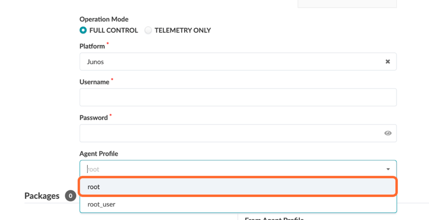
- Select the agent profile root created in the
previous step.
Figure 5: Create Offbox Agents Pop-up with the Agent Profile Option Selecting Root
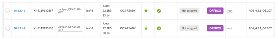
- Press Create and wait for the systems to populate in the Managed Devices table.
Figure 6: Managed Devices Table Showing the Entries Created After Cicking Create in the Previous Step
Add Pristine Configuration
Click on each of the newly created systems in the Devices > Managed Devices table, and then add the pristine configuration by collecting from the device or pushing from Apstra. The configuration applied as part of the pristine configuration should be the base configuration or minimal configuration required to reach the devices with the addition of any users, static routes to the management switch, and so on. This creates a backup of the base configuration in Apstra and allows devices to be reverted to the pristine configuration in case of any issues.
Figure 7: Add Pristine Config
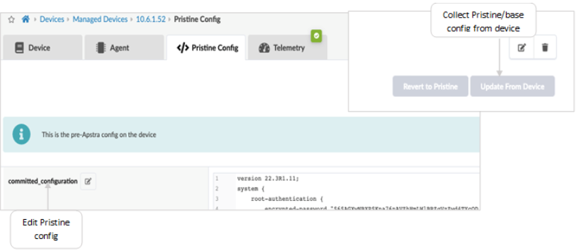
If the pristine configuration is updated using Apstra as shown in the above figure, then run Revert to Pristine.
Upgrade Junos OS
If your switches are not running the operating system release recommended by this JVD, you should upgrade them to the recommended version. For the purposes of this JVD, the recommended Junos OS version is 23.4R2-S3.
Important: A maintenance window is required to perform any device upgrade, as upgrades can be disruptive.Best practice recommendations for upgrade: Upgrade devices using the Junos OS CLI as outlined in the Junos OS Software Installation and Upgrade Guide , along with the Junos OS version release notes, as Apstra currently only performs basic upgrade checks. However, this JVD summarizes the steps to upgrade if Apstra is intended to be used for upgrades.If a device is added to the blueprint, set it to undeploy, unassign its serial number from the blueprint, and commit the changes, which reverts it back to Pristine Config. Then, proceed to upgrade. Once the upgrade is complete, add the device back to the blueprint.
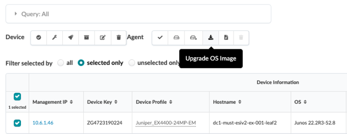
Apstra allows devices upgrade. However, the current best practice recommendation is to upgrade devices using the Junos OS CLI as outlined in the Junos OS Software Installation and Upgrade Guide , along with the Junos OS version release notes. This is because Apstra currently only performs basic upgrade checks. If you want to upgrade the device within Apstra, here is how you do it:
Figure 8: Upgrade Device from Apstra
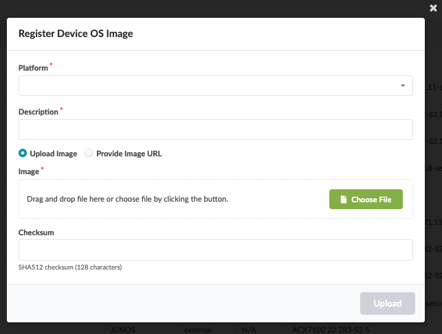
To register a Junos OS image on Apstra, either provide a link to the repository where all OS images are stored or upload the OS image as shown below. In the Apstra UI, navigate to Devices > OS Images and click Register OS Image.
Figure 9: Upload OS Image
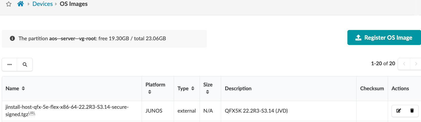
Figure 10: Register OS Image by Uploading or Provide Image URL
Fabric Provisioning
- Navigate to Devices > Managed Devices.
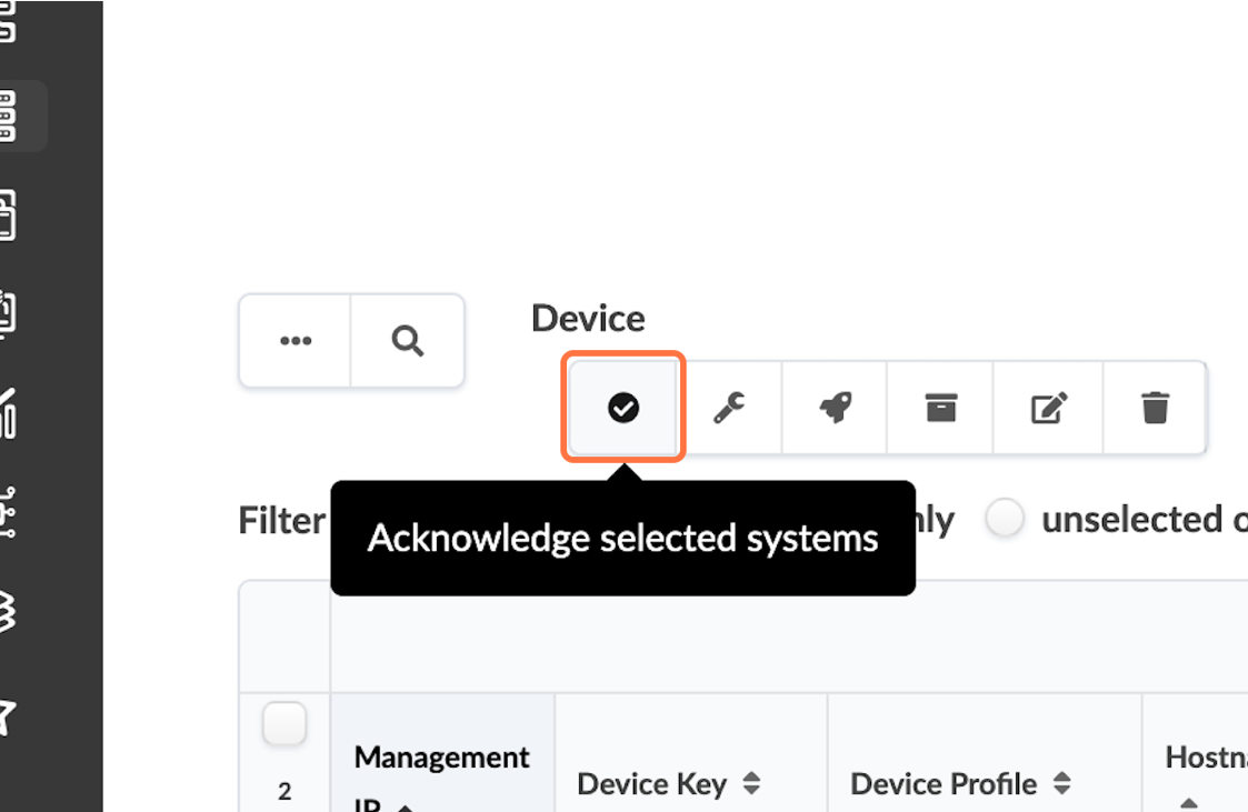
- Check Discovered Devices and Acknowledge the Devices.
- Click the checkbox interface to select all the devices once the offbox agent is added and the device information is collected.
- Click Acknowledge.
This places the switch under the management of the Apstra server.
Figure 11: Managed Devices Table Control Panel with the Acknowledge Selected Systems Highlighted
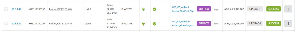
- Once a switch is acknowledged, the status icon under the Acknowledged? table header changes from a red no entry symbol to a green checkmark. Verify this change for all switches. If there are no changes, repeat the procedure to acknowledge the switches again.
Figure 12: Managed Devices Table Showing the Switches Successfully Under Apstra Management
After a device is managed by Apstra, all device configuration changes should be performed using Apstra. Do not perform configuration changes on devices outside of Apstra, as Apstra might revert those changes.
Once the devices are successfully acknowledged, perform the collect pristine config step detailed above once again, as Apstra adds LLDP and RSTP protocols to the switch configurations.
Identify and Create Logical Devices, Interface Maps with Device Profiles
Note: The device profiles covered in this JVD document are not modular chassis-based. For modular chassis-based devices such as QFX5700 the linecard profiles, chassis profile are available in Apstra and linked to the device profile. These cannot be edited; however, they can be cloned, and custom profiles can be created for linecard, chassis and device profile as shown below in Figure 11 and Figure 12.
The following steps define the Collapsed Data Center Fabric with Juniper Apstra JVD baseline architecture and devices. Before provisioning a blueprint, a replica of the topology is created. We define the ERB data center reference architecture and devices in the following steps.
This involves selecting logical devices for the collapsed spine switches. Logical devices are abstractions of physical devices that specify common device form factors such as the amount, speed, and roles of ports. Vendor-specific information is not included, which permits building the network definition before selecting vendors and hardware device models. The Apstra software installation includes many predefined logical devices that can be used to create any variation of the logical device.
- Logical devices are then mapped to device profiles using interface maps. The ports mapped to the interface maps match the device profile and physical connections. Again, the Apstra software installation includes many predefined interface maps and device profiles.
- Finally, the racks and templates are defined using the configured logical devices and device profiles, which are then used to create a blueprint.
The Juniper Apstra User Guide explains the device lifecycle, which must be understood when working with Apstra blueprints and devices.
Create Device Profile
For all devices covered in this document, the device profiles (defined in Apstra and found under Devices > Device Profiles) were exactly matched by Apstra when adding devices into Apstra, as covered in Apstra: Management of Junos OS Device . During the validation of supported devices, there are instances where device profiles had to be custom-made to suit the linecard setup on the device, for instance, QFX5700. For more information on device profiles, see Apstra User Guide for Device Profiles .
- Navigate to Devices > Device Profiles, then review the devices listed based on the number and speed of ports.
- Select the device that most closely resembles the switch for
which you want to create a device profile.
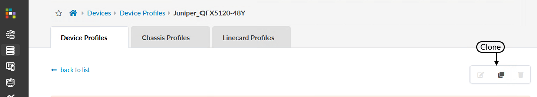
Figure 12: Devices Menu with the Device Profiles Button Highlighted
- Press the Clone button once you are confident
that the device profile you selected most closely resembles your
switch.
Figure 13: Device Profile Page with the Clone Button Pointed Out
 Note:
Note:System already added, or default logical devices cannot be changed.
- Name the cloned profile that you will use for this blueprint.
Figure 14: Clone Device Profile Pop-Up
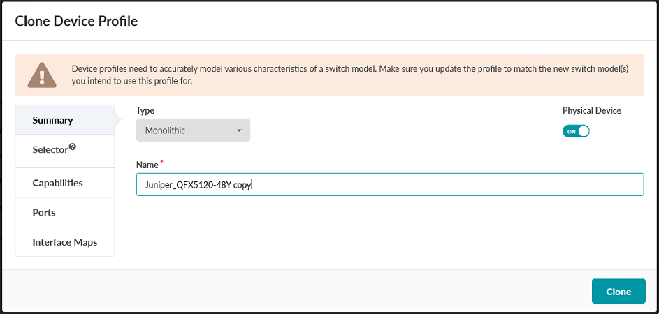
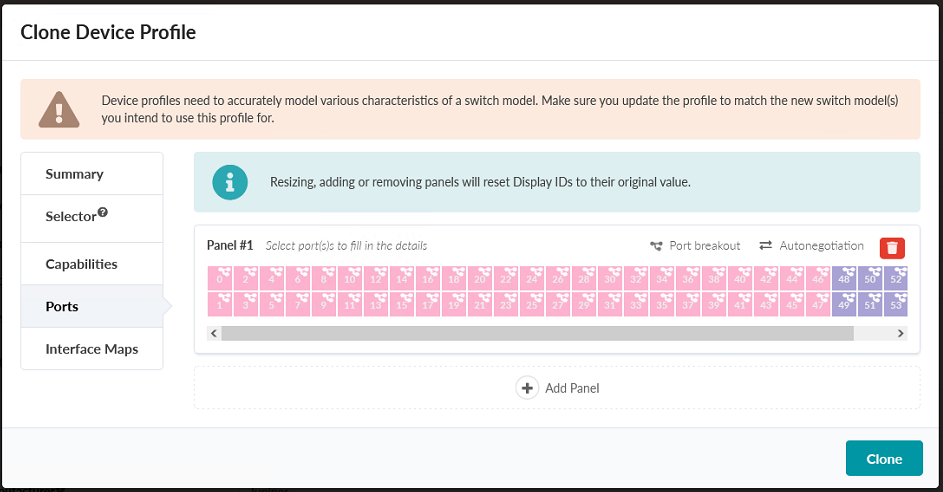
- Click Ports to verify that the port selection matches your device. If it does not, modify the port layout, then press Clone.
Figure 14: Clone Device Profile Pop-up
Create Logical Device
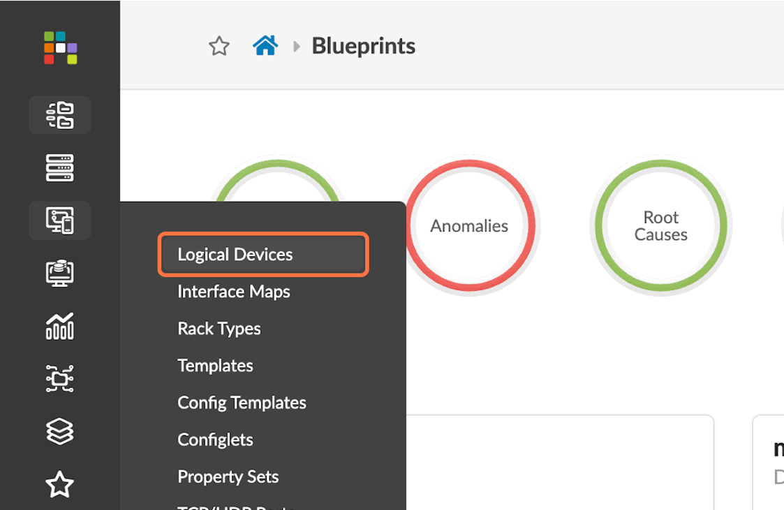
- Navigate to Design > Logical Devices and
then select the Create Logical Device button in
the upper-right corner.
Figure 15: Design Menu with the Logical Device Button Highlighted
- Create a logical device with the name
JVD_QFX5120-48-y-8c.
Figure 16: The Create Logical Device Page
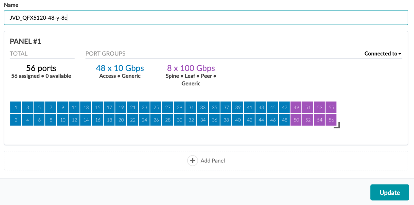
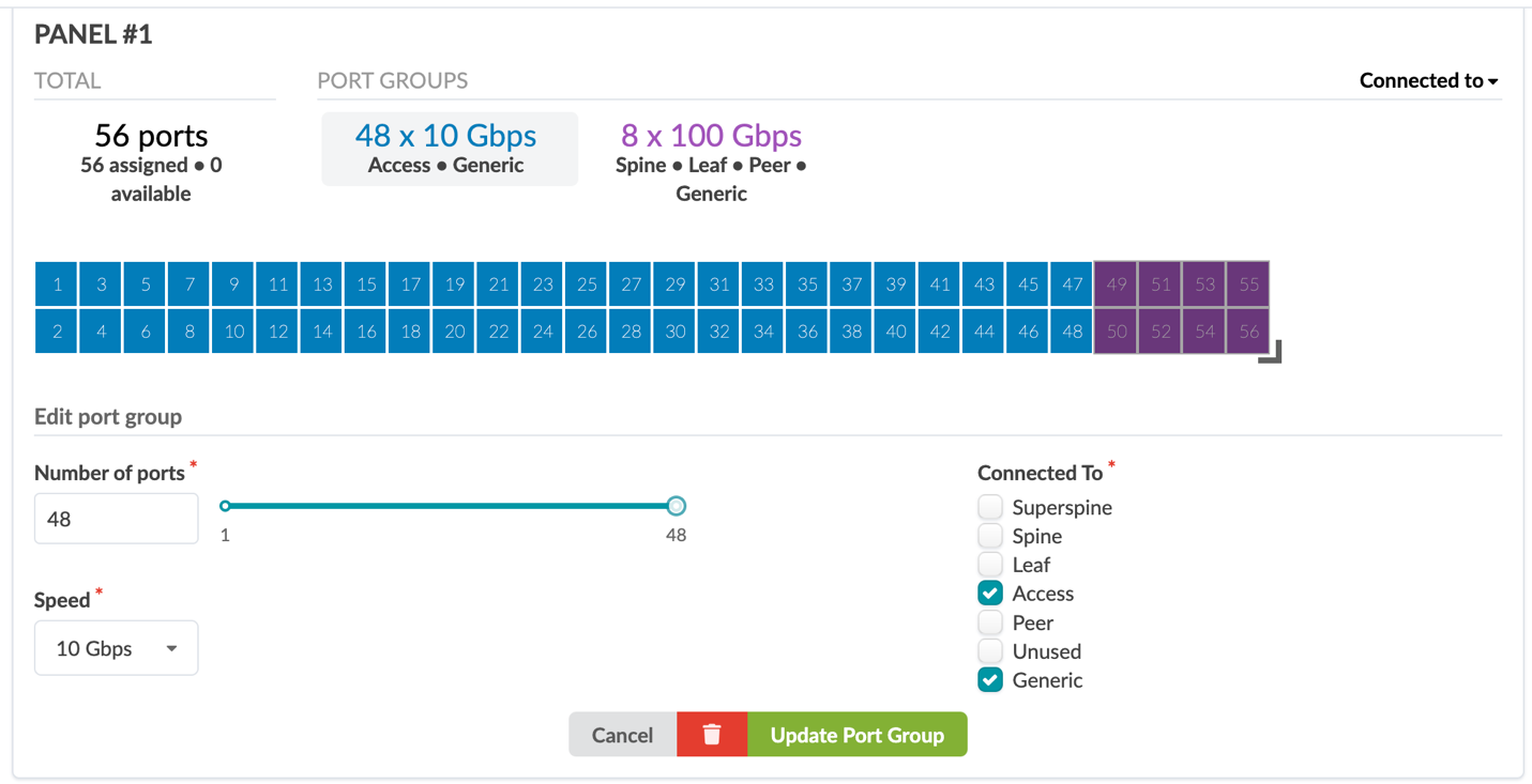
Figure 17: Create Logical Devices Page with the Access Ports Highlighted 48 10 Gbps Ports Assigned for Access and Generic Devices
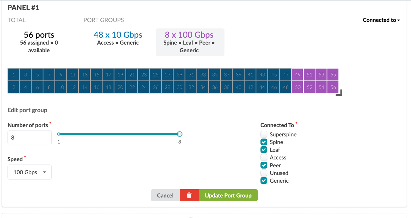
- Assign eight 100 Gbps ports for spine, leaf, peer, and generic connections.
Figure 18: Create Logical Devices Page with the Uplink Ports Highlighted
Create Interface Map
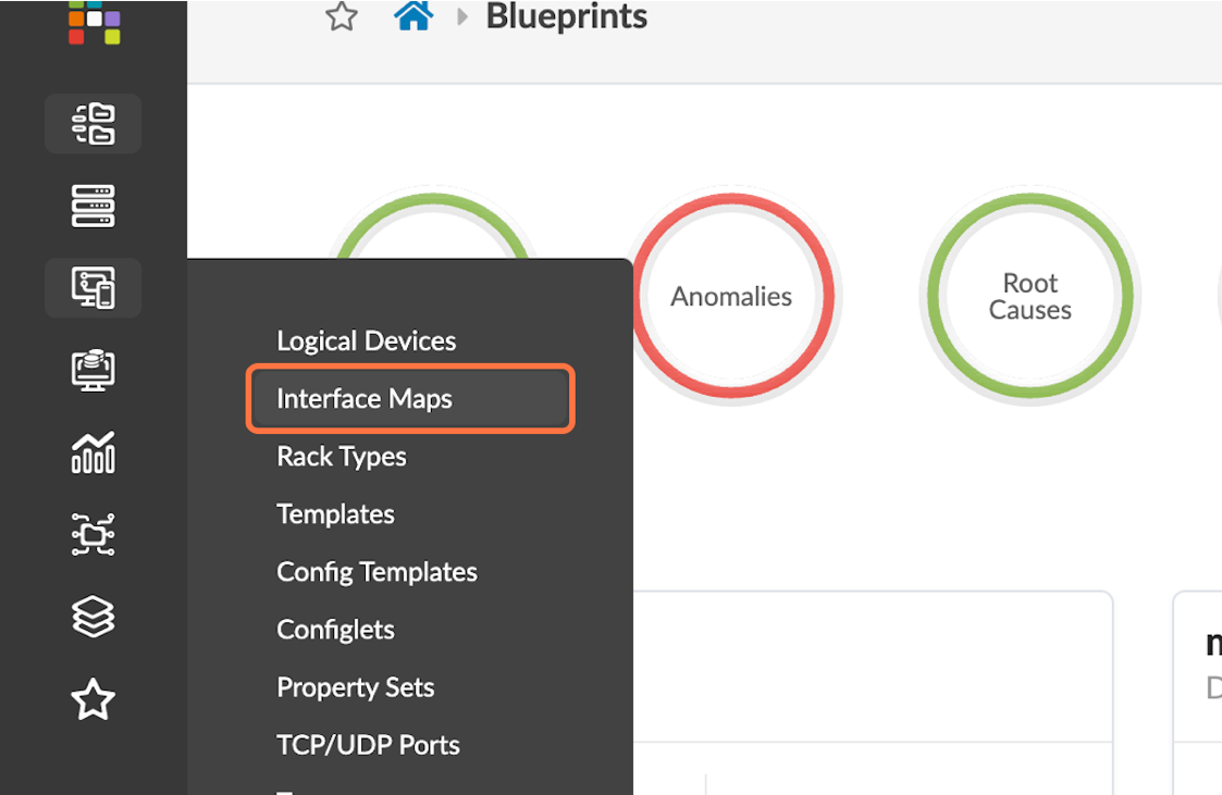
- Navigate to Design > Logical Devices and
then select the Create Interface Map button in the
upper-right corner.
Figure 19: Design Menus with the Interface Maps Button Highlighted
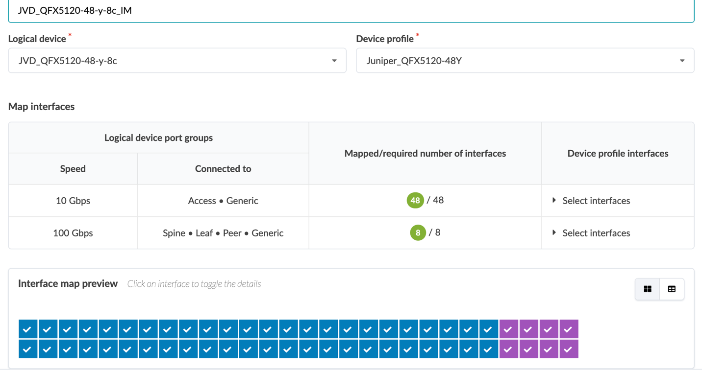
- Name the interface map JVD_QFX5120-48y-8c_IM.
- Select the logical device and device profile created earlier.
- Click Select with all interfaces assigned interfaces text in the Device profile interfaces column, and then assign all 48x10 Gbps ports and 8x100 Gbps ports as appropriate.
Figure 20: Create Interface Map Pop-up Showing the Interface Map Preview
Create Rack Type
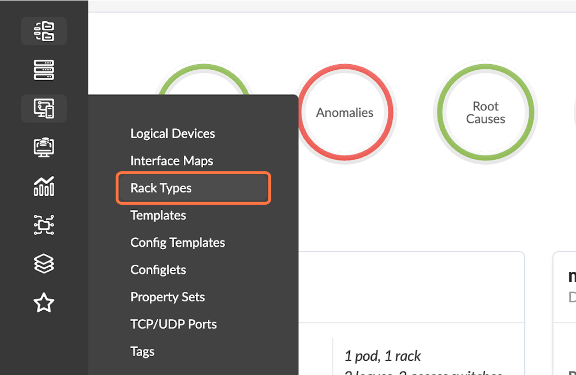
- Navigate to Design > Rack Types.
Figure 21: Design Menu with the Rack Types Button Highlighted
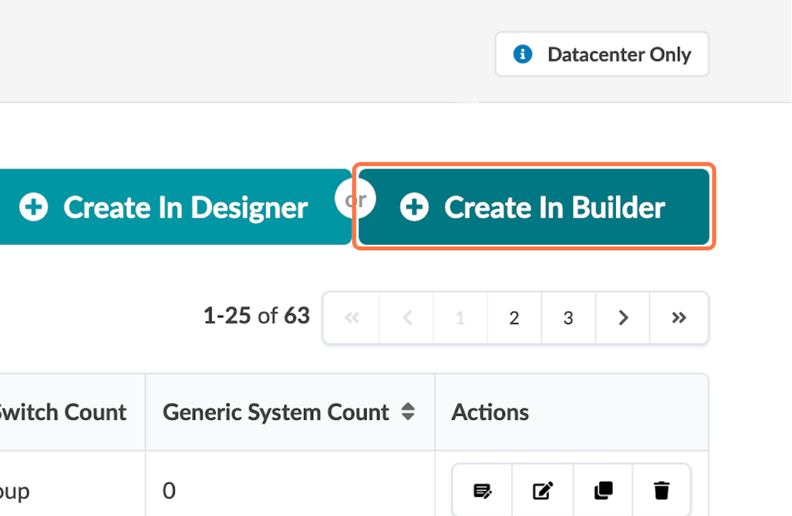
- Select Create In Builder in the upper-right
corner.
Figure 22: The Rack Types Page with the Create in Builder Button Highlighted
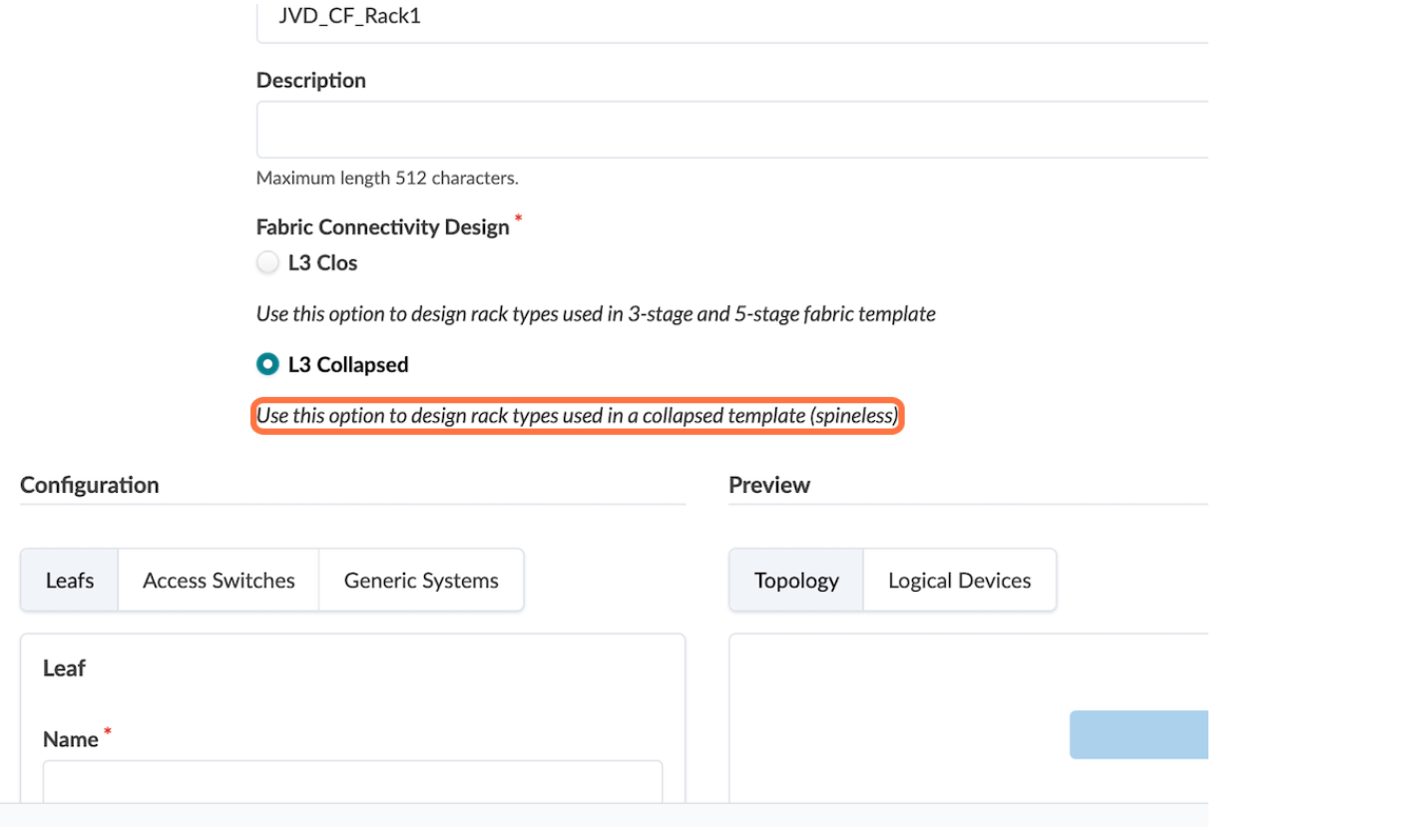
- Create a rack with the name JVD_CF_Rack1 and select
L3 collapsed.
Figure 23: Rack Type Creation in Builder with L3 Collapsed Highlighted
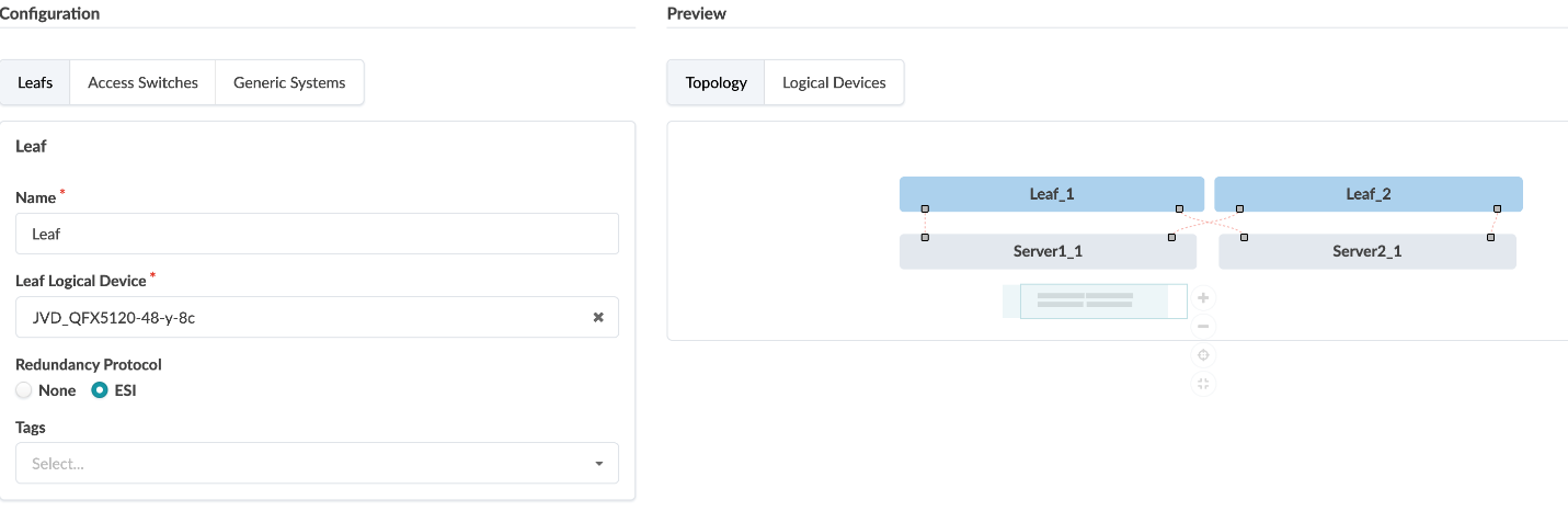
- Under Leafs, select ESI as
the redundancy protocol.
Figure 24: Rack Type Creation in Builder with ESI Under Leafs Highlighted
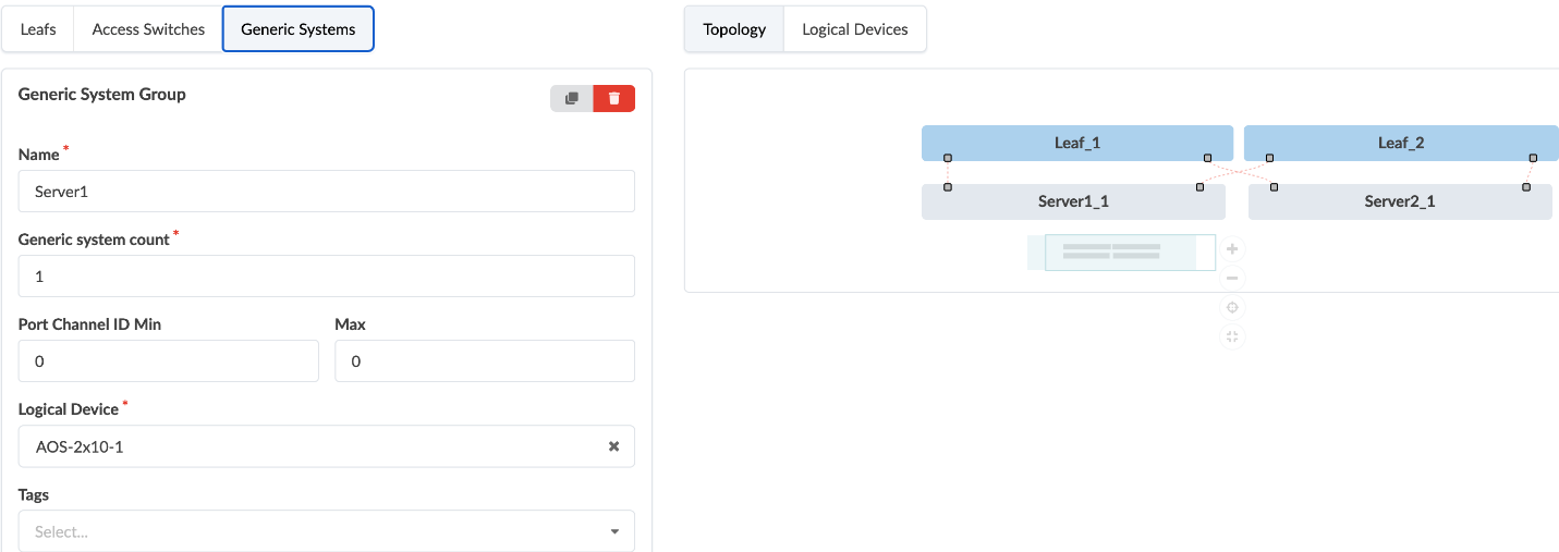
- Under Generic Systems, click Add new
generic system group, and then select
AOS-2x10⁻¹ as the logical device. This action
connects the leafs to the generic systems, such as servers in high
availability mode.
Figure 25: Rack Type Creation in Builder with Generic Systems Selected
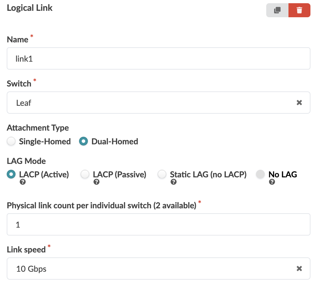
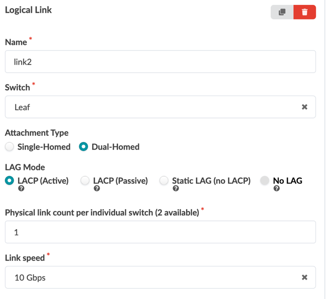
- While still under Generic Systems, click Add logical link and create two logical links: link1 and link2. Both will be dual-homed from server1 and server2 with LACP and have 10 Gbps speeds.
- Click Create when done.
Figure 26: Rack Type Creation in Builder Showing Only the Logical Links Being Created
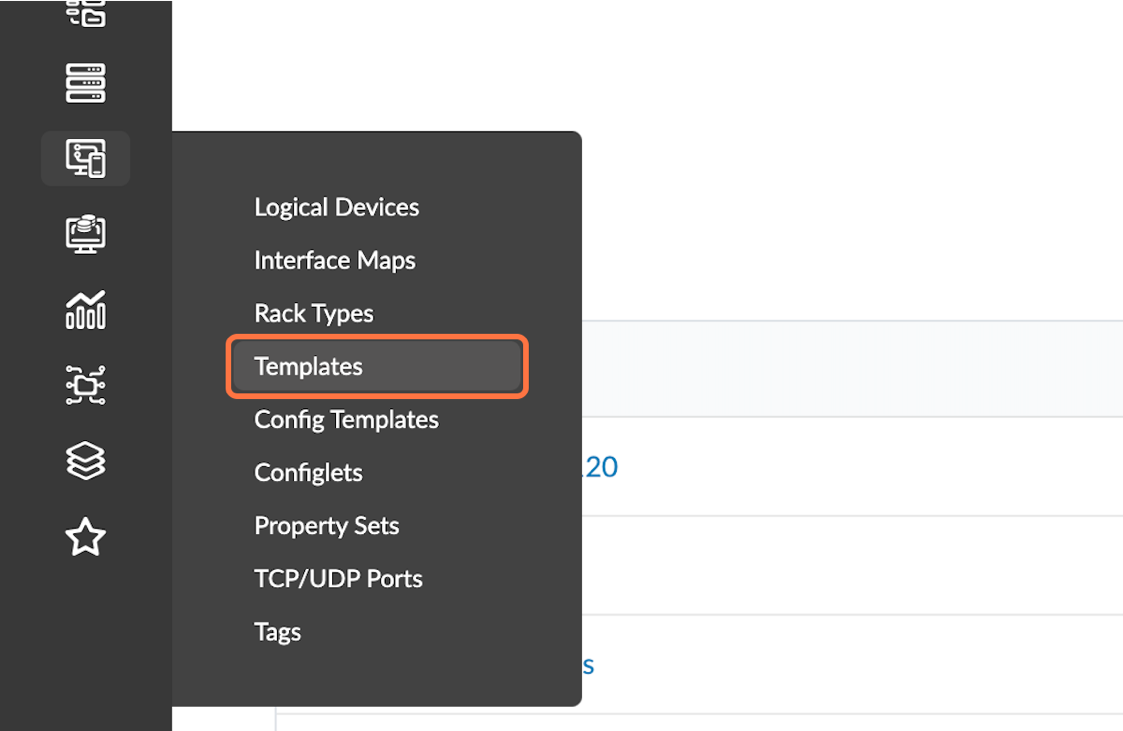
Create Templates
- Navigate to Design > Templates and then
select the Create Template button in the
upper-right corner.
Figure 27: The Design Menu with the Templates Button Highlighted
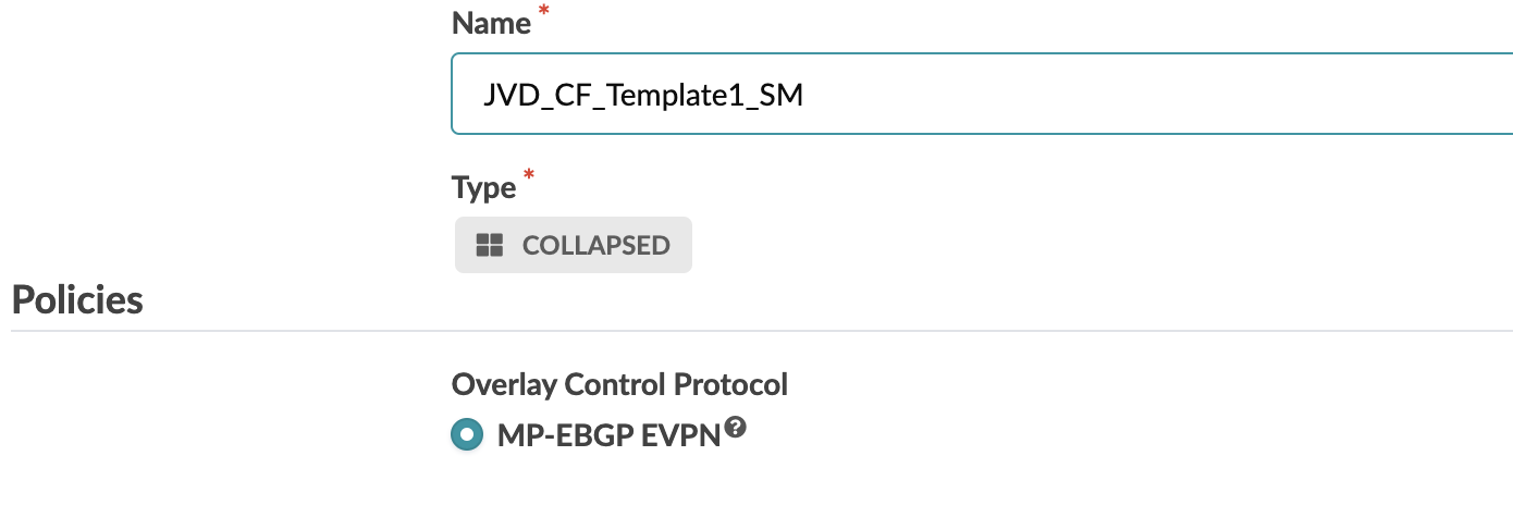
- Name the template JVD_CF_Template1_SM, with
Type Collapsed, and select
MP-BGP-EVPN as the overlay control protocol.
Figure 28: Create Template Pop-up with MP-EBGP-EVPN for the Overlay Control Protocol Selected
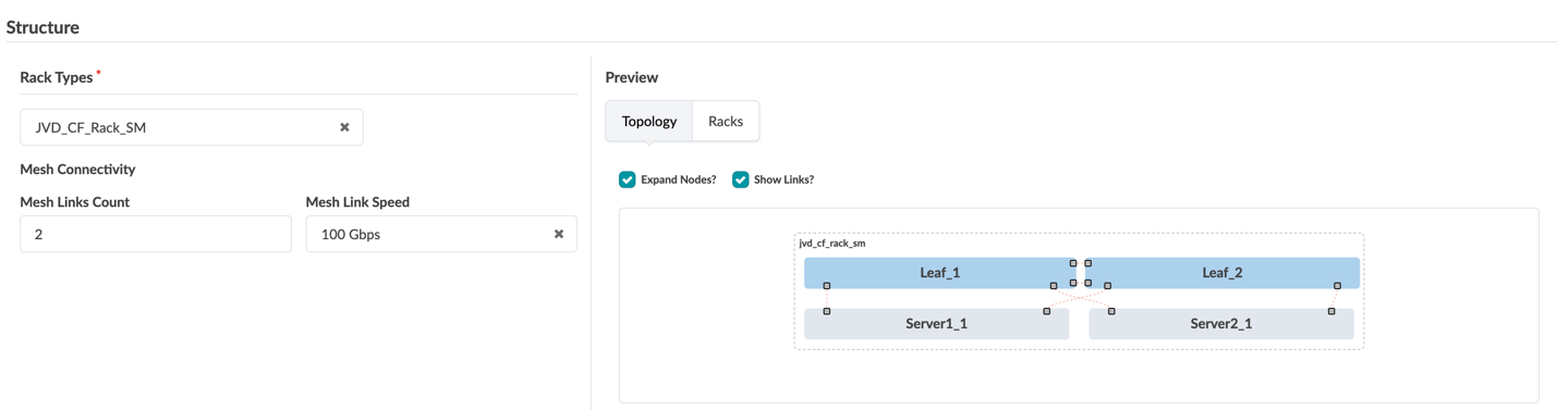
- Select the rack created earlier (JVD_CF_Rack_SM), choose two mesh links, set the mesh link speed to 100 Gbps, and click Create.
Figure 29: Create Template Pop-up with Mesh Links Information Filled In
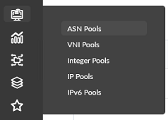
Create ASN POOL
- Navigate to Resources > ASN Pools and then
select the Create ASN Pool button in the
upper-right corner.
Figure 30: Resources Menu with the ASN Pools Button Highlighted
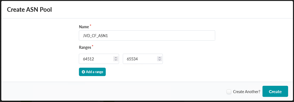
- Create an ASN pool with the name JVD_CF_ASN1 for
internal ASNs. This guide uses 64512-65534 for this ASN Pool.
Figure 31: Create ASN Pool Pop-up Showing the Creation of the ASN Pool JVD_CF_ASN1
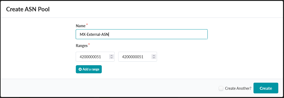
- Create a second ASN pool named MX-External-ASN for external ASNs. This guide uses the single AS 4200000051 for this ASN Pool.
Figure 32: Create ASN Pool Pop-up Showing the Creation of the ASN Pool MX-External-ASN
Create IP and Loopback Pool
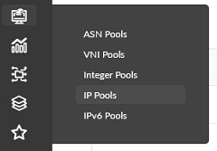
- Navigate to Resources > ASN Pools and then
select the Create IP Pool button in the
upper-right corner
Figure 33: Resources Menu with the ASN Pools Button Highlighted
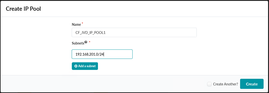
- Create an IP pool named CF_JVD_IP_POOL1 with a subnet
of 192.168.201.0/24 and click Create.
Figure 34: Create IP Pool Pop-up Showing the Creation of the CF_JVD_IP_POOL1 IP Pool
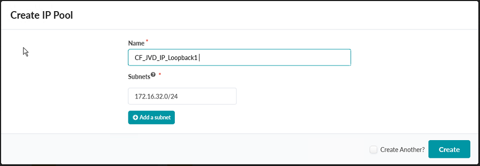
- Create a second IP pool named CF_JVD_IP_Loopback1 with a subnet of 172.16.32.0/24 and click Create.
Figure 35: Create IP Pool Pop-up Showing the Creation of the CF_JVD_IP_Loopback1 IP Pool
Create IP and Loopback Pool
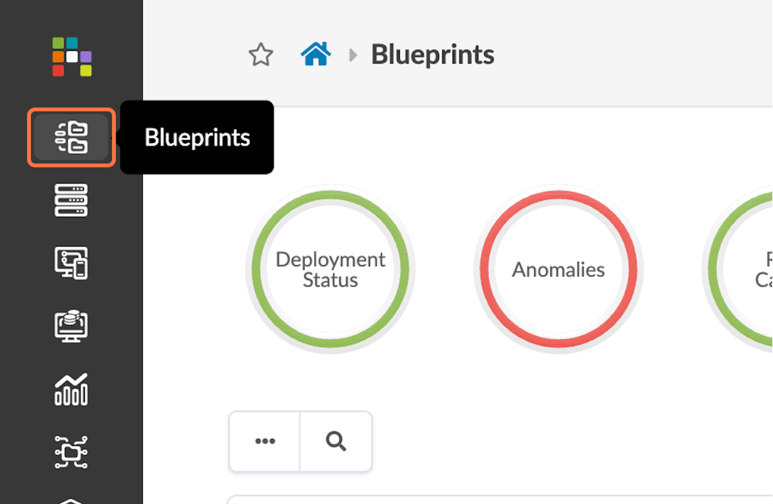
- Navigate to Blueprints and then select the
Create Blueprint button in the upper-right corner.
Figure 36: Blueprints Button on the Main Menu Highlighted
- Name the blueprint JVD_CF_without-Access_BluePrint_SM.
- Select Datacenter for the Reference Design.
- For Filter Templates, select COLLAPSED.
- Select the template created earlier (JVD_CF_Template1_SM) and choose IPv4 for the links.
Figure 37: Create Blueprint Pop-up with Inputs Populated for this JVD
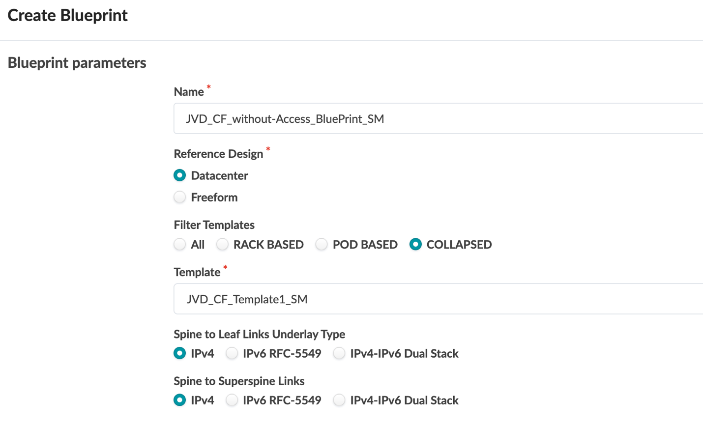
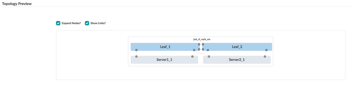
Figure 38: Create Blueprint Pop-up Showing the Topology Preview
Configure Blueprint
- Navigate to Blueprints and then select the blueprint that was just created.
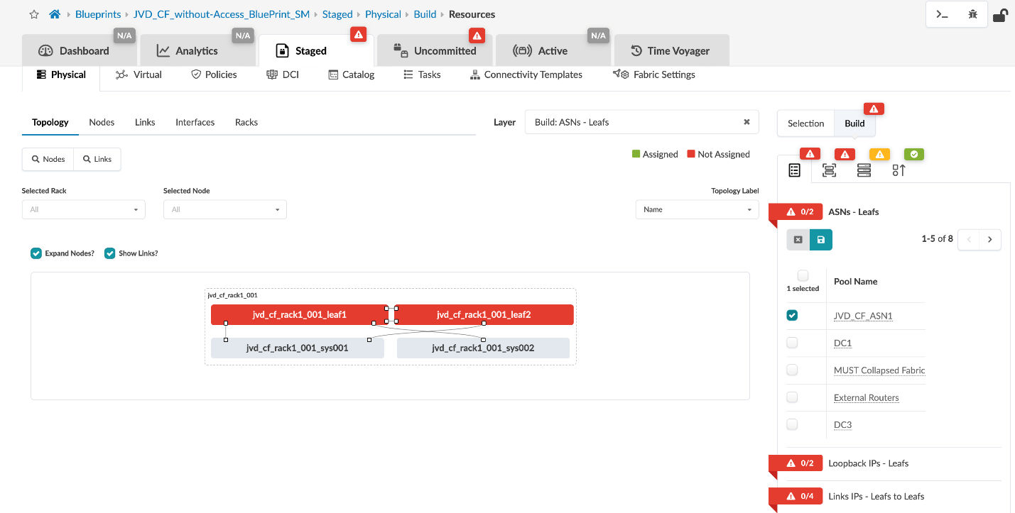
- Go to Staged > Topology and click on the icon beside the words ASNs – Leafs in the panel on the right side of the screen.
- Select the ASN previously created for internal use
(JVD_CF_ASN).
Figure 39: Staged Tab in the JVD_CF_Without-Access_BluePrint_SM Blueprint Showing ASN Assignment Options
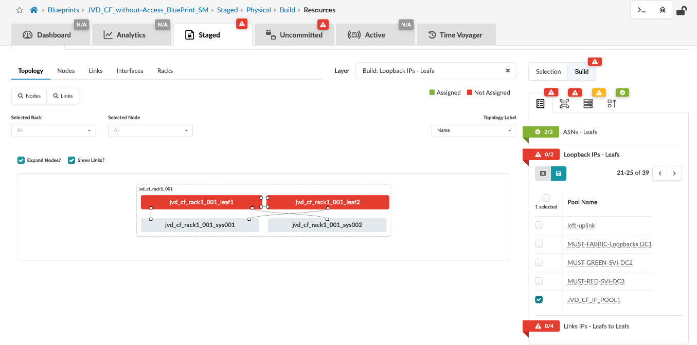
- Next, assign the loopback IP pool that was created earlier.
Figure 40: Staged Tab in the JVD_CF_Without-Access_BluePrint_SM Blueprint Showing Loopback IP Assignment Options
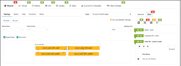
- Select the link IP pool created earlier.
Figure 41: Staged Tab in the JVD_CF_Without-Access_BluePrint_SM Blueprint Showing Link IP Assignment Options
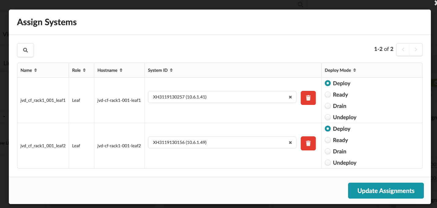
- Deploy the systems by assigning system IDs to the switches.
Figure 42: Staged Tab in the JVD_CF_Without-Access_BluePrint_SM Blueprint Showing System ID Assignment Tab
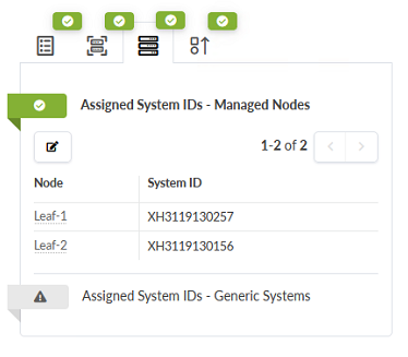
Figure 43: Assign Systems Pop-up in the JVD_CF_Without-Access_BluePrint_SM BluePrint
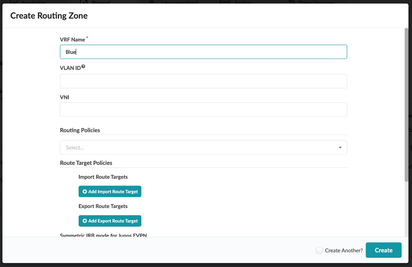
Create VRFs
- From within the JVD_CF_without-Access_BluePrint_SM blueprint, navigate to Staged > Virtual > Routing-Zone and then select the Create Routing Zone button in the upper-right corner of the main content frame.
- Create two VRFs: Blue and Red.
Figure 44: Create Routing Zone Pop-up in the JVD_CF_Without-Access_BluePrint_SM Blueprint
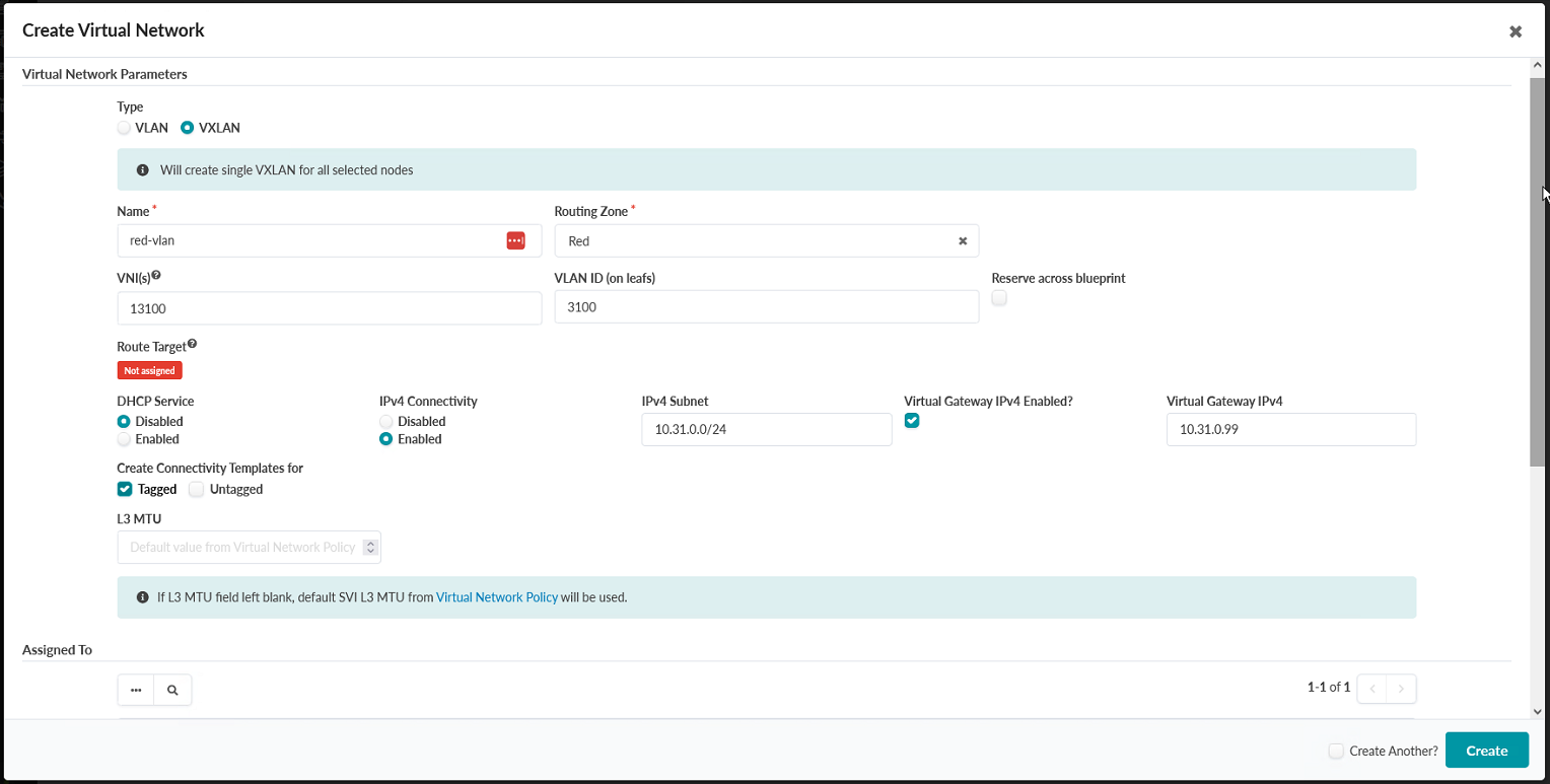
Create Virtual Networks
- From within the JVD_CF_without-Access_BluePrint_SM blueprint, navigate to Staged > Virtual > Virtual Networks and then select the Create Virtual Networks button in the upper-right corner of the main content frame.
- Create VXLANs for the Blue and Red VLANs.
- Create the VXLANs with the following parameters:
First VXLAN Options First VXLAN Values Second VXLAN Options Second VXLAN Values Name red-vlan Name blue-vlan Routing Zone Red Routing Zone Blue VNI 13100 VNI 13200 VLAN ID 3100 VLAN ID 3200 DHCP Service Disabled DHCP Service Disabled IPv4 Connectivity Enabled IPv4 Connectivity Enabled IPv4 Subnet 10.31.0.0/24 IPv4 Subnet 10.32.0.0/24 Virtual Gateway IPv4 Enabled Yes Virtual Gateway IPv4 Enabled Yes Virtual Gateway IPv4 10.31.0.99 Virtual Gateway IPv4 10.32.0.99 Create Connectivity Templates For Tagged Create Connectivity Templates For Tagged Figure 45: Upper Part of the Create Virtual Network Pop-up in the JVD_CF_Without-Access_BluePrint_SM Blueprint
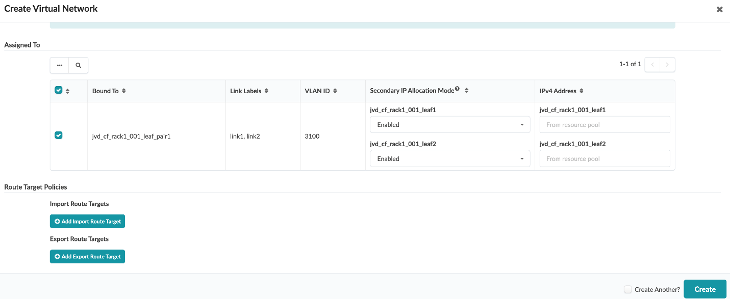
- Before you click Create, ensure you enable both switches.
Figure 46: Upper Part of the Create Virtual Network Pop-up in the JVD_CF_Without-Access_BluePrint_SM Blueprint
Assign Virtual Networking Resources
- From within the JVD_CF_without-Access_BluePrint_SM blueprint, navigate to Staged > Virtual > Routing Zones, and then update the leaf loopback IPs for the Blue and Red routing zones by selecting the icon next to the words Leaf Loopback IPs in the Resource Allocation panel on the right-hand side of the screen.
- Click the edit icon to open the Update
Pool Assignments pop-up. Assign JVD_CF_Loopback1 to
both routing zones.
Figure 47: Staged Tab in the JVD_CF_Without-Access_BluePrint_SM Blueprint Showing Link IP Assignment Options
- Click Update when you are done.
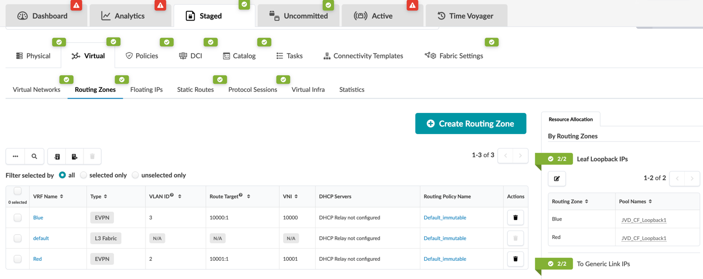
Figure 48: Update Pool Assignments Pop-up in the JVD_CF_Without-Access_BluePrint_SM Blueprint
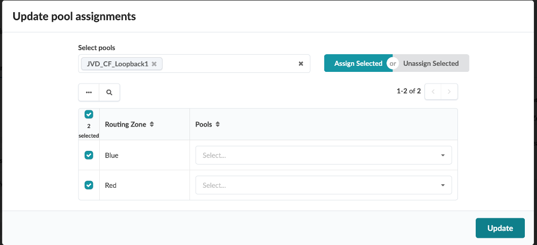
Figure 49: Resource Allocation Panel Showing the EVPN L3 VNIs Section Expanded
-
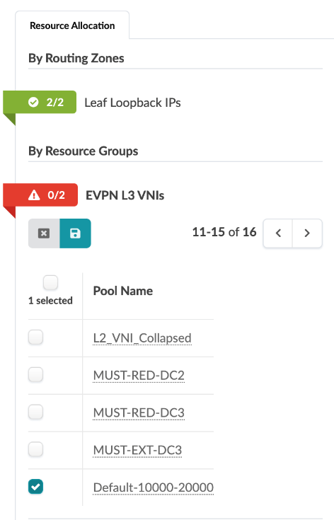 In the Resource Allocation
panel on the right side of the screen, click the icon next to the
words EVPN L3 VNIs.
In the Resource Allocation
panel on the right side of the screen, click the icon next to the
words EVPN L3 VNIs. - Click the edit button, select the default VNI from the list, and click save.
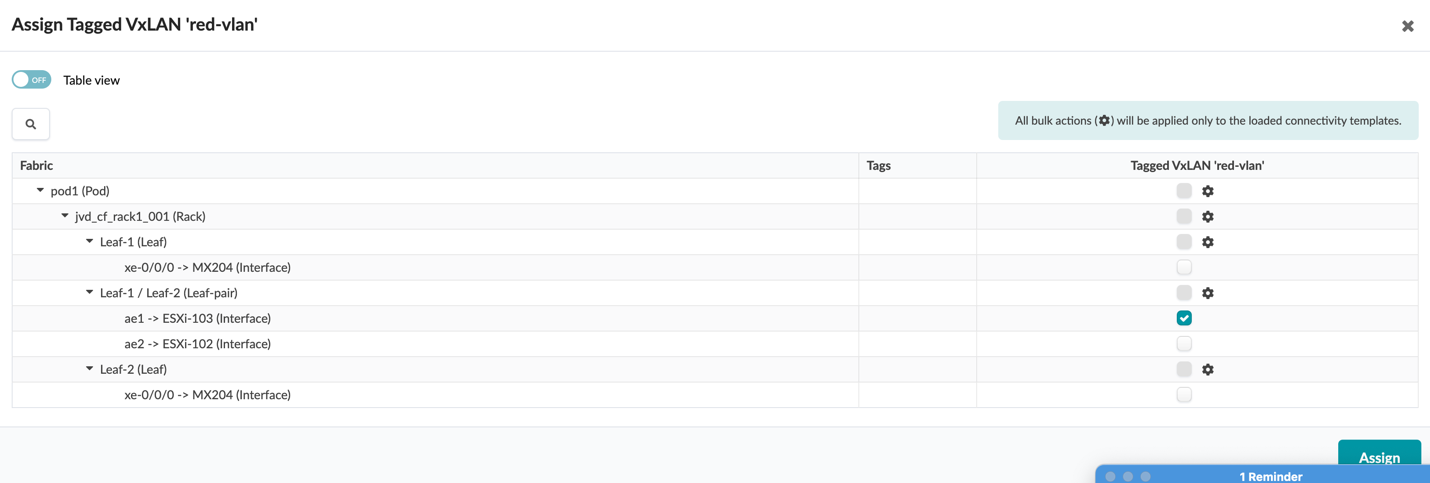
- While still within the JVD_CF_without-Access_BluePrint_SM blueprint, navigate to Staged > Connectivity Templates and assign the Tagged VxLAN ‘Blue-vlan’ to ae2 and the Tagged VxLAN ‘Red-vlan’ to ae1. To do this, click the check box next to each Tagged VxLAN, and then click the Assign icon (it looks like two links in a chain), which appears when you make that selection.
Figure 50: Tagged VXLAN Connectivity Templates and the Control Panel to Assign Them
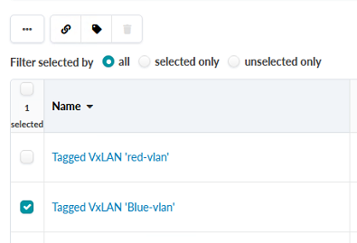
Figure 51: Assign Connectivity Template Pop-up Showing the Tagged VXLAN ‘Blue-vlan’
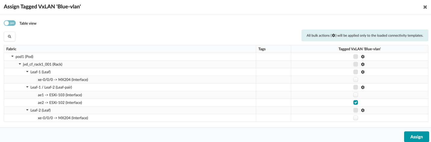
Figure 52: Assign Connectivity Template Pop-up Showing the Tagged VXLAN ‘red-vlan’
Add External Router
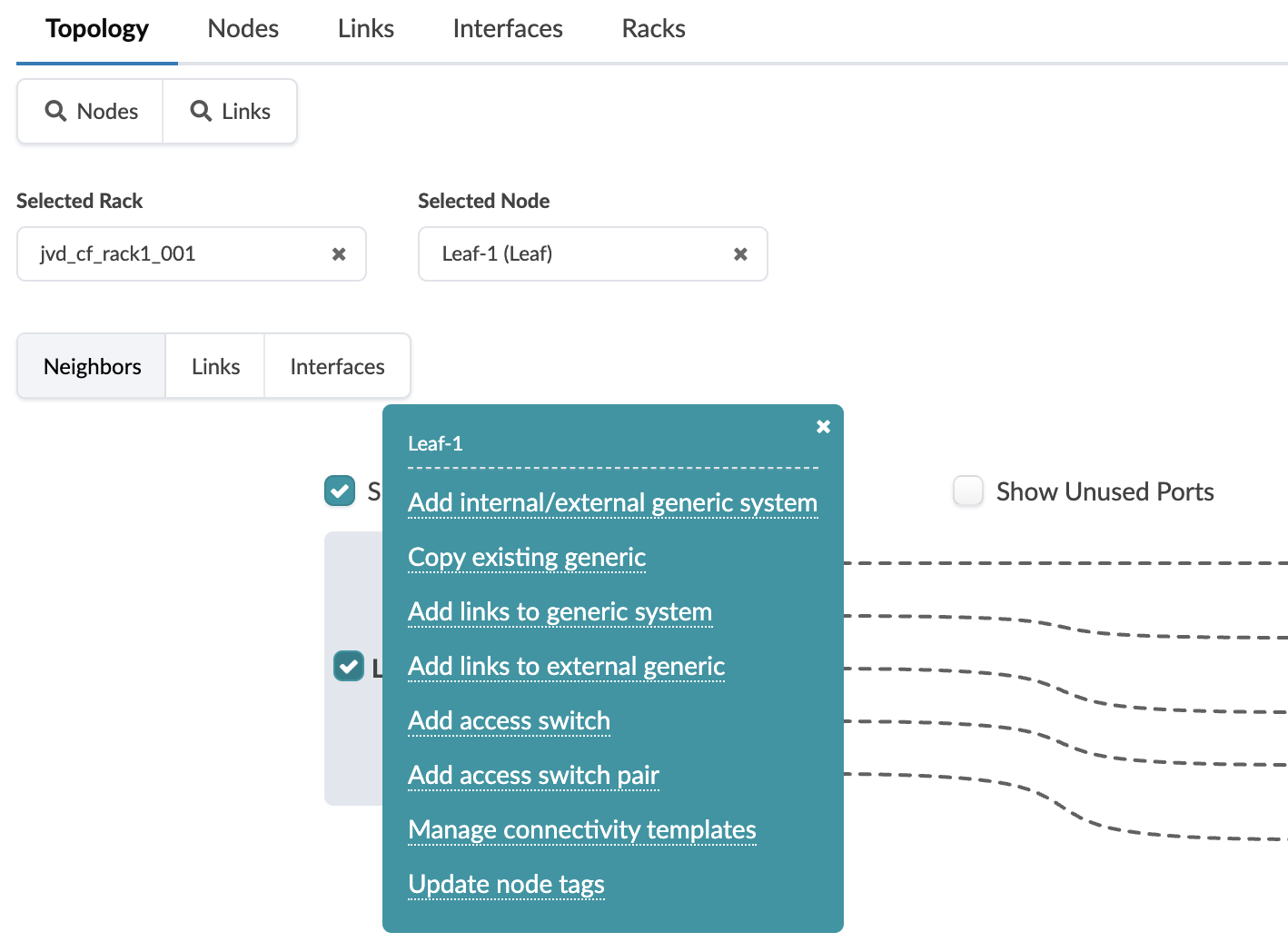
- From within the JVD_CF_without-Access_BluePrint_SM blueprint, navigate to Staged > Physical and click on Leaf-1 in the topology.
- Select the checkbox on Leaf-1 and select Add
internal/external generic system. When complete, you
should see a new link on the graphic.
Figure 53: Leaf-1 Pop-up Showing the Ability to Add an External Generic System
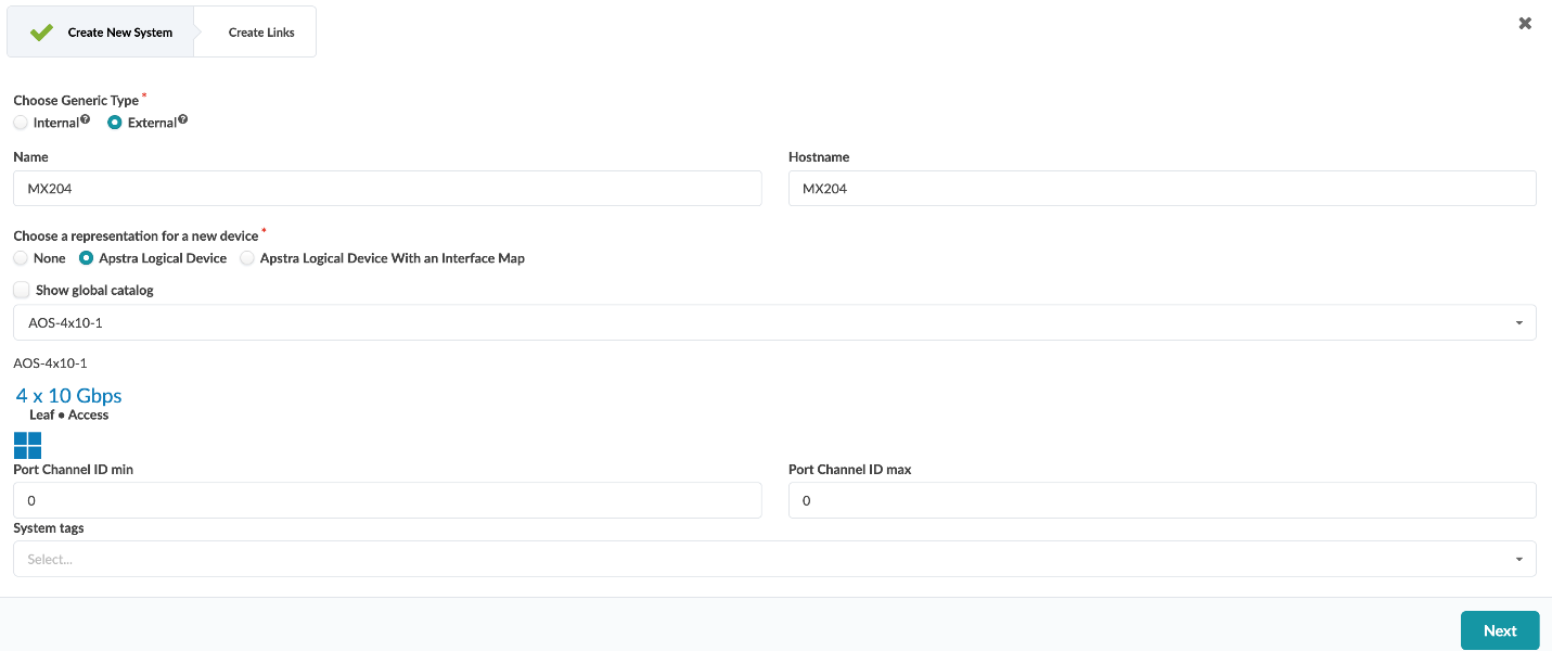
- Create the external system, name it MX204 and
select a logical device with 4x10 Gbps ports, and then click
Next.
Figure 54: First Part of the Assign Internal External Pop-up in the JVD_CF_Without-Access_BluePrint_SM Blueprint
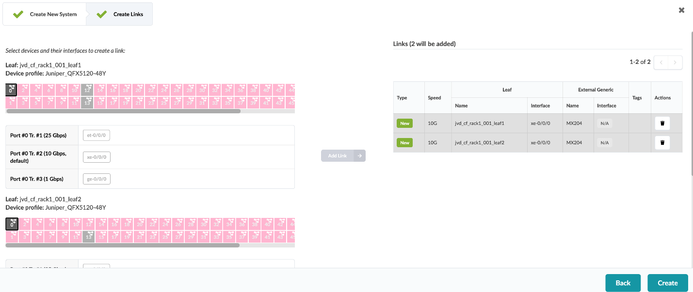
- Create links for the new system to both Leaf-1 and Leaf-2. This is done by selecting an interface, then selecting a port speed.
- Click Add Link. Do this for both switches.
- Click Create once you’re done.
Figure 55: Second Part of the Assign Internal External Pop-up in the JVD_CF_Without-Access_BluePrint_SM Blueprint
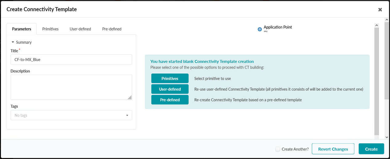
Now that the router has been added, a connectivity template must be created for it.
- Navigate to Staged > Connectivity Templates.
- Click the Add Template button in the upper-right corner.
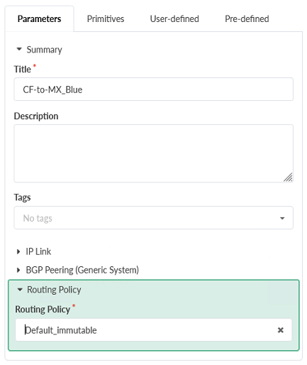
- Name the template CF-to-MX_Blue.
Figure 56: Create Connectivity Template Pop-up in the JVD_CF_Without-Access_BluePrint_SM Blueprint
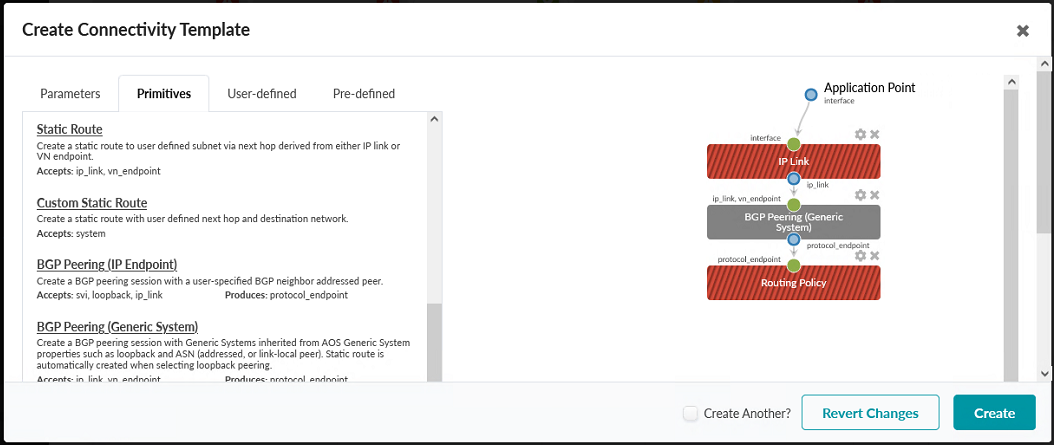
- Click on the Primitives tab and then select
the primitives IP Link, BGP Peering
(Generic System), and Routing Policy.
Figure 57: Primitives Tab in the Create Connectivity Template Pop-up in the JVD_CF_without-Access_BluePrint_SM Blueprint
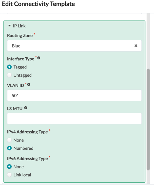
- Click Parameters and expand the IP Link section.
- Choose the routing zone Blue.
- Set the interface type to Tagged and enter VLAN ID of 501.
- Set IPv4 Addressing Type to
Numbered, and IPv6 Addressing
Type to None.
Figure 58: Expanded IP Link Section of the Parameters Tab
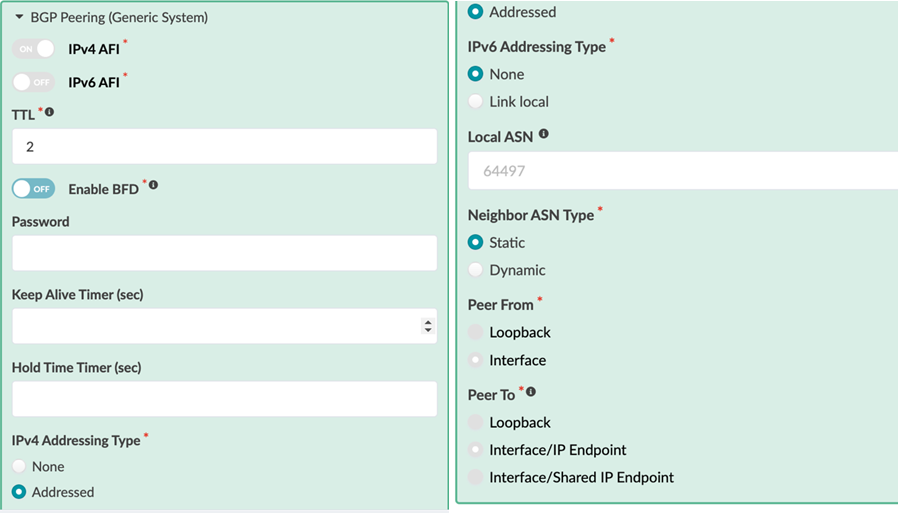
- Expand BGP Peering (Generic System) and configured.
- Set the IPv4 AFI to ON, and the IPv6 AFI to OFF.
- Configure a TTL of 2, and do not enable BFD.
- Set the IPv4 Addressing Type to Addressed, leaving the IPv6 Addressing Type to None.
- Leave the Local ASN Type unconfigured.
- Set the Neighbor ASN Type to
Static.
Figure 59: Expanded IP Link Section of the Parameters Tab
- Expand and configure the Routing Policy section and set it to Default_immutable.
- Click Create.
Figure 60: Expanded Routing Policy Section in the Parameters Tab
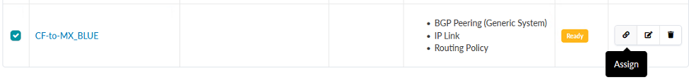
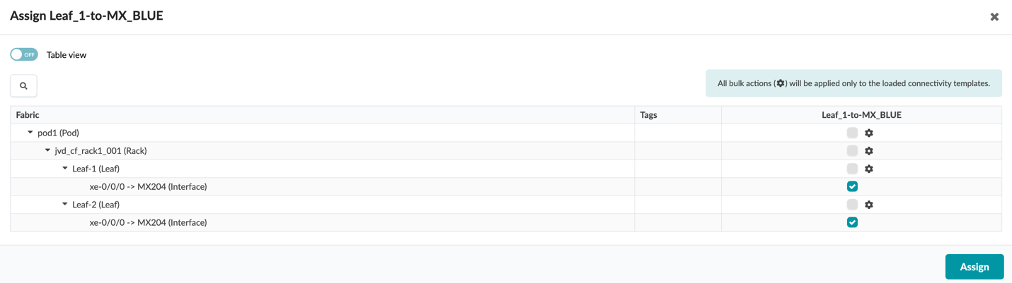
Finally, the connectivity template CF-to-MX_Blue needs to be assigned to the Leaf-1 and Leaf-2 interfaces, which are connected to the external router (MX204).
- Click the Assign icon in line with the CF-to-MX_Blue connectivity template.
- Click the checkboxes to assign the connectivity template to the
interfaces connected to the external router and click
Assign.
Figure 61: CF-to-MX_Blue Connectivity Template Listing, with the Assign Button Highlighted
Figure 62: Assign-CF-to-MX_Blue Pop-up
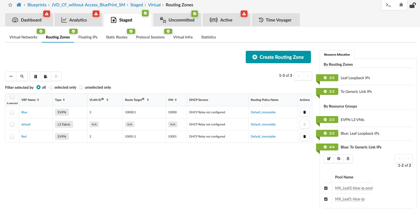
Finally, IP addresses are assigned to interfaces on Leaf-1 and Leaf-2, which are connected to the external router for the Blue VRF. To create IP pools.
- Navigate to Resources > IP Pool from the Create IP and Loopback Pool section above. These IP pools will be named MX_Leaf2-blue-ip and MX_Leaf1-blue-ip.
- Assign the IP pools by navigating to Staged > Routing Zones inside the blueprint.
- Click on the icon next to Blue: To Generic Link IPs in the Routing Zones panel on the right-hand side of the screen to assign the IP pools you just created.
Figure 63: Blue: To Generic Link IPs Section of the Routing Zones Panel is Shown Expanded
The MX204 referenced above is a stand-in for a generic router, and not considered a key component of this JVD. Similar steps can be taken to connect any router. The MX interface configuration is provided below in order to provide an example of how routing on a router is set up to interface with the network described in this JVD.
Below is the MX interface config towards the Leaf-1 and Leaf-2 switches.
set interfaces xe-0/0/3:2 vlan-tagging

set interfaces xe-0/0/3:2 unit 501 description to.blue-DC3-Leaf-1-Cf

set interfaces xe-0/0/3:2 unit 501 vlan-id 501

set interfaces xe-0/0/3:2 unit 501 family inet address 10.202.1.4/31

set interfaces xe-0/0/3:2 unit 502 description to.red-DC3-Leaf-1-Cf

set interfaces xe-0/0/3:2 unit 502 vlan-id 502

set interfaces xe-0/0/3:2 unit 502 family inet address 10.202.1.8/31


set interfaces xe-0/0/3:3 vlan-tagging

set interfaces xe-0/0/3:3 unit 500 family inet address 10.202.1.2/31

set interfaces xe-0/0/3:3 unit 501 description to.blue-DC3-Leaf-2-Cf

set interfaces xe-0/0/3:3 unit 501 vlan-id 501

set interfaces xe-0/0/3:3 unit 501 family inet address 10.202.1.6/31

set interfaces xe-0/0/3:3 unit 502 description to.red-DC3-Leaf-2-Cf

set interfaces xe-0/0/3:3 unit 502 vlan-id 502

set interfaces xe-0/0/3:3 unit 502 family inet address 10.202.1.10/31
Verification
Below is the output from the switches which verify configuration success.
Output from Leaf-1:
root@Leaf-1> show lacp interfaces
Aggregated interface: ae1
    LACP state:       Role   Exp   Def  Dist  Col  Syn  Aggr  Timeout  Activity
      xe-0/0/13      Actor    No    No   Yes  Yes  Yes   Yes     Fast    Active
      xe-0/0/13    Partner    No    No   Yes  Yes  Yes   Yes     Fast    Active
    LACP protocol:        Receive State  Transmit State          Mux State
      xe-0/0/13                 Current   Fast periodic Collecting distributing
Aggregated interface: ae2
    LACP state:       Role   Exp   Def  Dist  Col  Syn  Aggr  Timeout  Activity
      xe-0/0/12      Actor    No    No   Yes  Yes  Yes   Yes     Fast    Active
      xe-0/0/12    Partner    No    No   Yes  Yes  Yes   Yes     Fast    Active
    LACP protocol:        Receive State  Transmit State          Mux State
      xe-0/0/12                 Current   Fast periodic Collecting distributing
{master:0}
root@Leaf-1> show vlans
Routing instance        VLAN name             Tag          Interfaces
default-switch          default               1

evpn-1                  vn3100                3100
                                                           ae1.0*
                                                           vtep.32769*
evpn-1                  vn3200                3200
                                                           ae2.0*
                                                            vtep.32769*
{master:0}
root@Leaf-1> show arp vpn Blue
MAC Address       Address         Name         Interface            Flags
00:50:56:8e:c9:1d 10.32.0.105     10.32.0.105   irb.3200 [ae2.0]     permanent remote
{master:0}
root@Leaf-1> show arp vpn Red
MAC Address       Address         Name           Interface        Flags
00:50:56:8e:b6:03 10.31.0.106     10.31.0.106    irb.3100 [ae1.0]  permanent remote
{master:0}
root@Leaf-1> show ethernet-switching table
MAC flags (S-static MAC, D- dynamic MAC, L-locally learned, P-Persistent static
           SE-statistics enabled, NM-non configured MAC, R-remote PE MAC, O-ovsdb MAC)
Ethernet switching table : 2 entries, 2 learned
Routing instance : evpn-1
Vlan        MAC                 MAC    GBP    Logical    SVLBNH/      Active
name        address             flags  tag    interface  VENH Index   source
vn3100      00:50:56:8e:b6:03   DLR           ae1.0
vn3200      00:50:56:8e:c9:1d   DL            ae2.0
{master:0}
root@Leaf-1> show evpn database
Instance: evpn-1
VLAN  DomainId  MAC address  Active source                 Timestamp        IP address
13100      00:1c:73:00:00:01 irb.3100                      Mar 14 18:01:36  10.31.0.99
13100      00:50:56:8e:b6:03 00:02:00:00:00:00:01:00:00:01 Mar 18 07:35:19  10.31.0.106
13200      00:1c:73:00:00:01 irb.3200                      Mar 14 18:01:36  10.32.0.99
13200      00:50:56:8e:c9:1d 00:02:00:00:00:00:02:00:00:02 Mar 14 18:02:40  10.32.0.105
{master:0}
root@Leaf-1> show interfaces terse | match in
Interface               Admin Link Proto    Local                 Remote
pfe-0/0/0.16383         up    up   inet
                                   inet6
pfh-0/0/0.16383         up    up   inet
pfh-0/0/0.16384         up    up   inet
xe-0/0/0.501            up    up   inet     10.202.1.6/31
xe-0/0/0.502            up    up   inet     10.202.1.10/31
xe-0/0/3.0              up    down inet
xe-0/0/4.0              up    up   inet
xe-0/0/5.0              up    up   inet
xe-0/0/6.0              up    up   inet
xe-0/0/7.0              up    up   inet
xe-0/0/8.0              up    up   inet
xe-0/0/9.0              up    up   inet
xe-0/0/11.0             up    up   inet
xe-0/0/22.0             up    down inet
xe-0/0/23.0             up    down inet
et-0/0/48.0             up    up   inet
et-0/0/49.0             up    up   inet
et-0/0/50.0             up    up   inet
et-0/0/54.0             up    up   inet     192.168.201.0/31
et-0/0/55.0             up    up   inet     192.168.201.2/31
bme0.0                  up    up   inet     128.0.0.1/2
em0.0                   up    up   inet     10.6.1.41/26
em2.32768               up    up   inet     192.168.1.2/24
irb.0                   up    down inet
irb.3100                up    up   inet     10.31.0.99/24
irb.3200                up    up   inet     10.32.0.99/24
jsrv.1                  up    up   inet     128.0.0.127/2
lo0.0                   up    up   inet     172.16.32.0         --> 0/0
lo0.2                   up    up   inet     172.16.32.4         --> 0/0
lo0.3                   up    up   inet     172.16.32.2         --> 0/0
lo0.16384               up    up   inet     127.0.0.1           --> 0/0
lo0.16385               up    up   inet
Output from Leaf-2:
{master:0}
root@Leaf-2> show lacp interfaces
Aggregated interface: ae1
    LACP state:       Role   Exp   Def  Dist  Col  Syn  Aggr  Timeout  Activity
      xe-0/0/13      Actor    No    No   Yes  Yes  Yes   Yes     Fast    Active
      xe-0/0/13    Partner    No    No   Yes  Yes  Yes   Yes     Fast    Active
    LACP protocol:        Receive State  Transmit State          Mux State
      xe-0/0/13                 Current   Fast periodic Collecting distributing
Aggregated interface: ae2
    LACP state:       Role   Exp   Def  Dist  Col  Syn  Aggr  Timeout  Activity
      xe-0/0/12      Actor    No   Yes    No   No   No   Yes     Fast    Active
      xe-0/0/12    Partner    No   Yes    No   No   No   Yes     Fast   Passive
    LACP protocol:        Receive State  Transmit State          Mux State
      xe-0/0/12               Defaulted   Fast periodic           Detached
{master:0}
root@Leaf-2> show vlans
Routing instance        VLAN name             Tag          Interfaces
default-switch          default               1

evpn-1                  vn3100                3100
                                                           ae1.0*
                                                           esi.1816*
                                                           vtep.32769*
evpn-1                  vn3200                3200
                                                           ae2.0
                                                           esi.1815*
                                                           vtep.32769*
{master:0}
root@Leaf-2> show arp vpn Blue
MAC Address       Address      Name          Interface               Flags
00:50:56:8e:c9:1d 10.32.0.105  10.32.0.105   irb.3200 [.local..15]   permanent remote
{master:0}
root@Leaf-2> show arp vpn Red
MAC Address       Address      Name           Interface               Flags
00:50:56:8e:b6:03 10.31.0.106  10.31.0.106    irb.3100 [ae1.0]        permanent remote
{master:0}
root@Leaf-2> show ethernet-switching table
MAC flags (S-static MAC, D-dynamic MAC, L-locally learned, P-Persistent static SE-statistics enabled, NM-non configured MAC, R-remote PE MAC, O-ovsdb MAC)
Ethernet switching table : 2 entries, 2 learned
Routing instance : evpn-1
Vlan    MAC                MAC   GBP Logical   SVLBNH/     Active
name    address            flags tag interface VENH Index  source
vn3100  00:50:56:8e:b6:03  DLR       ae1.0
vn3200  00:50:56:8e:c9:1d  DR        esi.1815  1807       00:02:00:00:00:00:02:00:00:02
{master:0}
root@Leaf-2> show evpn database
Instance: evpn-1
VLAN  DomainId  MAC address   Active source                Timestamp        IP address
13100     00:1c:73:00:00:01  irb.3100                      Mar 14 18:02:00  10.31.0.99
13100     00:50:56:8e:b6:03  00:02:00:00:00:00:01:00:00:01 Mar 18 07:35:43  10.31.0.106
13200     00:1c:73:00:00:01  irb.3200                      Mar 14 18:02:00  10.32.0.99
13200     00:50:56:8e:c9:1d  00:02:00:00:00:00:02:00:00:02 Mar 14 18:03:04  10.32.0.105
{master:0}
root@Leaf-2> show interfaces terse | match in
Interface               Admin Link Proto    Local                 Remote
pfe-0/0/0.16383         up    up   inet
                                   inet6
pfh-0/0/0.16383         up    up   inet
pfh-0/0/0.16384         up    up   inet
xe-0/0/0.501            up    up   inet     10.202.1.4/31
xe-0/0/0.502            up    up   inet     10.202.1.8/31
xe-0/0/1.0              up    down inet
xe-0/0/2.0              up    down inet
xe-0/0/3.0              up    down inet
xe-0/0/4.0              up    up   inet
xe-0/0/5.0              up    up   inet
xe-0/0/6.0              up    down inet
xe-0/0/7.0              up    up   inet
xe-0/0/9.0              up    up   inet
xe-0/0/11.0             up    up   inet
et-0/0/48.0             up    up   inet
et-0/0/49.0             up    up   inet
et-0/0/50.0             up    up   inet
et-0/0/54.0             up    up   inet     192.168.201.1/31
et-0/0/55.0             up    up   inet     192.168.201.3/31
bme0.0                  up    up   inet     128.0.0.1/2
em0.0                   up    up   inet     10.6.1.49/26
em2.32768               up    up   inet     192.168.1.2/24
irb.0                   up    down inet
irb.3100                up    up   inet     10.31.0.99/24
irb.3200                up    up   inet     10.32.0.99/24
jsrv.1                  up    up   inet     128.0.0.127/2
lo0.0                   up    up   inet     172.16.32.1         --> 0/0
lo0.2                   up    up   inet     172.16.32.5         --> 0/0
lo0.3                   up    up   inet     172.16.32.3         --> 0/0
lo0.16384               up    up   inet     127.0.0.1           --> 0/0
lo0.16385               up    up   inet
PING from Host-2 (Red VRF) 10.31.0.106 to Host-1 (Blue VRF) 10.32.0.105:
must@cf-test-2:~$ ping 10.32.0.105
PING 10.32.0.105 (10.32.0.105) 56(84) bytes of data.
64 bytes from 10.32.0.105: icmp_seq=1 ttl=54 time=47.5 ms
64 bytes from 10.32.0.105: icmp_seq=2 ttl=54 time=47.6 ms
64 bytes from 10.32.0.105: icmp_seq=3 ttl=54 time=48.9 ms
^C
--- 10.32.0.105 ping statistics ---
3 packets transmitted, 3 received, 0% packet loss, time 2003ms rtt min/avg/max/mdev = 47.542/47.994/48.884/0.629 ms