ON THIS PAGE
Juniper RDMA-aware Load Balancing (LB) and BGP-DPF – GPU Backend Fabric IP Services
In this section, we describe the strategies employed to address traffic congestion and optimize load distribution within the Backend GPU fabric.
Congestion Management and Congestion Control Configuration
Congestion management and congestion control are implemented using Data Center Quantized Congestion Notification (DCQCN) approach, ensuring traffic fairness and maintaining stability across the lossless fabric.
AI clusters impose unique demands on network infrastructure due to their high-density and low-entropy traffic patterns, characterized by frequent elephant flows and minimal flow variability. Moreover, most AI training workloads require uninterrupted, lossless packet delivery to be completed successfully. Consequently, when designing a network infrastructure for AI traffic flows, the key objectives include maximizing throughput, minimizing latency, and minimizing network interference while ensuring lossless operation. These requirements necessitate the deployment of effective congestion control mechanisms.
Data Center Quantized Congestion Notification (DCQCN) has become the industry-standard method for end-to-end congestion control in RoCEv2 environments. DCQCN provides mechanisms to adjust traffic rates in response to congestion events without relying on packet drops, striking a balance between reducing traffic rates and maintaining ongoing traffic flow.
It is important to note that DCQCN is primarily required in the GPU backend fabric, where the majority of AI workload traffic resides. It is generally unnecessary in the Frontend and Storage Backend fabrics.
DCQCN combines two complementary mechanisms to implement flow and congestion control:
- Priority-based Flow Control (PFC)
- Explicit Congestion Notification (ECN)
Priority-Based Flow Control (PFC) mitigates data loss by pausing traffic transmission for specific traffic classes, based on IEEE 802.1p priorities or DSCP markings mapped to queues.
When congestion is detected, PFC operates by sending PAUSE control frames upstream, requesting the sender to halt transmission of traffic associated with a specific priority. The sender completely stops sending traffic for that priority until the congestion subsides or the PAUSE timer expires.
While PFC prevents packet drops and allows the receiver to catch up, it also impacts application performance for traffic using the affected queues. Furthermore, resuming transmission after a pause can lead to sudden traffic surges, potentially re-triggering congestion. For these reasons, PFC should be configured carefully so that it is used as a last resource.
Explicit Congestion Notification (ECN) offers a proactive congestion signaling mechanism, reducing transmission rates while allowing traffic to continue flowing during congestion periods.
When congestion occurs, ECN bits in the IP header are marked (11), prompting the receiver to generate Congestion Notification Packets (CNPs), which inform the source to throttle its transmission rate. Unlike PFC, ECN aims to gradually reduce congestion without halting traffic completely or triggering packet drops.
Best Practice: Combining PFC and ECN provides the most effective congestion control strategy in a lossless IP fabric supporting RoCEv2. Their parameters must be carefully tuned so that ECN mechanisms are triggered before PFC.
For more detailed guidance, refer to Introduction to Congestion Control in Juniper AI Networks , which outlines best practices for building lossless fabrics for AI workloads using DCQCN (ECN and PFC) congestion control methods alongside Dynamic Load Balancing (DLB). The document is based on validation against DLRM training models and demonstrates how ECN thresholds, PFC parameters, input drops, and tail drops can be monitored and adjusted to optimize fabric performance for RoCEv2 traffic.
While we provide general recommendations and lab-validated parameters, each AI workload may present distinct traffic patterns. Class of Service (CoS) and load balancing attributes might need to be further tuned to match the specific characteristics of a particular model and cluster environment.
This leaf and spines nodes in the JVD are configured with CoS parameters that were determined to provide the best performance.
The following configuration is applied uniformly across all devices in the fabric.
Traffic Classification
set class-of-service classifiers dscp fabric-dscp forwarding-class CNP loss-priority low code-points 110000
set class-of-service classifiers dscp fabric-dscp forwarding-class NO-LOSS loss-priority low code-points 011010
set class-of-service interfaces et-* unit * classifiers dscp fabric-dscp
Traffic classification is based on DSCP and implemented using the fabric-dscp classifier, which defines two forwarding classes: NO-LOSS and CNP . This classifier is applied to all et-* unit * logical interfaces.
All incoming traffic with DSCP 011010 (26) is classified as NO-LOSS, while traffic marked with DSCP 110000 (48) is classified as CNP. All GPU servers are configured to mark RoCEv2 traffic with DSCP 26 and Congestion Notification Packets (CNPs) with DSCP 48.
Refer to the Configuring NVIDIA DCQCN – ECN section of the AI Data Center Network with Juniper Apstra, NVIDIA GPUs, and WEKA Storage JVD and the Configuring AMD DCQCN – ECN section of the AI Data Center Network with Juniper Apstra, AMD GPUs, and Vast Storage JVD for details on how to configure DCQCN parameters on the Nvidia and AMD GPU servers.
set class-of-service forwarding-classes class CNP queue-num 3
set class-of-service forwarding-classes class NO-LOSS queue-num 4
set class-of-service forwarding-classes class NO-LOSS no-loss
set class-of-service forwarding-classes class NO-LOSS pfc-priority
CNP traffic is assigned to output queue 3, while NO-LOSS traffic is assigned to output queue 4.
Queue 4 is configured as a lossless using the no-loss attribute, and it mapped to PFC priority 3. Defining a queue as lossless ensures that packets mapped to this class are not dropped due to congestion—an essential requirement for RoCEv2. Configuring a forwarding class as lossless also impacts buffer allocation on the switch, reserving additional space to support flow control mechanisms such as PFC.
There are two types of buffers:
- Shared Buffer Pool: A global memory space dynamically shared by all ports. It is partitioned between lossy and lossless traffic types. Larger shared buffers help absorb traffic bursts.
- Dedicated Buffer Pool: A reserved portion of memory allocated per port which is then divided among the queues on that port. Though it can be tuned a minimum amount is always reserved by the system. A larger dedicated buffer pool means congestion on one port is less likely to affect traffic on another port because the traffic does not need to use as much shared buffer space. The larger the dedicated buffer pool, the less bursty traffic the switch can handle because there is less dynamic shared buffer memory.
The recommended values for the Shared and Dedicated Buffers in this JVD are as follows:
set class-of-service shared-buffer ingress buffer-partition lossless percent 66
set class-of-service shared-buffer ingress buffer-partition lossless dynamic-threshold 10
set class-of-service shared-buffer ingress buffer-partition lossless-headroom percent 24
set class-of-service shared-buffer ingress buffer-partition lossy percent 10
set class-of-service shared-buffer egress buffer-partition lossless percent 66
set class-of-service shared-buffer egress buffer-partition lossy percent 10
Shared buffers:
- Ingress lossless percent 66: Reserves 66% of the ingress shared buffer space for lossless traffic (e.g., RoCEv2).
- Ingress lossless-headroom percent 24: Carves out an additional 24% of ingress buffer space specifically as headroom for burst absorption. This ensures that RoCEv2 flows have sufficient space to accommodate microbursts while waiting for PFC pause frames to take effect.
- Ingress lossy percent 10: Reserves 10% of ingress shared buffer space for lossy traffic.
- Ingress lossless dynamic-threshold 10: Allows the lossless buffer pool to dynamically expand into unused lossy buffer space by up to 10%, providing flexibility under heavy load./
- Egress lossless percent 66: Reserves 66% of egress shared buffer space for lossless traffic.
- Egress lossy percent 10: Allocates 10% for lossy traffic.
Dedicated Buffers (per-port or per-queue):
- Ingress percent 15: Allocates 15% of the total ingress buffer capacity as dedicated buffers. These are not shared and are reserved for specific traffic classes or ports.
- Egress percent 30:Reserves 30% of egress buffer space for dedicated use.
When this buffer space begins to fill, the PFC mechanism sends Ethernet PAUSE frames to the traffic source instructing it to temporarily halt transmission and prevent packet loss.
Since traffic classification is DSCP-based and interfaces between GPU servers and leaf nodes are untagged, the PFC implementation is DSCP based PFC. The congestion-notification-profile pfc, which is applied to all et-* interfaces, defines operation details for PFC.
set class-of-service interfaces et-* congestion-notification-profile pfc
set class-of-service congestion-notification-profile pfc pfc-watchdog
set class-of-service congestion-notification-profile pfc input dscp code-point 011010 pfc
set class-of-service congestion-notification-profile pfc output ieee-802.1 code-point 011 flow-control-queue 4
The congestion-notification-profile might be interpreted as related to Congestion Notification Packets (ECN). Congestion-notification-profile can also can be found abbreviated as CNP in some documentation. However, this profile defines the behavior of the PFC, not the ECN.
The PFC watchdog function monitors for deadlock or stuck queues caused by persistent PFC pause conditions. If a queue remains paused for too long (indicating possible head-of-line blocking), the watchdog can take corrective actions to avoid traffic stall conditions.
The input dscp code-point 011010 pfc statement specifies that incoming traffic marked with DSCP value 011010 (decimal 26) should trigger PFC when congestion is detected. Essentially, if DSCP 26 (RoCEv2) traffic is experiencing congestion, PFC frames for priority 3 will be generated to pause upstream senders (PFC priority 3 mapped to code point 26). The pause frames will be generated for a priority 3 based on the forwarding-class NO-LOSS configuration previously described.
In the example below:
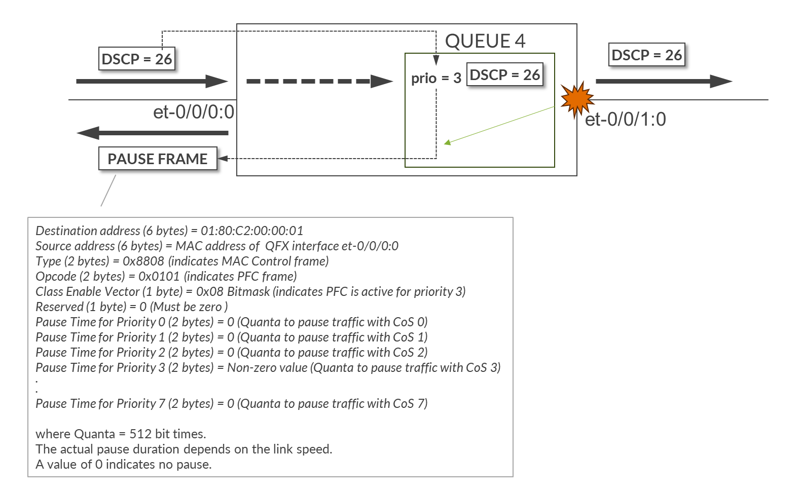
The combination of the following commands applied to interfaces et-0/0/0:0 and et-0/0/1:0, configures the device to classify all inbound traffic with DSCP 26 to the forwarding class NO-LOSS which is assigned to Queue 4, and mapped to pfc-priority 3, makes queue 4 a no-loss queue, and enables PFC for traffic with DSCP 26.
set class-of-service classifiers dscp fabric-dscp forwarding-class NO-LOSS loss-priority low code-points 011010
set class-of-service forwarding-classes class NO-LOSS queue-num 4
set class-of-service forwarding-classes class NO-LOSS no-loss
set class-of-service forwarding-classes class NO-LOSS pfc-priority 3
set class-of-service congestion-notification-profile pfc input dscp code-point 011010 pfc
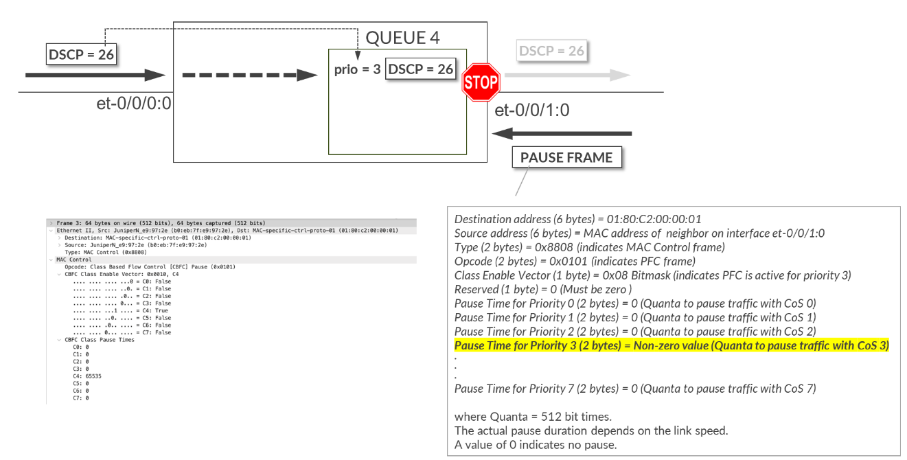
The output ieee-802.1 code-point 011 flow-control-queue 4 statement specifies that when paused frames with priority 3 are received, traffic for queue 4 must stop.
Traffic Scheduling
set class-of-service interfaces et-* scheduler-map sm1
set class-of-service scheduler-maps sm1 forwarding-class CNP scheduler s2-cnp
set class-of-service scheduler-maps sm1 forwarding-class NO-LOSS scheduler s1
The scheduler map sm1 is applied to all et-* interfaces and defines how traffic for each forwarding class is scheduled.
Two schedulers are included:
- s1 for NO-LOSS traffic (queue 4)
- s2-cnp for CNP traffic (queue 3)
NO-LOSS Traffic Scheduling (Scheduler s1)
set class-of-service schedulers s1 drop-profile-map loss-priority any protocol any drop-profile dp1
set class-of-service schedulers s1 explicit-congestion-notification
set class-of-service drop-profiles dp1 interpolate fill-level 55
set class-of-service drop-profiles dp1 interpolate fill-level 90
set class-of-service drop-profiles dp1 interpolate drop-probability 0
set class-of-service drop-profiles dp1 interpolate drop-probability 100
Scheduler s1 controls how traffic in the NO-LOSS forwarding class (queue 4) is serviced. It applies the drop-profile dp1 and enables Explicit Congestion Notification (ECN) marking using the explicit-congestion-notification statement.
Drop profiles in Junos are commonly used to control how aggressively packets are dropped as the queue buffer fills up. However, when ECN is enabled, the profile is used to mark packets instead of dropping them. Marking packets means setting the Congestion Experienced (CE) bit in the IP header based on the configured thresholds.
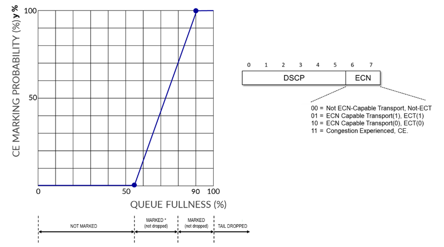
The profile dp1 defines a linear drop curve where:
- At 55% buffer fill, packets are not marked (0% probability).
- At 90% buffer fill, all matching packets are marked (100% probability).
- Between 55% and 90%, the marking probability increases linearly from 0% to 100%.
This approach ensures early congestion feedback to RoCEv2 endpoints while maintaining lossless delivery.
CNP Traffic Scheduling (Scheduler s2-cnp)
Scheduler s2-cnp specifies how CNP traffic in queue 3 is serviced. It assigns the queue strict-high priority and reserves 5% of the interface’s bandwidth:
set class-of-service schedulers s2-cnp transmit-rate percent 5
set class-of-service schedulers s2-cnp priority strict-high
Assigning strict-high priority along with a minimum bandwidth ensures that, during congestion, the Congestion Notification Packets (CNPs) required to trigger source-based rate reduction in DCQCN can be transmitted across the fabric.
Strict-high priority queues are always serviced before any other queues—except for other high-priority queues—which could potentially starve lower-priority traffic. However, the risk of starvation in this case is minimal, because CNP traffic is generally very low volume. As a result, there is no need to rate-limit this queue.
Congestion Management and Congestion Control Verification
The show class-of-service interface <interface> command shows the
scheduler-map, whether congestion-notification is enable and the profile name, as well as
the classifier applied to the interface.
jnpr@stripe1-leaf2> show class-of-service interface et-0/0/0:0
Physical interface: et-0/0/0:0, Index: 1292
Maximum usable queues: 12, Queues in use: 5
Exclude aggregate overhead bytes: disabled
Logical interface aggregate statistics: disabled
  Scheduler map: sm1
  Congestion-notification: Enabled, Name: cnp, Index: 1

  Logical interface: et-0/0/0:0.0, Index: 1256
Object                  Name                   Type                    Index
Classifier              fabric-dscp            dscp                        5
The show class-of-service classifier <classifier-name> command
shows the mapping between DSCP values and forwarding classes and can be used to confirm
correct assignments (CNP => 48, and NO-LOSS => 26)
jnpr@stripe1-leaf2> show class-of-service classifier name fabric-dscp
Classifier: fabric-dscp, Code point type: dscp, Index: 5
  Code point         Forwarding class                    Loss priority
  011010             NO-LOSS                             low
  110000             CNP                                 low
The show class-of-service forwarding-class command
output shows the forwarding-classes to queue mapping. Can be used
to confirmed correct mapping (CNP => queue 3, and NO-LOSS =>
queue 4), as well and the No-loss status and PFC priority of the
NO-LOSS queue.
jnpr@stripe1-leaf2> show class-of-service forwarding-class
Forwarding class                       ID      Queue  Policing priority  No-Loss   PFC priority
  CNP                                  1         3         normal        disabled       0
  NO-LOSS                              2         4         normal        enabled        3
  best-effort                          0         0         normal        disabled       0
  mcast                                8         8         normal        disabled       0
  network-control                      3         7         normal        disabled       0
The show class-of-service scheduler-map sm1 command
output shows the scheduler map sm1 and the
schedulers s1, and s2-cnp,
including their priority, assigned rate, and whether ECN is
enabled.
jnpr@spine1> show class-of-service scheduler-map sm1
 Scheduler map: sm1, Index: 2

  Scheduler: s2-cnp, Forwarding class: CNP, Index: 7
    Transmit rate: 5 percent, Rate Limit: none, Buffer size: unspecified, Buffer Limit: none, Buffer dynamic threshold:
    unspecified,
    Priority: strict-high
    Excess Priority: unspecified, Excess rate: unspecified, Explicit Congestion Notification: disable, ECN pfc no assist:
    disable
    Drop profiles:
      Loss priority   Protocol    Index    Name
      Low             any             0    default-drop-profile
      Medium high     any             0    default-drop-profile
      High            any             0    default-drop-profile


  Scheduler: s1, Forwarding class: NO-LOSS, Index: 6
    Transmit rate: unspecified, Rate Limit: none, Buffer size: unspecified, Buffer Limit: none, Buffer dynamic threshold:
    unspecified,
    Priority: low
    Excess Priority: unspecified, Excess rate: unspecified, Explicit Congestion Notification: enable, ECN pfc no assist: mark
    Drop profiles:
      Loss priority   Protocol    Index    Name
      Low             any             0    dp1
      Medium high     any             0    dp1
      High            any             0    dp1
The show interfaces queue <interface> command
combined with different options and output filter can help
determine if there have been any packet drops, ECN marking, and PFC
Pause frames.
jnpr@stripe1-leaf2> show interfaces queue et-0/0/0:0 forwarding-class CNP
Physical interface: et-0/0/0:0, up, Physical link is Up
  Interface index: 1292, SNMP ifIndex: 703
   Description: facing_spine1:et-0/0/1:0
Forwarding classes: 12 supported, 5 in use
Egress queues: 12 supported, 5 in use
Queue: 3, Forwarding classes: CNP
  Queued:
   Packets              : 	0	0 pps
   Bytes                : 	0	0 bps
  Transmitted:
    Packets              : 	0	0 pps
    Bytes                : 	0	0 bps
    Tail-dropped packets :  	0	0 pps
    Tail-dropped bytes   : 	0	0 bps
    RED-dropped packets  : 	0	0 pps
    RED-dropped bytes    : 	0	0 bps
    ECN-CE packets       :	0	0 pps
    ECN-CE bytes         :	0	0 bps
The output shows the number of CNP packets (DSCP 48) that have been queued. Increments in this value indicate congestion has been detected along the path and the receiver is sending CNP packets in in response to packets with CE = 1.
jnpr@stripe1-leaf2> show interfaces queue et-0/0/0:0 forwarding-class NO-LOSS
Physical interface: et-0/0/0:0, up, Physical link is Up
  Interface index: 1292, SNMP ifIndex: 703
  Description: facing_spine1:et-0/0/1:0
Forwarding classes: 12 supported, 5 in use
Egress queues: 12 supported, 5 in use
Queue: 4, Forwarding classes: NO-LOSS
  Queued:
    Packets              :            1375227202      	0 pps
    Bytes                :         4236817861328      	0 bps
  Transmitted:
    Packets              :            1375227202       	0 pps
    Bytes                :         4236817861328      	0 bps
    Tail-dropped packets :                     0       	0 pps
    Tail-dropped bytes   :                     0        	0 bps
    RED-dropped packets  :                     0     	0 pps
    RED-dropped bytes    :                     0        	0 bps

    ECN-CE packets       :                     0                0 pps
    ECN-CE bytes         :                     0                0 bps
The output shows the number of NO-LOSS packets (DSCP = 26) marked with CE=1. If this number is increasing that is an indication that congestion has been detected.
jnpr@stripe1-leaf2> show interfaces et-0/0/0:0 extensive | match ecn
    Resource errors: 0, ECN Marked packets: 0
The output shows the number of packets marked with CE=1 that have been seen on interface et-0/0/0:0.
jnpr@stripe1-leaf2> show interfaces et-0/0/0:0 extensive | find "MAC Priority Flow Control Statistics"
    MAC Priority Flow Control Statistics:
    Priority :  0        0                0
    Priority :  1        0                0
    Priority :  2        0                0
    Priority :  3        0                0
    Priority :  4        0                0
    Priority :  5        0                0
    Priority :  6        0                0
    Priority :  7        0                0
The output shows the number of PFC pause frames that have been sent/received per priority on interface et-0/0/0:0.
jnpr@stripe1-leaf2> show interfaces et-0/0/0:0 extensive | find "  CoS information:"
  CoS information:
    Direction : Output
    CoS transmit queue
                Bandwidth		Buffer          Priority	Limit
                %	bps	      %	      usec
      3 CNP      5	20000000000   r 	0 	strict-high	none
      4 NO-LOSS  r 	r     	      r 	0       low    	        none
The output shows bandwidth allocation, transmit rate, and queue priority for the forwarding classes CNP, and NO-LOSS on interface et-0/0/0:0.
jnpr@stripe1-leaf2> show interfaces queue buffer-occupancy et-0/0/0:0
Physical interface: et-0/0/0:0, Enabled, Physical link is Up
  Interface index: 1292, SNMP ifIndex: 703
Forwarding classes: 12 supported, 5 in use
Egress queues: 12 supported, 5 in use
            Queue: 0, Forwarding classes: best-effort
                Queue-depth bytes  :
                Peak               : 0
            Queue: 3, Forwarding classes: CNP
                Queue-depth bytes  :
                Peak               : 0
            Queue: 4, Forwarding classes: NO-LOSS
                Queue-depth bytes  :
                Peak               : 0
            Queue: 7, Forwarding classes: network-control
                Queue-depth bytes  :
                Peak               : 254
            Queue: 8, Forwarding classes: mcast
                Queue-depth bytes  :
                Peak               : 0
The output shows peak queue occupancy for each queue on interface et-0/0/0:0.
jnpr@stripe1-leaf2> show class-of-service shared-buffer
Ingress:
  Total Buffer     :  169207 KB
  Dedicated Buffer :  4627 KB
  Shared Buffer    :  143472 KB
    Lossless                   :  94691 KB
    Lossless Headroom          :  34432 KB
    Lossy                      :  14347 KB
    Lossless dynamic threshold :  10
    Lossy dynamic threshold    :  10

  Lossless Headroom Utilization:
  Node Device         Total          Used                  Free
  0                   34432 KB       29235 KB              5197 KB

  ITM0 Headroom Utilization:
  Total           Used            Free
  17216 KB        15260 KB        1956 KB

  ITM1 Headroom Utilization:
  Total           Used            Free
  17216 KB        13975 KB        3241 KB

Egress:
  Total Buffer     :  169207 KB
  Dedicated Buffer :  14162 KB
  Shared Buffer    :  143472 KB
    Lossless                 :  94691 KB
    Lossy                    :  14347 KB
    Lossy dynamic threshold  :  7
The output shows systems buffer allocations.
Juniper ITM (Ingress Traffic Manager) is a component that manages packet buffering and queues.
Load Balancing Failure Scenario – Fallback to DLB
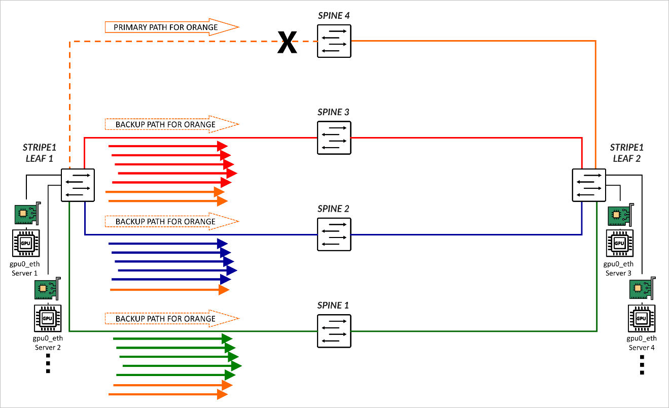
RDMA-aware Load Balancing as described in this document is the primary load balancing solution, but when a link or switch fails traffic will fall back to backup ECMP multipaths and leverages DLB for ECMP decisions. As an example, consider the scenario where 4 spines exist, and 4 colors have been configured:
set policy-options community blue members color:0:2
set policy-options community color-all members color:0:*
set policy-options community green members color:0:1
set policy-options community orange members color:0:4
set policy-options community red members color:0:3
set protocols bgp fabric-advertise route fc00:1:1:1::/64 color green
set protocols bgp fabric-advertise route fc00:1:1:1::/64 backup-color all-colors
set protocols bgp fabric-advertise route fc00:1:1:2::/64 color blue
set protocols bgp fabric-advertise route fc00:1:1:2::/64 backup-color all-colors
set protocols bgp fabric-advertise route fc00:1:1:3::/64 color red
set protocols bgp fabric-advertise route fc00:1:1:3::/64 backup-color all-colors
set protocols bgp fabric-advertise route fc00:1:1:4::/64 color orange
set protocols bgp fabric-advertise route fc00:1:1:4::/64 backup-color all-colors
set protocols bgp group spine1 fabric-color green
set protocols bgp group spine2 fabric-color blue
set protocols bgp group spine3 fabric-color red
set protocols bgp group spine4 fabric-color orange
As a result, traffic is forwarded across their preferred path.
| COLOR | PREFERRED PATH | BACKUP PATHS |
|---|---|---|
| Green | SPINE 1 | SPINE2, SPINE3, SPINE4 |
| Blue | SPINE 2 | SPINE1, SPINE3, SPINE4 |
| Red | SPINE 3 | SPINE1, SPINE2, SPINE4 |
| Orange | SPINE 4 | SPINE1, SPINE2, SPINE3 |
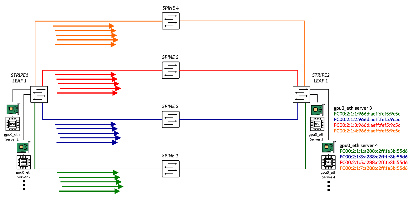
If the link between Stripe 1 Leaf 1 and SPINE 4 fails, orange traffic is rerouted across the backup paths. The load is distributed based on the DLB.
Dynamic Load Balancing (DLB)
Dynamic Load Balancing (DLB) ensures that all paths are utilized more fairly, by not only looking at the packet headers, but also considering real-time link quality based on port load (link utilization) and port queue depth when selecting a path. This method provides better results when multiple long-lived flows moving large amounts of data need to be load balanced.
DLB can be configured in two different modes:
- Per packet mode: packets from the same flow are sprayed across link members of an IP ECMP group, which can cause packets to arrive out of order.
- Flowlet Mode: packets from the same flow are sent across a link member of an IP ECMP group. A flowlet is defined as bursts of the same flow separated by periods of inactivity. If a flow pauses for longer than the configured inactivity timer, it is possible to reevaluate the link members' quality, and for the flow to be reassigned to a different link.
In this JVD, both the leaf and spine nodes are configured to Load Balance traffic using Dynamic Load Balancing flowlet-mode, applied to both IPv4 and IPv6 traffic.
For more information refer to Load Balancing in the Data Center which provides a comprehensive deep dive into the various load-balancing mechanisms and their evolution to suit the needs of the data center.
The following example shows the configuration applied on all devices:
jnpr@gpu-backend-rack1-001-leaf2> show configuration forwarding-options | display set
set forwarding-options hash-key family inet layer-3
set forwarding-options hash-key family inet layer-4
set forwarding-options enhanced-hash-key ecmp-dlb flowlet inactivity-interval 128
set forwarding-options enhanced-hash-key ecmp-dlb flowlet flowset-table-size 2048
set forwarding-options enhanced-hash-key ecmp-dlb ether-type ipv4
set forwarding-options enhanced-hash-key ecmp-dlb ether-type ipv6
set forwarding-options enhanced-hash-key ecmp-dlb sampling-rate 1000000
This configuration defines how flows are identified and the conditions for reassigning them to alternate ECMP paths based on real-time congestion and flow characteristics.
The
hash-key family inet layer-3
and
hash-key family inet layer-4
statements configure the ECMP hashing function to include both IP
addresses and TCP/UDP ports, ensuring granular distribution of IPv4
flows across ECMP paths.
The parameters under enhanced-hash-key modify the DLB hashing algorithm for ECMP traffic forwarding, enabling flowlet-based detection and intelligent reassignment. These include:
-
              ecmp-dlb flowlet
inactivity-interval
Specifies the minimum inter-packet gap (in microseconds) used to detect the boundary between flowlets. A new flowlet is recognized when this threshold is exceeded.
The recommended value is 128 µsec.
-
ecmp-dlb flowset-table-size
Defines the maximum number of flowset (macroflow) entries that can be stored in the DLB hash table. This controls how many active flows the device can track for dynamic reassignment. This value must be a multiple of 8.
The recommended value is 2048.
-
sampling rate:
Defines the sampling rate to detect congestion by configuring the QFX forwarding ASIC to sample the port load on the egress ECMP members, and update quality scores.
The recommended value is 1,000,000, which means 1 in every million packets is sampled, balancing overhead and responsiveness.
-
ether-type ipv4andether-type ipv6:
Enable enhanced ECMP DLB for both IPv4 and IPv6 packets
Load Balancing Verification
To verify the DLB parameters currently in use, you can use the
operational command:
            show forwarding-options
enhanced-hash-key
. The output shows the values
applied by the system for ECMP Dynamic Load Balancing (DLB),
including flowlet behavior.
jnpr@stripe1-leaf1> show forwarding-options enhanced-hash-key

Current RTAG7 Settings
-------------------------
   Hash-Mode                 :layer2-payload
   Hash-Seed                 :112443776

inet  RTAG7 settings:
----------------------
inet packet fields
  protocol                  :yes
  Destination IPv4 Addr     :yes
  Source IPv4 Addr          :yes
  destination L4 Port       :yes
  Source L4 Port            :yes
  Vlan id                   :no
  RDMA Queue Pair           :yes
inet non-packet fields
  incoming port             :yes

inet6  RTAG7 settings:
----------------------
inet6 packet fields
  next-header               :yes
  Destination IPv6 Addr     :yes
  Source IPv6 Addr          :yes
  destination L4 Port       :yes
  Source L4 Port            :yes
  Vlan id                   :no
  RDMA Queue Pair           :yes
inet6 non-packet fields
  incoming port             :yes

Hash-Parameter Settings for ECMP:
------------------------------------
  Hash Function   = CRC16_BISYNC
  Hash offset base = 16
  Hash offset     = 5
  Hash preprocess = 0

Hash-Parameter Settings for LAG:
------------------------------------
  Hash Function   = CRC16_CCITT
  Hash offset base = 0
  Hash offset     = 5
  Hash preprocess = 0

Ecmp Resilient Hash   = Disabled

ECMP DLB Load Balancing Options:
---------------------------------------------------
  Load Balancing Method              : Flowlet
  Inactivity Interval                : 128 (us)
  Flowset Table size                 : 2048 (entries per ECMP)
  Reassignment Probability Threshold : 0
  Reassignment Quality Delta         : 0
  Egress Port Load Weight            : 50
  EgressBytes Min Threshold          : 10
  EgressBytes Max Threshold          : 50
  Sampling Rate                      : 1000000
  Ether Type                         : Ipv4 Ipv6
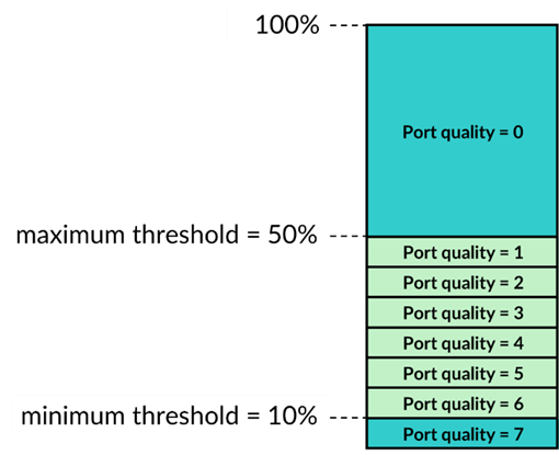
The Egress Port Load Weight shown in the output defines the weights given to port load and port queue length when calculating the port quality score. The EgressBytes Min and EgressBytes Max Thresholds define quality bands. DLB assigns any egress port with a port load falling below this minimum to the highest quality band (7). Any port load larger than the maximum threshold falls into the lowest quality band (0). DLB divides the remaining port load quantities among quality bands 1 through 6.
We recommend maintaining the default values, Egress Port Load Weight (50) EgressBytes Min Threshold (10) and EgressBytes Max Thresholds (50). No configuration is needed to use these values.