ON THIS PAGE
Communication Between GPUs on the Same NUMA Node (e.g., GPU1 ↔ GPU2):
Communication Between GPUs on Different NUMA Nodes (e.g., GPU1 ↔ GPU4):
Editing and reapplying the network configuration (netplan) file
Broadcom BCM957608 Thor2 DCQCN configuration for RDMA Traffic
Configuring DCQN-ECN/PFC and TOS/DSCP for RDMA Traffic attributes directly
Configuring DCQN-ECN/PFC and TOS/DSCP for RDMA Traffic attributes using niccli
Non-volatile memory (NVM) options related to class of service.
Configuring DCQCN and RoCE traffic marking values using bnxt_setupcc.sh
Configuring the server to use the management interface for RCCL control traffic:
AMD configuration
The AI servers covered as part of the JVD include 2 Supermicro AS-8125GS-TNMR2 Dual AMD EPYC 8U GPU and 2 Dell PowerEdge XE9680.
This section provides some guidelines to install and configure the interfaces and other relevant parameters based on the AI JVD lab testing. Always refer to the official manufacturer’s documentation when making changes and for more details.
AMD MI300X Setting BIOS Parameters
Each vendor has different BIOS settings based on differences in its UI and GPU mappings and the servers' internal architectures.
SuperMicro AS-8125GS-TNMR2
Boot the server into Setup mode (the boot to supermicro splash will take several minutes to appear):
| UEFI/BIOS Area | Value |
|---|---|
| Advanced -> NB Configuration | ACS Enable = Disable |
| Advanced -> NB Configuration -> xGMI | xGMI Link Width Control = Manual |
| xGMI Force Link Width Control = Force | |
| xGMI Force Link Width = 2 | |
| xGMI Max Link Width control = Manual | |
| xGMI Link Max Speed = Auto | |
| Advanced -> PCIe/PCI/PnP Configuration | Above 4G Encoding: Enabled |
| Re-Size BAR Support: Enabled | |
| SR-IOV Support: Enabled | |
| Workload = Not Configured |
DELL XE9680
The following BIOS settings are recommended by Dell for their XE9680 AI/ML server. The BIOS settings disable IOMMU and ACS on the host as well.
| UEFI/BIOS Area | Value |
|---|---|
| BIOS -> Processor Settings | Logical Processor = Disable |
| Virtualization Technology = Disable | |
| SubNumaCluster = Disable | |
| MADt Core cluster = Linear | |
| 1 BIOS -> Integrated Devices | Global SRIOV = Disable 1 |
| BIOS -> System Profile Setting | Server System Profile = Performance |
| Workload = Not Configured | |
| BIOS -> System Security | AC Recovery Delay = Random (highly recommended) |
1 Dell recommends “enabling” Global SR-IOV, but on the Dell DUTs in this lab setup, this setting was incompatible with the Thor2 NIC port mode 0 for the storage and frontend fabrics (2x200Gb vs. 1x400Gb), causing the DUT to fault on boot. Consult with your Dell account team for recommendations about this setting in your setup.”
Follow the configuration steps described in the Single-node network configuration for AMD Instinct accelerators — GPU cluster networking documentation. Notice that the disable ACS script used in step 6, must also be run before any workloads, after a server has been rebooted.
Ethernet Network Adapter (NICs) for AI Data centers
AI/ML workloads have increased complexity and scale; networking becomes crucial for efficient job completion times. The Network Adapters (NIC) are the connection points that connect the GPUs to the data center fabrics and hence these NICs should be able to handle large amounts of data and should be able to support high-speed, low-latency communications between GPU servers. Due to this at a minimum, the NICs should be able to support some of the key AI/ML functionality such as below:
- RDMA over Converged Ethernet (RoCE) and congestion control.
- Ability to handle 400G data bidirectional with low latency.
- Advanced congestion control mechanisms that are sensitive and able to react to network congestion and optimize traffic flow.
- Support GPU scalability ensuring robust performance even with increasing GPUs.
For Server NICs, we have two options:
- Broadcom Thor2—The Broadcom Thor2 network adapters were validated for AI/ML workloads and job completion times.
- AMD Pollara—AMD Pollara 400 ethernet network adapters
For more information on AMD Pensando Pollara 400 (ethernet adapter) refer to this link.
Identifying NICs and GPUs mappings
Along with the fabric and GPU server setup, this JVD covers the configuration and setup of ethernet Network Adapters (or NIC) as below. The Broadcom BCM957608 (Thor2) ethernet network adapter was validated in Phase 1. And in Phase2, the AMD Pollara 400 NIC cards are validated.
All 4 servers are equipped with:
- 8 x AMD Instinct MI300X OAM GPUs
and either of the below NICs
- 8 x Single port 400/200/100/50/25/10GbE Broadcom BCM957608 (Thor2) adapter with 400Gbps QDD-400G-DR4 transceivers used to connect to the GPU backend Fabric.
Or
- 8 x Single port 400G and 2 ports 200G and 4 ports 100/50/25G AMD Pensando Pollara 400 ethernet network adapter with Q112-400G-DR4 transceivers used to connect to the GPU backend Fabric.
Dell devices:
- 1 x Mellanox MT2910 Family NVIDIA® ConnectX®-7 SmartNIC with 100Gbps QSFP28 transceivers to connect to the Frontend Fabric
- 2 x Mellanox MT2910 Family NVIDIA® ConnectX®-7 SmartNIC with 200Gbps QDD-2X200G-AOC-5M transceivers to connect to the Frontend Fabric
AMD MI300x GPU Server and NIC Firmware and RCCL libraries
For the purposes of Broadcom Thor 2 NIC validation following are the main OS and firmware versions configured on the MI300x GPU servers:
Broadcom Thor 2 Ethernet Adapter
Below are the details of the Operating System (OS), firmware and AMD libraries installed:
| OS/Firmware | Version |
|---|---|
| Ubuntu | Ubuntu 24.04.2 LTS |
| Broadcom Thor2 NIC Firmware version | 231.2.63.0 |
Following are the libraries installed for RCCL test for Thor2 Network adapter:
| RCCL Test libraries | Version | command |
|---|---|---|
| rocm/noble | 6.4.0.60400-47~24.04 amd64 | apt list rocm |
| Rccl 1 | 2.22.3.60400-47~24.04 amd64 | apt list rccl |
| mpi (Open MPI) | 5.0.8a1 | mpirun –version |
|
UCX |
1.15.0 | /opt/ucx/bin/ucx_info -v |
AMD Pensando Pollara 400 Ethernet Adapter
For the purposes of the AMD Pollara 400 NIC validation, the following are the main OS and firmware versions configured on the MI300x GPU servers:
| OS/Firmware | Version |
|---|---|
| Ubuntu | Ubuntu 22.04.5 LTS |
| AMD Pollara NIC Firmware version | 1.110.0-a-79 |
Output of the ubuntu version 22.04 installed on the MI300 servers.
-
jnpr@mi300-01:~$ cat /etc/os-release

PRETTY_NAME="Ubuntu 22.04.5 LTS"

NAME="Ubuntu"

VERSION_ID="22.04"

VERSION="22.04.5 LTS (Jammy Jellyfish)"

VERSION_CODENAME=jammy

ID=ubuntu

ID_LIKE=debian

HOME_URL="https://www.ubuntu.com/"

SUPPORT_URL="https://help.ubuntu.com/"

BUG_REPORT_URL="https://bugs.launchpad.net/ubuntu/"

PRIVACY_POLICY_URL="https://www.ubuntu.com/legal/terms-and-policies/privacy-policy"
Output of the AMD Pollara 400 NIC card Firmware version
-
jnpr@mi300-01:~$ sudo nicctl show card --detail | grep Firmware

Firmware version               : 1.110.0-a-79

Firmware version               : 1.110.0-a-79

Firmware version               : 1.110.0-a-79

Firmware version               : 1.110.0-a-79

Firmware version               : 1.110.0-a-79

Firmware version               : 1.110.0-a-79

Firmware version               : 1.110.0-a-79

Firmware version               : 1.110.0-a-79
Following are the libraries installed for RCCL test for AMD Pollara 400 NIC adapter:
| RCCL Test libraries | Version | command |
|---|---|---|
| rocm/jammy | 6.3.3.60303-74~22.04 amd64 | apt list rocm |
| Rccl 1 | 7961624 | |
| mpi (Open MPI) | 5.1.0a1 | /opt/ompi/bin/mpirun –version |
|
UCX |
1.20.0 | /opt/ucx/bin/ucx_info -v |
| rccl-tests | revision 6704fc6 | Git branch https://github.com/ROCm/rccl-tests.git |
| ANP Plugin2 |
For more information on installing these software and dependent libraries, high level steps are provided later in section AMD Pollara firmware and dependent libraries, as these steps can only be performed once the NICs and GPUs are mapped as described in sections below.
In this section, we will explore some of the options to find information about and configure the NICs and GPUs.
ROCm Communication Collectives Library (RCCL)
In AMD servers, the ROCm provides multi-GPU and multi-node collective communication primitives optimized for AMD GPUs. These collectives implement send and receive operations such as all-reduce, all-gather, reduce, broadcast, all-to-all, and so on across multiple GPUs in one or more GPU servers.
Communication between GPUs on a single server is implemented using xGMI (inter-chip global memory interconnect), part of AMD's Infinity Fabric technology. The Infinity Fabric is a high-bandwidth, low-latency interconnect for the various components within a system including CPUs, GPUs, memory, NICs, and other devices. xGMI provides socket-to-socket communication, allowing direct CPU-to-CPU or GPU-to-GPU communication.
Communication between different servers is processed by RDMA-capable NICs (e.g., RoCEv2 over Ethernet) and routed across the GPU backend fabric. These NICs can be used by any GPU at any time as there is no hard coded 1-to-1 GPU to NIC mapping. However, the use of preferred communication paths between GPUs and NICs creates the appearance of a 1:1 correspondence.
RCCL will always choose the path that has the best connection between GPUs and between GPUs and NICs, aiming to optimize bandwidth, and latency. Optimized intra-node path will be taken before forwarding inter-node.
The rocm-smi (Radeon Open Compute Platform System
Management Interface) cli provides tools for configuring and
monitoring AMD GPUs. It can be used to identify GPUs hardware
details as well as topology information using the options such
as:
--showproductname: show product details
--showtopo
:
show hardware topology information
--showtopoaccess
:
shows the link accessibility between GPUs
--showtopohops
:
shows the number of hops between GPUs
--showtopotype
:
shows the link type between GPUs
--showtoponuma
:
shows the numa nodes
--shownodesbw: shows the numa nodes bandwidth
--showhw: shows the hardware details
Examples from AMD Instinct MI300X OAM:
The --showproductname shows the GPU series, model,
and vendor along with additional details. The example output shows
AMD
Instinct™ MI300X Platform GPUs are installed in the
server.
-
              jnpr@MI300X-01:/proc$ rocm-smi --showproductname

============================ ROCm System Management Interface ============================

====================================== Product Info ======================================

GPU[0]          : Card Series:          AMD Instinct MI300X OAM

GPU[0]          : Card Model:           0x74a1

GPU[0]          : Card Vendor:          Advanced Micro Devices, Inc. [AMD/ATI]

GPU[0]          : Card SKU:             M3000100

GPU[0]          : Subsystem ID:         0x74a1

GPU[0]          : Device Rev:           0x00

GPU[0]          : Node ID:              2

GPU[0]          : GUID:                 28851

GPU[0]          : GFX Version:          gfx942

GPU[1]          : Card Series:          AMD Instinct MI300X OAM

GPU[1]          : Card Model:           0x74a1

GPU[1]          : Card Vendor:          Advanced Micro Devices, Inc. [AMD/ATI]

GPU[1]          : Card SKU:             M3000100

GPU[1]          : Subsystem ID:         0x74a1

GPU[1]          : Device Rev:           0x00

GPU[1]          : Node ID:              3

GPU[1]          : GUID:                 51499

GPU[1]          : GFX Version:          gfx942

---more--
The --showhw options shows information about the
GPUs in the system, including ID
-
              root@MI300X-01:/sys/kernel/config/bnxt_re/bnxt_re0/ports/1/cc# rocm-smi --showhw -v

====================================== ROCm System Management Interface =================================

=========================================== Concise Hardware Info =======================================

GPU  NODE  DID     GUID   GFX VER  GFX RAS  SDMA RAS  UMC RAS  VBIOS            BUS          PARTITION ID

0    2     0x74a1  28851  gfx942   ENABLED  ENABLED   ENABLED  113-M3000100-102 0000:05:00.0 0

1    3     0x74a1  51499  gfx942   ENABLED  ENABLED   ENABLED  113-M3000100-102 0000:27:00.0 0

2    4     0x74a1  57603  gfx942   ENABLED  ENABLED   ENABLED  113-M3000100-102 0000:47:00.0 0

3    5     0x74a1  22683  gfx942   ENABLED  ENABLED   ENABLED  113-M3000100-102 0000:65:00.0 0

4    6     0x74a1  53458  gfx942   ENABLED  ENABLED   ENABLED  113-M3000100-102 0000:85:00.0 0

5    7     0x74a1  26954  gfx942   ENABLED  ENABLED   ENABLED  113-M3000100-102 0000:A7:00.0 0

6    8     0x74a1  16738  gfx942   ENABLED  ENABLED   ENABLED  113-M3000100-102 0000:C7:00.0 0

7    9     0x74a1  63738  gfx942   ENABLED  ENABLED   ENABLED  113-M3000100-102 0000:E5:00.0 0

==========================================================================================================

============================================ End of ROCm SMI Log =========================================

========================================= VBIOS ==========================================

GPU[0]          : VBIOS version: 113-M3000100-102

GPU[1]          : VBIOS version: 113-M3000100-102

GPU[2]          : VBIOS version: 113-M3000100-102

GPU[3]          : VBIOS version: 113-M3000100-102

GPU[4]          : VBIOS version: 113-M3000100-102

GPU[5]          : VBIOS version: 113-M3000100-102

GPU[6]          : VBIOS version: 113-M3000100-102

GPU[7]          : VBIOS version: 113-M3000100-102

==========================================================================================
The fields are defined as follows:
| GPU | Index of the GPU on the system, starting from 0. |
| NODE | NUMA (Non-Uniform Memory Access) node ID associated with the GPU. Helps identify memory locality. Optimal GPU/NIC mapping often relies on NUMA proximity |
| DID |
Device ID of the GPU. This is a unique identifier for the specific GPU model. Useful for verifying the exact GPU model. For example, 0x74a1 corresponds to an MI300X-series GPU. |
| GUID |
GPU Unique Identifier. This value is specific to each GPU and may relate to its PCIe device. Useful for distinguishing GPUs in a multi-GPU environment. |
| GFX VER |
The version of the GPU architecture (e.g., gfx942 is part of AMD's RDNA2 family). In AMD GPUs, the GFX prefix is part of AMD's internal naming convention for their GPU microarchitecture families. GPU architecture hardware specifications — ROCm Documentation |
| GFX RAS | Status of GPU RAS (Reliability, Availability, Serviceability) features. Indicates error handling. |
| SDMA RAS | Status of SDMA (System Direct Memory Access) RAS features. |
| UMC RAS | Status of Unified Memory Controller (UMC) RAS features. |
| VBIOS |
VBIOS (Video BIOS) version. Indicates the firmware version running on the GPU. Identical firmware version (113-M3000100-102) for all GPUs indicates a uniform configuration. |
| BUS |
PCIe bus address of the GPU. Helps map the GPU to its physical slot. For example, 0000:05:00.0 is the PCIe address. It allows you to correlate GPUs to physical slots or NUMA nodes. |
| PARTITION ID | GPU partition or instance ID. For multi-instance GPUs (e.g., MI300X), this would identify instances.All values are 0 indicating no multi-instance partitioning is enabled for these GPUs. |
The --showbus options show PCI bus related
information, including correspondence between GPU IDs and PCI Bus
IDs.
-
              root@MI300X-01:/sys/kernel/config/bnxt_re/bnxt_re0/ports/1/cc# rocm-smi --showbus -i

============================ ROCm System Management Interface ============================

=========================================== ID ===========================================

GPU[0]          : Device Name:          AMD Instinct MI300X OAM

GPU[0]          : Device ID:            0x74a1

GPU[0]          : Device Rev:           0x00

GPU[0]          : Subsystem ID:         0x74a1

GPU[0]          : GUID:                 28851

GPU[1]          : Device Name:          AMD Instinct MI300X OAM

GPU[1]          : Device ID:            0x74a1

GPU[1]          : Device Rev:           0x00

GPU[1]          : Subsystem ID:         0x74a1

GPU[1]          : GUID:                 51499

GPU[2]          : Device Name:          AMD Instinct MI300X OAM

GPU[2]          : Device ID:            0x74a1

GPU[2]          : Device Rev:           0x00

GPU[2]          : Subsystem ID:         0x74a1

GPU[2]          : GUID:                 57603

---more---

==========================================================================================

======================================= PCI Bus ID =======================================

GPU[0]          : PCI Bus: 0000:05:00.0

GPU[1]          : PCI Bus: 0000:27:00.0

GPU[2]          : PCI Bus: 0000:47:00.0

GPU[3]          : PCI Bus: 0000:65:00.0

GPU[4]          : PCI Bus: 0000:85:00.0

GPU[5]          : PCI Bus: 0000:A7:00.0

GPU[6]          : PCI Bus: 0000:C7:00.0

GPU[7]          : PCI Bus: 0000:E5:00.0

==========================================================================================

================================== End of ROCm SMI Log ===================================
The --showmetrics option provides comprehensive
information about the GPU status and performance, including metrics
such as temperature, clock frequency, power, and pcie
bandwidth.
-
              root@MI300X-01:/sys/kernel/config/bnxt_re/bnxt_re0/ports/1/cc# rocm-smi --showmetrics | grep GPU.0

GPU[0]          : Metric Version and Size (Bytes): 1.6 1664

GPU[0]          : temperature_edge (C): N/A

GPU[0]          : temperature_hotspot (C): 42

GPU[0]          : temperature_mem (C): 35

GPU[0]          : temperature_vrgfx (C): N/A

GPU[0]          : temperature_vrsoc (C): 41

GPU[0]          : temperature_vrmem (C): N/A

GPU[0]          : average_gfx_activity (%): 0

GPU[0]          : average_umc_activity (%): 0

GPU[0]          : average_mm_activity (%): N/A

GPU[0]          : average_socket_power (W): N/A

GPU[0]          : energy_accumulator (15.259uJ (2^-16)): 4291409153508

GPU[0]          : system_clock_counter (ns): 508330314785091

GPU[0]          : average_gfxclk_frequency (MHz): N/A

GPU[0]          : average_socclk_frequency (MHz): N/A

GPU[0]          : average_uclk_frequency (MHz): N/A

GPU[0]          : average_vclk0_frequency (MHz): N/A

GPU[0]          : average_dclk0_frequency (MHz): N/A

GPU[0]          : average_vclk1_frequency (MHz): N/A

GPU[0]          : average_dclk1_frequency (MHz): N/A

GPU[0]          : current_gfxclk (MHz): 134

GPU[0]          : current_socclk (MHz): 28

GPU[0]          : current_uclk (MHz): 900

GPU[0]          : current_vclk0 (MHz): 29

GPU[0]          : current_dclk0 (MHz): 22

GPU[0]          : current_vclk1 (MHz): 29

GPU[0]          : current_dclk1 (MHz): 22

GPU[0]          : throttle_status: N/A

GPU[0]          : current_fan_speed (rpm): N/A

GPU[0]          : pcie_link_width (Lanes): 16

GPU[0]          : pcie_link_speed (0.1 GT/s): 320

GPU[0]          : gfx_activity_acc (%): 682809151

GPU[0]          : mem_activity_acc (%): 60727622

GPU[0]          : temperature_hbm (C): ['N/A', 'N/A', 'N/A', 'N/A']

GPU[0]          : firmware_timestamp (10ns resolution): 507863813273800

GPU[0]          : voltage_soc (mV): N/A

GPU[0]          : voltage_gfx (mV): N/A

GPU[0]          : voltage_mem (mV): N/A

GPU[0]          : indep_throttle_status: N/A

GPU[0]          : current_socket_power (W): 123

GPU[0]          : vcn_activity (%): [0, 0, 0, 0]

GPU[0]          : gfxclk_lock_status: 0

GPU[0]          : xgmi_link_width: 0

GPU[0]          : xgmi_link_speed (Gbps): 0

GPU[0]          : pcie_bandwidth_acc (GB/s): 626812796806

GPU[0]          : pcie_bandwidth_inst (GB/s): 18

---more---
The --showtopo options show how the GPUs in the
systems can communicate with each other via XGMI (Link Type)
representing one hop between any two GPUs. The weight of 15
indicates this direct communication is the preferred path.
-
              jnpr@MI300X-01:~$ rocm-smi --showtopo

============================ ROCm System Management Interface ============================

================================ Weight between two GPUs =================================

        GPU0    GPU1    GPU2    GPU3    GPU4    GPU5    GPU6    GPU7

GPU0    0       15      15      15      15      15      15      15

GPU1    15      0       15      15      15      15      15      15

GPU2    15      15      0       15      15      15      15      15

GPU3    15      15      15      0       15      15      15      15

GPU4    15      15      15      15      0       15      15      15

GPU5    15      15      15      15      15      0       15      15

GPU6    15      15      15      15      15      15      0       15

GPU7    15      15      15      15      15      15      15      0

================================= Hops between two GPUs ==================================

        GPU0    GPU1    GPU2    GPU3    GPU4    GPU5    GPU6    GPU7

GPU0    0       1       1       1       1       1       1       1

GPU1    1       0       1       1       1       1       1       1

GPU2    1       1       0       1       1       1       1       1

GPU3    1       1       1       0       1       1       1       1

GPU4    1       1       1       1       0       1       1       1

GPU5    1       1       1       1       1       0       1       1

GPU6    1       1       1       1       1       1       0       1

GPU7    1       1       1       1       1       1       1       0

=============================== Link Type between two GPUs ===============================

        GPU0    GPU1    GPU2    GPU3    GPU4    GPU5    GPU6    GPU7

GPU0    0       XGMI    XGMI    XGMI    XGMI    XGMI    XGMI    XGMI

GPU1    XGMI    0       XGMI    XGMI    XGMI    XGMI    XGMI    XGMI

GPU2    XGMI    XGMI    0       XGMI    XGMI    XGMI    XGMI    XGMI

GPU3    XGMI    XGMI    XGMI    0       XGMI    XGMI    XGMI    XGMI

GPU4    XGMI    XGMI    XGMI    XGMI    0       XGMI    XGMI    XGMI

GPU5    XGMI    XGMI    XGMI    XGMI    XGMI    0       XGMI    XGMI

GPU6    XGMI    XGMI    XGMI    XGMI    XGMI    XGMI    0       XGMI

GPU7    XGMI    XGMI    XGMI    XGMI    XGMI    XGMI    XGMI    0

======================================= Numa Nodes =======================================

GPU[0]          : (Topology) Numa Node: 0

GPU[0]          : (Topology) Numa Affinity: 0

GPU[1]          : (Topology) Numa Node: 0

GPU[1]          : (Topology) Numa Affinity: 0

GPU[2]          : (Topology) Numa Node: 0

GPU[2]          : (Topology) Numa Affinity: 0

GPU[3]          : (Topology) Numa Node: 0

GPU[3]          : (Topology) Numa Affinity: 0

GPU[4]          : (Topology) Numa Node: 1

GPU[4]          : (Topology) Numa Affinity: 1

GPU[5]          : (Topology) Numa Node: 1

GPU[5]          : (Topology) Numa Affinity: 1

GPU[6]          : (Topology) Numa Node: 1

GPU[6]          : (Topology) Numa Affinity: 1

GPU[7]          : (Topology) Numa Node: 1

GPU[7]          : (Topology) Numa Affinity: 1

================================== End of ROCm SMI Log ===================================

Usage:

        cma_roce_tos OPTIONS

Options:

        -h              show this help

        -d <dev>        use IB device <dev> (default mlx5_0)

        -p <port>       use port <port> of IB device (default 1)

        -t <TOS>        set TOS of RoCE RDMA_CM applications (0)
The link type, number of hops, and weight can be also obtained
using the specific options
--showtopoweight
,
--showtopotype, and
–showtopoweight:
-
              jnpr@MI300X-01:~/SCRIPTS$ rocm-smi --showtopoweight

============================ ROCm System Management Interface ============================

================================ Weight between two GPUs =================================

       GPU0         GPU1         GPU2         GPU3         GPU4         GPU5         GPU6         GPU7

GPU0   0            15           15           15           15           15           15           15

GPU1   15           0            15           15           15           15           15           15

GPU2   15           15           0            15           15           15           15           15

GPU3   15           15           15           0            15           15           15           15

GPU4   15           15           15           15           0            15           15           15

GPU5   15           15           15           15           15           0            15           15

GPU6   15           15           15           15           15           15           0            15

GPU7   15           15           15           15           15           15           15           0

================================== End of ROCm SMI Log ===================================

jnpr@MI300X-01:~/SCRIPTS$ rocm-smi --showtopohops

============================ ROCm System Management Interface ============================

================================= Hops between two GPUs ==================================

       GPU0         GPU1         GPU2         GPU3         GPU4         GPU5         GPU6         GPU7

GPU0   0            1            1            1            1            1            1            1

GPU1   1            0            1            1            1            1            1            1

GPU2   1            1            0            1            1            1            1            1

GPU3   1            1            1            0            1            1            1            1

GPU4   1            1            1            1            0            1            1            1

GPU5   1            1            1            1            1            0            1            1

GPU6   1            1            1            1            1            1            0            1

GPU7   1            1            1            1            1            1            1            0

================================== End of ROCm SMI Log ===================================

jnpr@MI300X-01:~/SCRIPTS$ rocm-smi --showtopotype

============================ ROCm System Management Interface ============================

=============================== Link Type between two GPUs ===============================

       GPU0         GPU1         GPU2         GPU3         GPU4         GPU5         GPU6         GPU7

GPU0   0            XGMI         XGMI         XGMI         XGMI         XGMI         XGMI         XGMI

GPU1   XGMI         0            XGMI         XGMI         XGMI         XGMI         XGMI         XGMI

GPU2   XGMI         XGMI         0            XGMI         XGMI         XGMI         XGMI         XGMI

GPU3   XGMI         XGMI         XGMI         0            XGMI         XGMI         XGMI         XGMI

GPU4   XGMI         XGMI         XGMI         XGMI         0            XGMI         XGMI         XGMI

GPU5   XGMI         XGMI         XGMI         XGMI         XGMI         0            XGMI         XGMI

GPU6   XGMI         XGMI         XGMI         XGMI         XGMI         XGMI         0            XGMI

GPU7   XGMI         XGMI         XGMI         XGMI         XGMI         XGMI         XGMI         0

================================== End of ROCm SMI Log ===================================
The --shownodesbw shows the bandwidth available
internally for GPU to GPU internal
communication:
-
              jnpr@MI300X-01:/home/ben$ rocm-smi --shownodesbw

============================ ROCm System Management Interface ============================

======================================= Bandwidth ========================================

        GPU0    GPU1    GPU2    GPU3    GPU4    GPU5    GPU6    GPU7

GPU0    N/A     50000-50000     50000-50000     50000-50000     50000-50000     50000-50000     50000-50000     50000-50000

GPU1    50000-50000     N/A     50000-50000     50000-50000     50000-50000     50000-50000     50000-50000     50000-50000

GPU2    50000-50000     50000-50000     N/A     50000-50000     50000-50000     50000-50000     50000-50000     50000-50000

GPU3    50000-50000     50000-50000     50000-50000     N/A     50000-50000     50000-50000     50000-50000     50000-50000

GPU4    50000-50000     50000-50000     50000-50000     50000-50000     N/A     50000-50000     50000-50000     50000-50000

GPU5    50000-50000     50000-50000     50000-50000     50000-50000     50000-50000     N/A     50000-50000     50000-50000

GPU6    50000-50000     50000-50000     50000-50000     50000-50000     50000-50000     50000-50000     N/A     50000-50000

GPU7    50000-50000     50000-50000     50000-50000     50000-50000     50000-50000     50000-50000     50000-50000     N/A

Format:         min-max;        Units:  mps

"0-0"   min-max         bandwidth       indicates       devices         are     not     connected       directly

================================== End of ROCm SMI Log ===================================
rocm-smi
-h
For more information about ROCm-SMI as well as for the newer AMD-SMI cli please check: ROCm Documentation, AMD SMI documentation, ROCm and AMD SMI
NICs and GPUs mappings
Next is to perform mapping of the NIC to GPUs as shown in the below steps. These will be the same for both Thor2 and AMD Pollara 400 NIC.
The information from other commands can be combined with some of the options above to find correlation between GPU and NICs following these steps:
-
Identify NUMA Nodes and GPUs
Use the output from
rocm-smi --showtoponumaor justrocm-smi --showtopoto find mappings between GPUs and NUMA nodes.Look for NUMA Affinity for each GPU in the output. A description of what this attribute means is included later in this section.
Note which GPUs are associated with which NUMA nodes.
Example:
-
jnpr@MI300X-01:/proc$ rocm-smi --showtoponuma

============================ ROCm System Management Interface ============================

======================================= Numa Nodes =======================================

GPU[0]          : (Topology) Numa Node: 0

GPU[0]          : (Topology) Numa Affinity: 0

GPU[1]          : (Topology) Numa Node: 0

GPU[1]          : (Topology) Numa Affinity: 0

GPU[2]          : (Topology) Numa Node: 0

GPU[2]          : (Topology) Numa Affinity: 0

GPU[3]          : (Topology) Numa Node: 0

GPU[3]          : (Topology) Numa Affinity: 0

GPU[4]          : (Topology) Numa Node: 1

GPU[4]          : (Topology) Numa Affinity: 1

GPU[5]          : (Topology) Numa Node: 1

GPU[5]          : (Topology) Numa Affinity: 1

GPU[6]          : (Topology) Numa Node: 1

GPU[6]          : (Topology) Numa Affinity: 1

GPU[7]          : (Topology) Numa Node: 1

GPU[7]          : (Topology) Numa Affinity: 1

================================== End of ROCm SMI Log ===================================
GPU 0–3 → NUMA Node 0
GPU 4–7 → NUMA Node 1
-
- Identify NUMA Nodes for NICs
Navigate to the
/sys/class/net/directory and check the NUMA node affinity for each network interface (excluding lo or docker interfaces):-
for iface in $(ls /sys/class/net/ | grep -Ev '^(lo|docker)'); do

    numa_node=$(cat /sys/class/net/$iface/device/numa_node 2>/dev/null)

    echo "Interface: $iface, NUMA Node: $numa_node"

done
Note the NUMA node affinity for each NIC interface.
EXAMPLE:
-
jnpr@MI300X-01:~/SCRIPTS$ for iface in $(ls /sys/class/net/ | grep -Ev '^(lo|docker)'); do

    numa_node=$(cat /sys/class/net/$iface/device/numa_node 2>/dev/null)

    echo "Interface: $iface, NUMA Node: $numa_node"

done

Interface: ens61f1np1, NUMA Node: 1

Interface: enxbe3af2b6059f, NUMA Node:

Interface: gpu0_eth, NUMA Node: 0

Interface: gpu1_eth, NUMA Node: 0

Interface: gpu2_eth, NUMA Node: 0

Interface: gpu3_eth, NUMA Node: 0

Interface: gpu4_eth, NUMA Node: 1

Interface: gpu5_eth, NUMA Node: 1

Interface: gpu6_eth, NUMA Node: 1

Interface: gpu7_eth, NUMA Node: 1

Interface: mgmt_eth, NUMA Node: 1

Interface: stor0_eth, NUMA Node: 0

Interface: stor1_eth, NUMA Node: 0
-
- Correlate GPUs to NICs Based on NUMA Affinity
Using the NUMA node affinity from Step 1 (GPUs) and Step 2 (NICs), to map each GPU to NICs within the same NUMA node:
EXAMPLE:
-
GPU0 (NUMA 0):

  - NIC: gpu0_eth (NUMA 0)

  - NIC: gpu1_eth (NUMA 0)

  - NIC: gpu2_eth (NUMA 0)

  - NIC: gpu3_eth (NUMA 0)

  - NIC: stor0_eth (NUMA 0)

  - NIC: stor1_eth (NUMA 0)

GPU4 (NUMA 1):

  - NIC: gpu4_eth (NUMA 1)

  - NIC: gpu5_eth (NUMA 1)

  - NIC: gpu6_eth (NUMA 1)

  - NIC: gpu7_eth (NUMA 1)

  - NIC: mgmt_eth (NUMA 1)
-
jnpr@MI300X-01:~/SCRIPTS$ cat GPU-to-NIC_YL.sh

#!/bin/bash

# Temporary data files

gpu_to_numa_file="GPU-to-NUMA.tmp"

nic_to_numa_file="NIC-to-NUMA.tmp"

output_file="NIC-to-GPU.txt"

# Clear or create the output file

> "$output_file"

# Step 1: Parse GPUs and NUMA nodes

echo "Step 1: Parsing GPUs and NUMA Nodes..."

rocm-smi --showtoponuma > /tmp/rocm_smi_output.tmp 2>/dev/null

if [[ $? -ne 0 ]]; then

    echo "Error: rocm-smi is not installed or failed to run."

    exit 1

fi

# Extract GPU and NUMA information

grep "GPU" /tmp/rocm_smi_output.tmp | grep "Numa Node" | awk -F'[ :]' '{print $2, $NF}' | sed 's/^/GPU /' > "$gpu_to_numa_file"

# Step 2: Parse NICs and NUMA nodes

echo "Step 2: Parsing NICs and NUMA Nodes..."

> "$nic_to_numa_file"

for iface in $(ls /sys/class/net/ | grep -Ev '^(lo|docker)'); do

    numa_node=$(cat /sys/class/net/$iface/device/numa_node 2>/dev/null)

    if [[ $numa_node -ge 0 ]]; then

        echo "NIC $iface, NUMA Node: $numa_node" >> "$nic_to_numa_file"

    fi

done

# Step 3: Match GPUs to NICs based on NUMA affinity

echo "Step 3: Mapping GPUs to NICs..."

while read -r gpu_entry; do

    gpu=$(echo "$gpu_entry" | awk '{print $2}')

    gpu_numa=$(echo "$gpu_entry" | awk '{print $NF}')

    echo "GPU$gpu (NUMA $gpu_numa):" >> "$output_file"

    while read -r nic_entry; do

        nic=$(echo "$nic_entry" | awk '{print $2}' | sed 's/,//')

        nic_numa=$(echo "$nic_entry" | awk '{print $NF}')

        if [[ "$gpu_numa" == "$nic_numa" ]]; then

            echo "  - NIC: $nic" >> "$output_file"

        fi

    done < "$nic_to_numa_file"

done < "$gpu_to_numa_file"

# Output the result

echo "Mapping complete! Results saved in $output_file."

cat "$output_file"
EXAMPLE:
-
jnpr@MI300X-01:~/SCRIPTS$ ./GPU-to-NIC_YL.sh

Step 1: Parsing GPUs and NUMA Nodes...

Step 2: Parsing NICs and NUMA Nodes...

Step 3: Mapping GPUs to NICs...

Mapping complete! Results saved in NIC-to-GPU.txt.

GPU0 (NUMA 0):

  - NIC: gpu0_eth

  - NIC: gpu1_eth

  - NIC: gpu2_eth

  - NIC: gpu3_eth

  - NIC: stor0_eth

  - NIC: stor1_eth

GPU0 (NUMA 0):

  - NIC: gpu0_eth

  - NIC: gpu1_eth

  - NIC: gpu2_eth

  - NIC: gpu3_eth

  - NIC: stor0_eth

  - NIC: stor1_eth

GPU0 (NUMA 0):

  - NIC: gpu0_eth

  - NIC: gpu1_eth

  - NIC: gpu2_eth

  - NIC: gpu3_eth

  - NIC: stor0_eth

  - NIC: stor1_eth

GPU0 (NUMA 0):

  - NIC: gpu0_eth

  - NIC: gpu1_eth

  - NIC: gpu2_eth

  - NIC: gpu3_eth

  - NIC: stor0_eth

  - NIC: stor1_eth

GPU1 (NUMA 1):

  - NIC: ens61f1np1

  - NIC: gpu4_eth

  - NIC: gpu5_eth

  - NIC: gpu6_eth

  - NIC: gpu7_eth

  - NIC: mgmt_eth

GPU1 (NUMA 1):

  - NIC: ens61f1np1

  - NIC: gpu4_eth

  - NIC: gpu5_eth

  - NIC: gpu6_eth

  - NIC: gpu7_eth

  - NIC: mgmt_eth

GPU1 (NUMA 1):

  - NIC: ens61f1np1

  - NIC: gpu4_eth

  - NIC: gpu5_eth

  - NIC: gpu6_eth

  - NIC: gpu7_eth

  - NIC: mgmt_eth

GPU1 (NUMA 1):

  - NIC: ens61f1np1

  - NIC: gpu4_eth

  - NIC: gpu5_eth

  - NIC: gpu6_eth

  - NIC: gpu7_eth

  - NIC: mgmt_eth
You will notice that there is not a 1:1 GPU to NIC association. Instead, multiple NIC interfaces are associated with the GPU. This is because they belong to the same Non-Uniform Memory Access (NUMA) node affinity.
Systems employing a NUMA architecture contain collections of hardware resources including CPUs, GPUs memory, and PCIe devices (including NICs), grouped together in what is known as a “NUMA node”. These resources are considered "local" to each other. From the point of view of a GPU, devices in the same NUMA node are the most closely associated with that GPU. The NUMA node is identified by the NUMA Affinity.
Multiple NICs and GPUs may be connected to the same PCIe complex or switch within a NUMA node. This makes the NICs accessible to all GPUs sharing that complex. However, while all NICs in a NUMA node are accessible to any GPU in the same node, the NICs are allocated dynamically for usage by a given GPU, based on availability, traffic type, latency, and so on.
Communication Between GPUs on the Same NUMA Node (e.g., GPU1 ↔ GPU2):
GPUs on the same NUMA node (e.g., GPU1 and GPU2) communicate directly over the high-bandwidth, low-latency interconnect, such as Infinity Fabric (in AMD systems).
These interconnects avoid the CPU and main memory entirely, offering much faster communication compared to NUMA-crossing communication. Since both GPUs are "local" to the same memory controller and CPU, the communication path is highly optimized.
Communication Between GPUs on Different NUMA Nodes (e.g., GPU1 ↔ GPU4):
Communication between GPUs on different NUMA nodes (e.g., GPU1 on NUMA 0 and GPU4 on NUMA 1) must traverse additional layers of the system architecture, which introduces higher latency. The path typically follows:
- GPU1 → CPU (NUMA 0): Data is sent from GPU1 to the CPU on NUMA 0.
- Inter-NUMA Link: The CPUs in NUMA 0 and NUMA 1 are connected via an interconnect such as Infinity Fabric or UPI (Ultra Path Interconnect).
- CPU (NUMA 1) → GPU4: The data is forwarded from the CPU on NUMA 1 to GPU4.
Changing NIC attributes
This section shows you how to add or change a NIC’s Interface Name, MTU, DNS, IP Addresses and Routing table entries.
Editing and reapplying the network configuration (netplan) file
The network configuration is described in the netplan *.yaml
file found under: /etc/netplan/.
Notice that the actual file name might vary. Examples:
/etc/netplan/01-netcfg.yaml
/etc/netplan/00-installer-config.yaml
Changing any interface attribute involves editing this file and reapplying the network plan as shown below:
- Find the default names of the logical interfaces.
You can use the following steps to achieve this:
Thor2 NIC output:
-
jnpr@MI300X-01:~$

> devnames1;

for iface in $(ls /sys/class/net/ | grep -Ev '^(lo|docker|virbr)'); do

   device=$(ethtool -i $iface 2>/dev/null | grep 'bus-info' | awk '{print $2}');

   if [[ $device != 0000:* ]];

      then device="0000:$device"; fi;

   model=$(lspci -s $device 2>/dev/null | awk -F ': ' '{print $2}'); echo "$iface:$model" >> devnames1;

done

jnpr@MI300X-01:~$ cat devnames1

ens61f1np1:Mellanox Technologies MT2910 Family [ConnectX-7]

enxbe3af2b6059f:

ens41np0:Broadcom Inc. and subsidiaries BCM957608 25Gb/50Gb/100Gb/200Gb/400Gb Ethernet (rev 11)

ens42np0:Broadcom Inc. and subsidiaries BCM957608 25Gb/50Gb/100Gb/200Gb/400Gb Ethernet (rev 11)

ens32np0:Broadcom Inc. and subsidiaries BCM957608 25Gb/50Gb/100Gb/200Gb/400Gb Ethernet (rev 11)

ens31np0:Broadcom Inc. and subsidiaries BCM957608 25Gb/50Gb/100Gb/200Gb/400Gb Ethernet (rev 11)

ens21np0:Broadcom Inc. and subsidiaries BCM957608 25Gb/50Gb/100Gb/200Gb/400Gb Ethernet (rev 11)

ens22np0:Broadcom Inc. and subsidiaries BCM957608 25Gb/50Gb/100Gb/200Gb/400Gb Ethernet (rev 11)

ens12np0:Broadcom Inc. and subsidiaries BCM957608 25Gb/50Gb/100Gb/200Gb/400Gb Ethernet (rev 11)

ens11np0:Broadcom Inc. and subsidiaries BCM957608 25Gb/50Gb/100Gb/200Gb/400Gb Ethernet (rev 11)

ens61f0np0:Mellanox Technologies MT2910 Family [ConnectX-7]

ens50f0np0:Mellanox Technologies MT2910 Family [ConnectX-7]

ens50f1np1:Mellanox Technologies MT2910 Family [ConnectX-7]
Interface
ens31np0:Where
- en: ethernet network interface.
- s31: indicates the physical location of the network interface on the system bus. slot number 31 on the bus.
- np0:
- n: Network (indicates it's a network port).
- p0: Port 0 (indicates it's the first port of this network interface).
AMD Pollara 400 NIC output
-
jnpr@mi300-01:~# > devnames1;

for iface in $(ls /sys/class/net/ | grep -Ev '^(lo|docker|virbr)'); do

   device=$(ethtool -i $iface 2>/dev/null | grep 'bus-info' | awk '{print $2}');

   if [[ $device != 0000:* ]];

      then device="0000:$device"; fi;

   model=$(lspci -s $device 2>/dev/null | awk -F ': ' '{print $2}'); echo "$iface:$model" >> devnames1;

done

jnpr@mi300-01:~# cat devnames1

ens61f1np1:Mellanox Technologies MT2910 Family [ConnectX-7]

eth3:

gpu0_eth:Pensando Systems DSC Ethernet Controller

gpu1_eth:Pensando Systems DSC Ethernet Controller

gpu2_eth:Pensando Systems DSC Ethernet Controller

gpu3_eth:Pensando Systems DSC Ethernet Controller

gpu4_eth:Pensando Systems DSC Ethernet Controller

gpu5_eth:Pensando Systems DSC Ethernet Controller

gpu6_eth:Pensando Systems DSC Ethernet Controller

gpu7_eth:Pensando Systems DSC Ethernet Controller

mgmt_eth:Mellanox Technologies MT2910 Family [ConnectX-7]

stor0_eth:Mellanox Technologies MT2910 Family [ConnectX-7]

stor1_eth:Mellanox Technologies MT2910 Family [ConnectX-7]
You can use the script
gpunic.pyto find mappings between GPUs and NIC per pcie bus, to identify how the NICS need to be renamed for consistency.EXAMPLE:
-
jnpr@MI300X-01:~/SCRIPTS$ sudo python3 amd_map_nic_gpu.py

bus 0000:00:01.1:

  0000:05:00.0 (gpu) - GPU0

  0000:08:00.0 (gpu) - -

  0000:08:00.1 (gpu) - -

  0000:08:00.2 (gpu) - -

  0000:09:00.0 (nic) - gpu0_eth

bus 0000:20:01.1:

  0000:25:00.0 (gpu) - -

  0000:25:00.1 (gpu) - -

  0000:25:00.2 (gpu) - -

  0000:26:00.0 (nic) - gpu1_eth

  0000:29:00.0 (gpu) - GPU1

bus 0000:20:03.1:

  0000:31:00.0 (nic) - stor0_eth

  0000:31:00.1 (nic) - stor1_eth

bus 0000:40:01.1:

  0000:45:00.0 (gpu) - -

  0000:45:00.1 (gpu) - -

  0000:45:00.2 (gpu) - -

  0000:46:00.0 (nic) - gpu2_eth

  0000:49:00.0 (gpu) - GPU2

bus 0000:60:01.1:

  0000:65:00.0 (gpu) - GPU3

  0000:68:00.0 (gpu) - -

  0000:68:00.1 (gpu) - -

  0000:68:00.2 (gpu) - -

  0000:69:00.0 (nic) - gpu3_eth

bus 0000:60:05.4:

  0000:6e:00.0 (gpu) - -

bus 0000:80:01.1:

  0000:85:00.0 (gpu) - GPU4

  0000:88:00.0 (gpu) - -

  0000:88:00.1 (gpu) - -

  0000:88:00.2 (gpu) - -

  0000:89:00.0 (nic) - gpu4_eth

bus 0000:a0:01.1:

  0000:a5:00.0 (gpu) - -

  0000:a5:00.1 (gpu) - -

  0000:a5:00.2 (gpu) - -

  0000:a6:00.0 (nic) - gpu5_eth

  0000:a9:00.0 (gpu) - GPU5

bus 0000:c0:01.1:

  0000:c5:00.0 (gpu) - -

  0000:c5:00.1 (gpu) - -

  0000:c5:00.2 (gpu) - -

  0000:c6:00.0 (nic) - gpu6_eth

  0000:c9:00.0 (gpu) - GPU6

bus 0000:c0:03.1:

  0000:d2:00.0 (nic) - mgmt_eth

  0000:d2:00.1 (nic) - ens61f1np1

bus 0000:e0:01.1:

  0000:e5:00.0 (gpu) - GPU7

  0000:e8:00.0 (gpu) - -

  0000:e8:00.1 (gpu) - -

  0000:e8:00.2 (gpu) - -

  0000:e9:00.0 (nic) - gpu7_eth
To further identify the interfaces, you can use thesudo ethtool <device> | grep Speed
-
jnpr@MI300X-01:~/SCRIPTS$ sudo ethtool ens61f0np0| grep Speed

        Speed: 400000Mb/s

jnpr@MI300X-01:~/SCRIPTS$ sudo ethtool enp47s0f0np0| grep Speed

        Speed: 200000Mb/s

jnpr@MI300X-01:~/SCRIPTS$ sudo ethtool enp208s0f0np0| grep Speed

        Speed: 100000Mb/s
You want to make sure that the NICs connected to the GPU Backend fabric, the Storage Backend fabric, and the Frontend fabric are 400GE interfaces, 200GE interfaces, and 100GE interfaces, respectively.
DEFAULT INTERFACE NAME NEW NAME Speed enp6s0np0 gpu0_eth 400GE enp35s0np0 gpu1_eth 400GE enp67s0np0 gpu2_eth 400GE enp102s0np0 gpu3_eth 400GE enp134s0np0 gpu4_eth 400GE enp163s0np0 gpu5_eth 400GE enp195s0np0 gpu6_eth 400GE enp230s0np0 gpu7_eth 400GE enp47s0f0np0 stor0_eth 200GE enp47s0f0np1 stor1_eth 200GE enp208s0f0np0 mgmt_eth 100GE -
- Find the interface’s MAC address:
You can use the
ip linkshow <device>command.EXAMPLE:
-
jnpr@MI300X-01:~/SCRIPTS$ ip link show ens61f0np0 | grep "link/ether"

    link/ether 5c:25:73:66:c3:ee brd ff:ff:ff:ff:ff:ff

jnpr@MI300X-01:~/SCRIPTS$ ip link show enp35s0np0 | grep "link/ether"

    link/ether 5c:25:73:66:bc:5e brd ff:ff:ff:ff:ff:ff
DEFAULT INTERFACE NAME NEW NAME MAC address enp6s0np0 gpu0_eth 7c:c2:55:bd:75:d0 enp35s0np0 gpu1_eth 7c:c2:55:bd:79:20 enp67s0np0 gpu2_eth 7c:c2:55:bd:7d:f0 enp102s0np0 gpu3_eth 7c:c2:55:bd:7e:20 enp134s0np0 gpu4_eth 7c:c2:55:bd:75:10 enp163s0np0 gpu5_eth 7c:c2:55:bd:7d:c0 enp195s0np0 gpu6_eth 7c:c2:55:bd:84:90 enp230s0np0 gpu7_eth 7c:c2:55:bd:83:10 enp47s0f0np0 stor0_eth 5c:25:73:66:bc:5e enp47s0f0np1 stor1_eth 5c:25:73:66:bc:5f enp208s0f0np0 mgmt_eth 5c:25:73:66:c3:ee -
- Modify the netplan configuration file using the new name and
MAC addresses determined in the previous steps.
EXAMPLE:
-
network:

  version: 2

  ethernets:

    gpu0_eth:

      match:

        macaddress: 7c:c2:55:bd:75:d0   <= MAC address associated to the original ens61f0np0. Will become gpu0_eth.

      dhcp4: false

      mtu: 9000 <= Interface’s MTU (default = 1500)

      addresses:

        - 10.200.16.18/24       <= New IP address(s)

      routes:

        - to: 10.200.0.0/16     <= New route(s). Example shows route for 10.200.0.0/16 via 10.200.16.254

          via: 10.200.16.254

          from: 10.200.16.18

      set-name: gpu0_eth        <= New interface name

---more---
Make sure to keep proper indentation, and hyphens were appropriate (e.g. before IP addresses, routes, etc.) when editing the file. For the IP addresses, make sure to include the subnet mask.
The following is an example of the netplan configuration file for one of the MI300X servers in the lab:
-
jnpr@MI300X-01:/etc/netplan$ cat 00-installer-config.yaml

network:

  version: 2

  ethernets:

    mgmt_eth:

      match:

        macaddress: 5c:25:73:66:c3:ee

      dhcp4: false

      addresses:

        - 10.10.1.25/31

      nameservers:

        addresses:

          - 8.8.8.8

      routes:

        - to: default

          via: 10.10.1.24

      set-name: mgmt_eth

    stor0_eth:

      match:

        macaddress: 5c:25:73:66:bc:5e

      dhcp4: false

      mtu: 9000

      addresses:

        - 10.100.5.3/31

      routes:

        - to: 10.100.0.0/21

          via: 10.100.5.2

      set-name: stor0_eth

    stor1_eth:

      match:

        macaddress: 5c:25:73:66:bc:5f

      dhcp4: false

      mtu: 9000

      addresses:

        - 10.100.5.5/31

      routes:

        - to: 10.100.0.0/21

          via: 10.100.5.4

      set-name: stor1_eth

    gpu0_eth:

      match:

        macaddress: 7c:c2:55:bd:75:d0

      dhcp4: false

      mtu: 9000

      addresses:

        - 10.200.16.18/24

      routes:

        - to: 10.200.0.0/16

          via: 10.200.16.254

          from: 10.200.16.18

      set-name: gpu0_eth

    gpu1_eth:

      match:

        macaddress: 7c:c2:55:bd:79:20

      dhcp4: false

      mtu: 9000

      addresses:

        - 10.200.17.18/24

      routes:

        - to: 10.200.0.0/16

          via: 10.200.17.254

          from: 10.200.17.18

      set-name: gpu1_eth

    gpu2_eth:

      match:

        macaddress: 7c:c2:55:bd:7d:f0

      dhcp4: false

      mtu: 9000

      addresses:

        - 10.200.18.18/24

      routes:

        - to: 10.200.0.0/16

          via: 10.200.18.254

          from: 10.200.18.18

      set-name: gpu2_eth

    gpu3_eth:

      match:

        macaddress: 7c:c2:55:bd:7e:20

      dhcp4: false

      mtu: 9000

      addresses:

        - 10.200.19.18/24

      routes:

        - to: 10.200.0.0/16

          via: 10.200.19.254

          from: 10.200.19.18

      set-name: gpu3_eth

    gpu4_eth:

      match:

        macaddress: 7c:c2:55:bd:75:10

      dhcp4: false

      mtu: 9000

      addresses:

        - 10.200.20.18/24

      routes:

        - to: 10.200.0.0/16

          via: 10.200.20.254

          from: 10.200.20.18

      set-name: gpu4_eth

    gpu5_eth:

      match:

        macaddress: 7c:c2:55:bd:7d:c0

      dhcp4: false

      mtu: 9000

      addresses:

        - 10.200.21.18/24

      routes:

        - to: 10.200.0.0/16

          via: 10.200.21.254

          from: 10.200.21.18

      set-name: gpu5_eth

    gpu6_eth:

      match:

        macaddress: 7c:c2:55:bd:84:90

      dhcp4: false

      mtu: 9000

      addresses:

        - 10.200.22.18/24

      routes:

        - to: 10.200.0.0/16

          via: 10.200.22.254

          from: 10.200.22.18

      set-name: gpu6_eth

    gpu7_eth:

      match:

        macaddress: 7c:c2:55:bd:83:10

      dhcp4: false

      mtu: 9000

      addresses:

        - 10.200.23.18/24

      routes:

        - to: 10.200.0.0/16

          via: 10.200.23.254

          from: 10.200.23.18

      set-name: gpu7_eth
-
-
Save the file and apply the changes using the netplan apply command.
jnpr@MI300X-01:/etc/netplan$ sudo netplan apply
jnpr@MI300X-01:/etc/netplan$
- Verify that the changes were correctly applied.
Check that the new interface names are correct:
Thor2 NIC output:
-
root@MI300X-01:/home/jnpr/SCRIPTS#

> devnames;

for iface in $(ls /sys/class/net/ | grep -Ev '^(lo|docker|virbr)'); do

   device=$(ethtool -i $iface 2>/dev/null | grep 'bus-info' | awk '{print $2}');

   if [[ $device != 0000:* ]];

      then device="0000:$device"; fi;

   model=$(lspci -s $device 2>/dev/null | awk -F ': ' '{print $2}'); echo "$iface:$model" >> devnames;

done

root@MI300X-01:/home/jnpr/SCRIPTS# cat devnames

ens61f1np1:Mellanox Technologies MT2910 Family [ConnectX-7]

enxbe3af2b6059f:

gpu0_eth:Broadcom Inc. and subsidiaries BCM957608 25Gb/50Gb/100Gb/200Gb/400Gb Ethernet (rev 11)

gpu1_eth:Broadcom Inc. and subsidiaries BCM957608 25Gb/50Gb/100Gb/200Gb/400Gb Ethernet (rev 11)

gpu2_eth:Broadcom Inc. and subsidiaries BCM957608 25Gb/50Gb/100Gb/200Gb/400Gb Ethernet (rev 11)

gpu3_eth:Broadcom Inc. and subsidiaries BCM957608 25Gb/50Gb/100Gb/200Gb/400Gb Ethernet (rev 11)

gpu4_eth:Broadcom Inc. and subsidiaries BCM957608 25Gb/50Gb/100Gb/200Gb/400Gb Ethernet (rev 11)

gpu5_eth:Broadcom Inc. and subsidiaries BCM957608 25Gb/50Gb/100Gb/200Gb/400Gb Ethernet (rev 11)

gpu6_eth:Broadcom Inc. and subsidiaries BCM957608 25Gb/50Gb/100Gb/200Gb/400Gb Ethernet (rev 11)

gpu7_eth:Broadcom Inc. and subsidiaries BCM957608 25Gb/50Gb/100Gb/200Gb/400Gb Ethernet (rev 11)

mgmt_eth:Mellanox Technologies MT2910 Family [ConnectX-7]

stor0_eth:Mellanox Technologies MT2910 Family [ConnectX-7]

stor1_eth:Mellanox Technologies MT2910 Family [ConnectX-7]
AMD Pollara NIC output for same command:
-
jnpr@mi300-01:~$ > devnames;

for iface in $(ls /sys/class/net/ | grep -Ev '^(lo|docker|virbr)'); do

   device=$(ethtool -i $iface 2>/dev/null | grep 'bus-info' | awk '{print $2}');

   if [[ $device != 0000:* ]];

      then device="0000:$device"; fi;

   model=$(lspci -s $device 2>/dev/null | awk -F ': ' '{print $2}'); echo "$iface:$model" >> devnames;

done

jnpr@mi300-01:~$ cat devnames

ens61f1np1:Mellanox Technologies MT2910 Family [ConnectX-7]

eth3:

gpu0_eth:Pensando Systems DSC Ethernet Controller

gpu1_eth:Pensando Systems DSC Ethernet Controller

gpu2_eth:Pensando Systems DSC Ethernet Controller

gpu3_eth:Pensando Systems DSC Ethernet Controller

gpu4_eth:Pensando Systems DSC Ethernet Controller

gpu5_eth:Pensando Systems DSC Ethernet Controller

gpu6_eth:Pensando Systems DSC Ethernet Controller

gpu7_eth:Pensando Systems DSC Ethernet Controller

mgmt_eth:Mellanox Technologies MT2910 Family [ConnectX-7]

stor0_eth:Mellanox Technologies MT2910 Family [ConnectX-7]

stor1_eth:Mellanox Technologies MT2910 Family [ConnectX-7]
Verify that the IP addresses were configured correctly:
-
user@MI300X-03:~/scripts$ ip address show gpu0_eth

4: gpu0_eth: <BROADCAST,MULTICAST,UP,LOWER_UP> mtu 9000 qdisc mq state UP group default qlen 1000

    link/ether 6c:92:cf:87:cc:00 brd ff:ff:ff:ff:ff:ff

    inet 10.200.24.22/24 brd 10.200.24.255 scope global gpu0_eth

       valid_lft forever preferred_lft forever

    inet6 fe80::6e92:cfff:fe87:cc00/64 scope link

       valid_lft forever preferred_lft forever
OR
-
jnpr@MI300X-01:/etc/netplan$ ifconfig  gpu0_eth

gpu0_eth: flags=4163<UP,BROADCAST,RUNNING,MULTICAST>  mtu 9000

        inet 10.200.16.18  netmask 255.255.255.0  broadcast 10.200.16.255

        inet6 fe80::7ec2:55ff:febd:75d0  prefixlen 64  scopeid 0x20<link>

        ether 7c:c2:55:bd:75:d0  txqueuelen 1000  (Ethernet)

        RX packets 253482  bytes 28518251 (28.5 MB)

        RX errors 0  dropped 0  overruns 0  frame 0

        TX packets 38519  bytes 10662707 (10.6 MB)

        TX errors 0  dropped 0 overruns 0  carrier 0  collisions 0
Check that the routes were added correctly to the routing table:
-
jnpr@MI300X-01:/etc/netplan$ route | grep mgmt_eth

default         _gateway        0.0.0.0         UG    0      0        0 mgmt_eth

10.10.1.24      0.0.0.0         255.255.255.254 U     0      0        0 mgmt_eth

jnpr@MI300X-01:/etc/netplan$ route | grep gpu0_eth

10.200.0.0      10.200.16.254   255.255.0.0     UG    0      0        0 gpu0_eth

10.200.16.0     0.0.0.0         255.255.255.0   U     0      0        0 gpu0_eth
OR
-
user@MI300X-03:~/scripts$ ip route show | grep gpu0_eth

10.200.24.0/24 dev gpu0_eth proto kernel scope link src 10.200.24.22
Check address resolution:
-
jnpr@MI300X-01:/etc/netplan$ ping google.com -c 5 -n

PING google.com (142.250.188.14) 56(84) bytes of data.

64 bytes from 142.250.188.14: icmp_seq=1 ttl=113 time=2.16 ms

64 bytes from 142.250.188.14: icmp_seq=2 ttl=113 time=2.43 ms

64 bytes from 142.250.188.14: icmp_seq=3 ttl=113 time=191 ms

64 bytes from 142.250.188.14: icmp_seq=4 ttl=113 time=50.6 ms

64 bytes from 142.250.188.14: icmp_seq=5 ttl=113 time=12.0 ms

--- google.com ping statistics ---

5 packets transmitted, 5 received, 0% packet loss, time 4005ms

rtt min/avg/max/mdev = 2.158/51.596/190.818/71.851 ms
AMD Pollara firmware and dependent libraries
For brevity, the steps described here only pertain to enabling RCCL test for AMD Pollara 400 NIC and hence all the necessary dependent software and libraries are required to be installed for RCCL test to run. The steps involved pertain to the libraries listed in AMD Server and NIC Firmware and RCCL supporting libraries table.
- Ensure that ubuntu OS version is 22.04 as suggested in section
AMD Server and NIC Firmware and RCCL
supporting libraries
-
Install ROCm library as suggested in below steps.

wget https://repo.radeon.com/amdgpu-install/6.3.3/ubuntu/jammy/amdgpu-install_6.3.60303-1_all.deb

sudo apt install ./amdgpu-install_6.3.60303-1_all.deb

sudo apt update

sudo apt install amdgpu-dkms rocm

sudo apt install cmake libstdc++-12-dev
-
- Install RCCL library as suggested in the steps below. Note that
the RCCL and ANP are private libraries provided by AMD.
-
tar xf rccl-7961624_may21.tgz

cd rccl-7961624

./install.sh -l --prefix=build --disable-mscclpp --disable-msccl-kernel
-
- Install Unified Communication Framework (UCX). The Unified
Communication Framework (UCX) is an open source, cross-platform
framework designed to provide a common set of communication
interfaces for various network programming models and interfaces,
refer AMD
documentation for more information.
-
sudo apt install libtool

git clone https://github.com/openucx/ucx.git

cd ucx

./autogen.sh

mkdir build

cd build

../configure --prefix=/opt/ucx --with-rocm=/opt/rocm

../configure --prefix=/opt/ucx

make -j $(nproc)

sudo make -j $(nproc) install
-
- Next, Install OpenMPI. Note that the OpenMPI is a GitHub link,
and hence GitHub credentials may be required. The Open MPI Project
is an open source Message Passing
Interface implementation that is developed and maintained by a
consortium of academic, research, and industry partners. Open MPI
is therefore able to combine the expertise, technologies, and
resources from across the High
Performance Computing community in order to build the best MPI
library available, refer OpenMPI for more information.
-
sudo apt install flex

git clone --recursive https://github.com/open-mpi/ompi.git

cd ompi

./autogen.pl

mkdir build

cd build

../configure --prefix=/opt/ompi --with-ucx=/opt/ucx --with-rocm=/opt/rocm

make -j $(nproc)

sudo make install
-
- Install Pollara drivers and firmware. This is an AMD provided
firmware bundle. This firmware will also install the
‘nicctl’ command line utility to interact with the
Pollara NICs and run commands to reset cards or configure QOS etc.
-
# Prerequisites

sudo apt install device-tree-compiler policycoreutils ninja-build jq pkg-config libnl-3-dev libnl-route-3-dev libpci-dev

# Untar the bundle itself

tar xf ainic_bundle_1.113.0-a-2.tar.gz

# cd into the bundle directory

cd ainic_bundle_1.113.0-a-2

# untar the host software

tar xf host_sw_pkg.tar.gz

# cd into the host software directory

cd host_sw_pkg

# install the drivers and software

sudo ./install.sh
Output of the Firmware version:
-
jnpr@MI300-01:~/ainic_bundle_1.110.0-a-79$ sudo nicctl update firmware --image ./ainic_fw_salina.tar --log-file /tmp/amd_ainic_upgrade.log

----------------------------------------------------------------------------------

Card Id                                 Stage                   Progress

----------------------------------------------------------------------------------

42424650-4c32-3530-3130-313346000000    Done                    100% [02:50.941]

42424650-4c32-3530-3130-313844000000    Done                    100% [02:41.200]

42424650-4c32-3530-3130-313242000000    Done                    100% [02:51.584]

42424650-4c32-3530-3130-304341000000    Done                    100% [02:51.281]

42424650-4c32-3530-3130-313434000000    Done                    100% [02:31.062]

42424650-4c32-3530-3130-314537000000    Done                    100% [02:51.480]

42424650-4c32-3530-3130-314436000000    Done                    100% [02:51.077]

42424650-4c32-3530-3130-304435000000    Done                    100% [02:51.367]

NIC 42424650-4c32-3530-3130-313346000000 (0000:06:00.0) : Successful

NIC 42424650-4c32-3530-3130-313844000000 (0000:23:00.0) : Successful

NIC 42424650-4c32-3530-3130-313242000000 (0000:43:00.0) : Successful

NIC 42424650-4c32-3530-3130-304341000000 (0000:66:00.0) : Successful

NIC 42424650-4c32-3530-3130-313434000000 (0000:86:00.0) : Successful

NIC 42424650-4c32-3530-3130-314537000000 (0000:a3:00.0) : Successful

NIC 42424650-4c32-3530-3130-314436000000 (0000:c3:00.0) : Successful

NIC 42424650-4c32-3530-3130-304435000000 (0000:e6:00.0) : Successful
-
- Once the firmware install is complete, run the reset card to
reflect the firmware version.
Pollara NIC output of Firmware update
-
jnpr@mi300-01:~$ sudo nicctl reset card --all

NIC 42424650-4c32-3530-3130-313346000000 (0000:06:00.0) : Card reset triggered, wait for completion (75 secs)

NIC 42424650-4c32-3530-3130-313844000000 (0000:23:00.0) : Card reset triggered, wait for completion (75 secs)

NIC 42424650-4c32-3530-3130-313242000000 (0000:43:00.0) : Card reset triggered, wait for completion (75 secs)

NIC 42424650-4c32-3530-3130-304341000000 (0000:66:00.0) : Card reset triggered, wait for completion (75 secs)

NIC 42424650-4c32-3530-3130-313434000000 (0000:86:00.0) : Card reset triggered, wait for completion (75 secs)

NIC 42424650-4c32-3530-3130-314537000000 (0000:a3:00.0) : Card reset triggered, wait for completion (75 secs)

NIC 42424650-4c32-3530-3130-314436000000 (0000:c3:00.0) : Card reset triggered, wait for completion (75 secs)

NIC 42424650-4c32-3530-3130-304435000000 (0000:e6:00.0) : Card reset triggered, wait for completion (75 secs)

NIC 42424650-4c32-3530-3130-313346000000 (0000:06:00.0) : Card reset successful

NIC 42424650-4c32-3530-3130-313844000000 (0000:23:00.0) : Card reset successful

NIC 42424650-4c32-3530-3130-313242000000 (0000:43:00.0) : Card reset successful

NIC 42424650-4c32-3530-3130-304341000000 (0000:66:00.0) : Card reset successful

NIC 42424650-4c32-3530-3130-313434000000 (0000:86:00.0) : Card reset successful

NIC 42424650-4c32-3530-3130-314537000000 (0000:a3:00.0) : Card reset successful

NIC 42424650-4c32-3530-3130-314436000000 (0000:c3:00.0) : Card reset successful

NIC 42424650-4c32-3530-3130-304435000000 (0000:e6:00.0) : Card reset successful

jnpr@mi300-01:~$ sudo nicctl show card --detail | grep Firm

Firmware version               : 1.110.0-a-79

Firmware version               : 1.110.0-a-79

Firmware version               : 1.110.0-a-79

Firmware version               : 1.110.0-a-79

Firmware version               : 1.110.0-a-79

Firmware version               : 1.110.0-a-79

Firmware version               : 1.110.0-a-79

Firmware version               : 1.110.0-a-79
-
- Install ANP plugin. ANP is a plugin
library designed to enhance the RCCL collective communication
library with extended network transport support. The ANP Plugin
library is a private AMD library.
-
sudo apt install libboost-dev

export RCCL_BUILD=/home/${User}/pollara/rccl-7961624/build/release

export MPI_INCLUDE=/opt/ompi/include

export MPI_LIB_PATH=/opt/ompi/lib

make RCCL_BUILD=$RCCL_BUILD MPI_INCLUDE=$MPI_INCLUDE MPI_LIB_PATH=$MPI_LIB_PATH
-
- Lastly Build the RCCL tests.
Build rccl-tests

git clone https://github.com/ROCm/rccl-tests.git

cd rccl-tests

make MPI=1 MPI_HOME=/opt/ompi NCCL_HOME=/home/${User}/pollara/rccl-7961624/build/release CUSTOM_RCCL_LIB=/home/${User}/pollara/rccl-7961624/build/release/librccl.so -j $(nproc)

make MPI=1 MPI_HOME=/opt/ompi NCCL_HOME=/home/dbarmann/pollara/rccl-7961624/build/release HIP_HOME=/home/${User}/pollara/rccl-7961624/build/release CUSTOM_RCCL_LIB=/home/${User}/pollara/rccl-7961624/build/release/librccl.so -j $(nproc)
Broadcom BCM957608 Thor2 DCQCN configuration for RDMA Traffic
Default DCQN-ECN/PFC attributes in AMD servers.
The network interface adapters are configured with the following Class of Service (including DCQCN-ECN) parameters for RoCE traffic:
For Thor2 NIC adapter:
- RoCEv2 (RDMA over IPv4) enabled
- Congestion Control (ECN) and PFC enabled
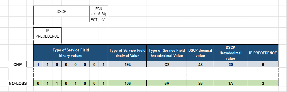
- RoCE traffic tagged with DSCP 26 on PRIORITY 3
- RoCE CNP traffic tagged with DSCP 48 and PRIORITY 7
Mapping Broadcom and logical interface names to configure DCQN-ECN/PFC and TOS/DSCP for RDMA Traffic attributes in AMD servers
DCQCN ECN, PFC and traffic marking need to be configured on the interfaces connected to the GPU backend; that is on the gpu#_eth (#=0-7) interfaces only.
In the Changing NIC attributes section of this document, we determined that the gpu#_eth interfaces in our servers, are Broadcom BCM957608 (shown below) NICs.
-
root@MI300X-01:/home/jnpr/SCRIPTS# cat devnames | grep gpu

gpu0_eth:Broadcom Inc. and subsidiaries BCM957608 25Gb/50Gb/100Gb/200Gb/400Gb Ethernet (rev 11)

gpu1_eth:Broadcom Inc. and subsidiaries BCM957608 25Gb/50Gb/100Gb/200Gb/400Gb Ethernet (rev 11)

gpu2_eth:Broadcom Inc. and subsidiaries BCM957608 25Gb/50Gb/100Gb/200Gb/400Gb Ethernet (rev 11)

gpu3_eth:Broadcom Inc. and subsidiaries BCM957608 25Gb/50Gb/100Gb/200Gb/400Gb Ethernet (rev 11)

gpu4_eth:Broadcom Inc. and subsidiaries BCM957608 25Gb/50Gb/100Gb/200Gb/400Gb Ethernet (rev 11)

gpu5_eth:Broadcom Inc. and subsidiaries BCM957608 25Gb/50Gb/100Gb/200Gb/400Gb Ethernet (rev 11)

gpu6_eth:Broadcom Inc. and subsidiaries BCM957608 25Gb/50Gb/100Gb/200Gb/400Gb Ethernet (rev 11)

gpu7_eth:Broadcom Inc. and subsidiaries BCM957608 25Gb/50Gb/100Gb/200Gb/400Gb Ethernet (rev 11)
All the steps for configuring Class of Service in this section will be focused on these Broadcom interfaces.
We will be using a combination of Linux system commands and Broadcom tools to enable, tune and monitor DCQCN ECN/PFC operation and RoCE traffic marking. For some of these commands we will need to find the Broadcom interface name associated with each gpu interface. Follow these steps to find these mappings:
- Find the PCI address of each gpu#_eth interface using the
following logic:
-
for iface in $(ls /sys/class/net | grep -E 'gpu[0-9]+_eth'); do

    pci_addr=$(readlink -f /sys/class/net/$iface/device | awk -F '/' '{print $NF}')

    echo "$iface => $pci_addr"

done1
EXAMPLE:
-
root@MI300X-01:/home/jnpr/SCRIPTS# for iface in $(ls /sys/class/net | grep -E 'gpu[0-9]+_eth'); do

    pci_addr=$(readlink -f /sys/class/net/$iface/device | awk -F '/' '{print $NF}')

    echo "$iface => $pci_addr"

done

gpu0_eth => 0000:06:00.0

gpu1_eth => 0000:23:00.0

gpu2_eth => 0000:43:00.0

gpu3_eth => 0000:66:00.0

gpu4_eth => 0000:86:00.0

gpu5_eth => 0000:a3:00.0

gpu6_eth => 0000:c3:00.0

gpu7_eth => 0000:e6:00.0
-
- Find the bnxt_re# (#=0-7) devices that corresponds to each PCI
address using the following logic:
-
for pci in $(find /sys/class/infiniband -type l -exec basename {} \;); do

    pci_addr=$(readlink -f /sys/class/infiniband/$pci/device | awk -F '/' '{print $NF}')

    echo "$pci => $pci_addr" |grep bnxt

done
EXAMPLE:
-
root@MI300X-01:/home/jnpr/SCRIPTS# for pci in $(find /sys/class/infiniband -type l -exec basename {} \;); do

    pci_addr=$(readlink -f /sys/class/infiniband/$pci/device | awk -F '/' '{print $NF}')

    echo "$pci => $pci_addr" |grep bnxt

done

bnxt_re5 => 0000:a3:00.0

bnxt_re3 => 0000:66:00.0

bnxt_re1 => 0000:23:00.0

bnxt_re6 => 0000:c3:00.0

bnxt_re4 => 0000:86:00.0

bnxt_re2 => 0000:43:00.0

bnxt_re0 => 0000:06:00.0

bnxt_re7 => 0000:e6:00.0
-
- MAP the GPU interface bnxt_re# or mlx5_# interface names.
Combine the outputs from steps 1 and 2 to create a full mapping from gpu#_eth to bnxt_re# or mlx5_#. You can see from the outputs that for example gpu0_eth corresponds to bnxt_re3 (0000:66:00.0)
You can use the following logic to simplify the process:
-
echo "GPU-to-NIC Mapping:"

for iface in $(ls /sys/class/net | grep -E 'gpu[0-9]+_eth'); do

    pci_addr=$(readlink -f /sys/class/net/$iface/device | awk -F '/' '{print $NF}')

    rdma_dev=$(find /sys/class/infiniband -type l -exec basename {} \; | while read rdma; do

        rdma_pci=$(readlink -f /sys/class/infiniband/$rdma/device | awk -F '/' '{print $NF}')

        if [[ "$pci_addr" == "$rdma_pci" ]]; then echo "$rdma"; fi

    done)

    echo "$iface => $pci_addr => $rdma_dev"

done
EXAMPLE:
-
root@MI300X-01:/home/jnpr/SCRIPTS# echo "GPU-to-NIC Mapping:"

for iface in $(ls /sys/class/net | grep -E 'gpu[0-9]+_eth'); do

    pci_addr=$(readlink -f /sys/class/net/$iface/device | awk -F '/' '{print $NF}')

    rdma_dev=$(find /sys/class/infiniband -type l -exec basename {} \; | while read rdma; do

        rdma_pci=$(readlink -f /sys/class/infiniband/$rdma/device | awk -F '/' '{print $NF}')

        if [[ "$pci_addr" == "$rdma_pci" ]]; then echo "$rdma"; fi

    done)

    echo "$iface => $pci_addr => $rdma_dev"

done

GPU-to-NIC Mapping:

gpu0_eth => 0000:06:00.0 => bnxt_re0

gpu1_eth => 0000:23:00.0 => bnxt_re1

gpu2_eth => 0000:43:00.0 => bnxt_re2

gpu3_eth => 0000:66:00.0 => bnxt_re3

gpu4_eth => 0000:86:00.0 => bnxt_re4

gpu5_eth => 0000:a3:00.0 => bnxt_re5

gpu6_eth => 0000:c3:00.0 => bnxt_re6

gpu7_eth => 0000:e6:00.0 => bnxt_re7
Configuring DCQN-ECN/PFC and TOS/DSCP for RDMA Traffic attributes in AMD servers (Broadcom interfaces)
Some of the parameters related to DCQN-ECN/PFC and TOS/DSCP are listed in the following table:
Table 25. Server DCQCN configuration parameters
| PARAMETER | DESCRIPTION | DEFAULT |
|---|---|---|
| cc_mode | 1 | |
| cnp_ecn | Enables/disables ECN | 0x1 (enabled) |
| cnp_dscp | DSCP value for RoCE congestion notification packets | 48 |
| cnp_prio | Priority for RoCE congestion notification packets | 7 |
| cnp_ratio_th | Defines the threshold ratio for generating CNPs. It determines the rate CNPs are sent in response to congestion, helping control the feedback mechanism's aggressiveness. | 0x0 |
| ecn_enable | Enable congestion control. | 0x1 (enabled) |
| ecn_marking | Enables tagging of packets as ECN-enabled. ECN = 01 | 0x1 (enabled) |
| default_roce_mode | Sets the default RoCE mode for RDMA | RoCE v2 |
| default_roce_tos | Sets the default ToS value for RDMA traffic | 104 |
| roce_dscp | DSCP value for RoCE packets. | 26 |
| roce_prio | Priority for RoCE packets. | 3 |
| rtt | Time period (µs) over which cnp and transmitted packets counts accumulate. At the end of rtt, the ratio between CNPs and TxPkts is computed, and the CP is updated. | 40 μs. |
BCM95741X Ethernet network adapters support three transmit and receive queues for each Ethernet port: 0, 4, and 5.
BCM95750X Ethernet network adapters support eight transmit and receive queues for each Ethernet port: 0 through 7.
By default, all queues are configured for weighted-fair-queueing (WFQ), with priority 0 traffic mapped to queue 4.
When the RoCE bnxt_re driver is loaded, CoSQ 0 is configured for lossless traffic, and CoSQ 5 is changed from WFQ to strict priority (SP) for CNP processing.
RoCE and CNP traffic can be tagged with different DSCP values or use VLAN tags instead.
By default, the ToS field is set to 104, which means DSCP is set to 48, and the ECN bits are set to 10 (ECN-enabled).
These parameters can be adjusted using three different methods:
- Configuring DCQCN/RDMA marking values directly
- Configuring DCQCN/RDMA marking values using Broadcom tools such
as
niccli,orlldptooldirectly - Configuring DCQCN/RDMA marking values using
thebnxt_setupcc.shutility, which uses eitherniccliorlldptool(default) behind the scenes.
The following sections describe the steps to make changes using these different options.
-
set class-of-service classifiers dscp mydscp forwarding-class CNP loss-priority low code-points 110000

set class-of-service classifiers dscp mydscp forwarding-class NO-LOSS loss-priority low code-points 011010

set class-of-service forwarding-classes class NO-LOSS pfc-priority 3
Configuring DCQN-ECN/PFC and TOS/DSCP for RDMA Traffic attributes directly
You can make changes to the DCQCN and traffic marking by directly editing the files that contain the values of each parameter. This method is the easiest and does not require installation of any additional tools. However, it is not an option for PFC related parameters, nor is it supported on all types of network adapters.
To complete these changes for a specific interface, you must be under in the proper interface directory, following these steps:
- Create interface directories for qos related values
We determined the mappings between the gpu#_eth interfaces and the corresponding Broadcom interface names
GPU-to-NIC Mapping:
gpu0_eth => 0000:06:00.0 => bnxt_re0
gpu1_eth => 0000:23:00.0 => bnxt_re1
gpu2_eth => 0000:43:00.0 => bnxt_re2
gpu3_eth => 0000:66:00.0 => bnxt_re3
gpu4_eth => 0000:86:00.0 => bnxt_re4
gpu5_eth => 0000:a3:00.0 => bnxt_re5
gpu6_eth => 0000:c3:00.0 => bnxt_re6
gpu7_eth => 0000:e6:00.0 => bnxt_re7
We will use the Broadcom interface names to create the directories (rdma_cm and bnxt_re) where the DCQCN attributes as well as other parameters and statistics will be located for each interface.
The interface specific directories do not exist until created using the following commands:
-
cd /sys/kernel/config

mkdir -p /rdma_cm/<Broadcom-interface-name>

mkdir -p /bnxt_re/<Broadcom-interface-name>
Notice that these two directories must be present.
-
root@MI300X-01:/# cd /sys/kernel/config/ls

bnxt_re  rdma_cm
If the rdma_cm directory for example is missing, try the following:
-
root@MI300X-01:/sys/kernel/config# sudo modprobe rdma_cm


root@MI300X-01:/sys/kernel/config# lsmod | grep rdma_cm

rdma_cm               147456  0

iw_cm                  61440  1 rdma_cm

ib_cm                 151552  1 rdma_cm

ib_core               507904  6 rdma_cm,iw_cm,bnxt_re,ib_uverbs,mlx5_ib,ib_cm
EXAMPLE:
-
root@MI300X-01:/# cd /sys/kernel/config/bnxt_re

root@MI300X-01:/sys/kernel/config/bnxt_re#

(NO FILES LISTED)

root@MI300X-01:/# cd /sys/kernel/config/rdma_cm

root@MI300X-01:/sys/kernel/config/rdma_cm# ls

(NO FILES LISTED)


root@MI300X-01:/sys/kernel/config# mkdir -p rdma_cm/bnxt_re0

root@MI300X-01:/sys/kernel/config# mkdir -p bnxt_re/bnxt_re0

root@MI300X-01:/sys/kernel/config# ls rdma_cm

bnxt_re0

root@MI300X-01:/sys/kernel/config# ls bnxt_re

bnxt_re0

root@MI300X-01:/sys/kernel/config# mkdir -p rdma_cm/bnxt_re1

root@MI300X-01:/sys/kernel/config# mkdir -p bnxt_re/bnxt_re1

root@MI300X-01:/sys/kernel/config# ls rdma_cm

bnxt_re0 bnxt_re1

root@MI300X-01:/sys/kernel/config# ls bnxt_re

bnxt_re0 bnxt_re1
Repeat these steps for all the gpu interfaces.
NOTE: You must be a root user to make these changes.-
jnpr@MI300X-01:/sys/kernel/config/bnxt_re/bnxt_re0/ports/1/cc$ sudo echo -n 0x1 > ecn_enable

-bash: ecn_enable: Permission denied.

jnpr@MI300X-01:/sys/kernel/config/bnxt_re/bnxt_re0/ports/1/cc$ sudo bash

root@MI300X-01:/sys/kernel/config/bnxt_re/bnxt_re0/ports/1/cc# sudo echo -n 0x1 > ecn_enable

root@MI300X-01:/sys/kernel/config/bnxt_re/bnxt_re0/ports/1/cc#
The new directories will contain values pertaining to ECN, ROCE traffic, and other functions:
-
root@MI300X-01:/sys/kernel/config# cd rdma_cm/bnxt_re0/ports/1

root@MI300X-01:/sys/kernel/config/rdma_cm/bnxt_re0/ports/1# ls

default_roce_mode  default_roce_tos

root@MI300X-01:/sys/kernel/config/rdma_cm/bnxt_re0/ports/1# cd /sys/kernel/config/bnxt_re/bnxt_re0/ports/1

root@MI300X-02:/sys/kernel/config/bnxt_re/bnxt_re0/ports/1$ ls

cc  tunables

root@MI300X-02:/sys/kernel/config/bnxt_re/bnxt_re0/ports/1$ ls tunables

acc_tx_path     cq_coal_en_ring_idle_mode       dbr_pacing_algo_threshold

en_qp_dbg       snapdump_dbg_lvl        user_dbr_drop_recov_timeout

cq_coal_buf_maxtime     cq_coal_normal_maxbuf           dbr_pacing_enable

gsi_qp_mode     stats_query_sec cq_coal_during_maxbuf

dbr_def_do_pacing       dbr_pacing_time min_tx_depth

user_dbr_drop_recov

root@MI300X-01:/sys/kernel/config/bnxt_re/bnxt_re0/ports/1/# ls cc

abs_max_quota   act_cr_factor   act_rel_cr_th   actual_cr_shift_correction_en

advanced        ai_rate_incr    ai_rtt_th1      ai_rtt_th2

apply   bw_avg_weight   cc_ack_bytes    cc_mode

cf_rtt_th       cnp_dscp        cnp_ecn cnp_prio

cnp_ratio_th    cp_bias cp_bias_en      cp_exp_update_th

cr_min_th       cr_prob_fac     cr_width        disable_prio_vlan_tx

ecn_enable      ecn_marking     exp_ai_rtts     exp_crcp_ratio

fair_cr_th      fr_num_rtts     g       inact_th

init_cp init_cr init_tr l64B_per_rtt

lbytes_per_usec max_cp_cr_th    max_quota       min_quota

min_time_bet_cnp        random_no_red_en        red_div red_rel_rtts_th

reduce_cf_rtt_th        reset_cc_cr_th  roce_dscp       roce_prio

rt_en   rtt     rtt_jitter_en   sc_cr_th1

sc_cr_th2       tr_lb   tr_prob_fac     tr_update_cyls

tr_update_mode
You can find a description of some of these parameters, as well as their current value using
cat to applywithin the/sys/kernel/config/bnxt_re/bnxt_re0/ports/1/cc#directory.EXAMPLE:
-
root@MI300X-01:/sys/kernel/config/bnxt_re/bnxt_re0/ports/1/cc# cat apply

ecn status (ecn_enable)                                 : Enabled

ecn marking (ecn_marking)                               : ECT(1)

congestion control mode (cc_mode)                       : DCQCN-P

send priority vlan (VLAN 0)                             : Disabled

running avg. weight(g)                                  : 8

inactivity threshold (inact_th)                         : 10000 usec

initial current rate (init_cr)                          : 0xc8

initial target rate (init_tr)                           : 0x320

cnp header ecn status (cnp_ecn)                         : ECT(1)

rtt jitter (rtt_jitter_en)                              : Enabled

link bytes per usec (lbytes_per_usec)                   : 0x7fff byte/usec

current rate width (cr_width)                           : 0xe bits

minimum quota period (min_quota)                        : 0x4

maximum quota period (max_quota)                        : 0x7

absolute maximum quota period(abs_max_quota)            : 0xff

64B transmitted in one rtt (l64B_per_rtt)               : 0xf460

roce prio (roce_prio)                                   : 3

roce dscp (roce_dscp)                                   : 26

cnp prio (cnp_prio)                                     : 7

cnp dscp (cnp_dscp)                                     : 48
-
- Enable RoCEv2 operation.
Even though RoCEv2 should be the default mode, the command to enable RoCEv2 is shown here.
NOTE: This change is made under the rdma_cm directory-
root@MI300X-01:/# cd /sys/kernel/config/rdma_cm/bnxt_re0/ports/1

root@MI300X-01:/sys/kernel/config/rdma_cm/bnxt_re0/ports/1# ls

default_roce_mode  default_roce_tos

root@MI300X-01:/sys/kernel/config/rdma_cm/bnxt_re0/ports/1# echo RoCE v2 > default_roce_mode
NOTE: Enter the value exactly as shown, including the space: “RoCE v2” (case sensitive).After setting the parameter, apply the new values as follows:
-
echo -n 0x1 > apply
Verify the changes:
-
root@MI300X-01:/sys/kernel/config/rdma_cm/bnxt_re1/ports/1# cat default_roce_mode

RoCE v2
-
-
Enable ECN response and notification functions.
Even though ECN should be enabled by default, the command to enable ECN is shown here.root@MI300X-01:/# cd /sys/kernel/config/bnxt_re/bnxt_re0/ports/1/cc
-
root@MI300X-01:/sys/kernel/config/bnxt_re/bnxt_re0/ports/1/cc# echo -n 0x1 > ecn_enable
echo -n 0x0
> ecn_enable
-
root@MI300X-01:/sys/kernel/config/bnxt_re/bnxt_re0/ports/1/cc# echo -n 0x1 > ecn_enable
When ECN is enabled on the Broadcom interfaces, they will respond to CNP packets (RP) and will generate CNP packets when ECN-marked are received (NP).
To disable it, enter echo -n 0x0 > cnp_ecn
instead.
After setting the parameter, apply the new values:
-
echo -n 0x1 > apply
Verify the changes:
-
root@MI300X-01:/sys/kernel/config/bnxt_re/bnxt_re0/ports/1/cc# cat ecn_enable

0x1
You can also enable the marking of both CNP and ROCE packets as ECN-eligible (meaning; these packets can be marked across the network when congestion occurs).
-
root@MI300X-01:/sys/kernel/config/bnxt_re/bnxt_re0/ports/1/cc# cat cnp_ecn

0x1
To summarize these attributes:
| ecn_enable | Enables/Disables the RP (response point) side of ECN. It enables the device to respond to CNP packets. Default = 1 (enable) |
| cnp_ecn | Configures marking CNP packets as ECN-eligible. Either a value of 01 or 10 for ECT field. |
| ecn_marking | Configures marking ROCE packets as ECN-eligible. Either a value of 01 or 10 for ECT field. |
- Configure the DSCP and PRIO values
for CNP and RoCEv2 packets.
NOTE: Configuring these values manually, as shown below, is not an option for all types of Broadcom interface cards. For example, for BCM95741X devices you can use this method to configure the ECN, and RoCE priority values but on the BCM95750X/BCM957608 devices you can configure
roce_dscp,
ecn_dscp
See Broadcom Ethernet Network Adapter Congestion Control Parameters
-
root@MI300X-01:/sys/kernel/config/bnxt_re/bnxt_re0/ports/1/cc#

echo -n 0x30 > cnp_dscp

# DSCP value as 48 (30 in HEX)
NOTE: These changes are made under the bnxt_re0 directory.-
echo -n 0x1a > roce_dscp

# DSCP value as 26 (1a in HEX)

echo -n 0x7 > cnp_prio

echo -n 0x3 > roce_prio
NOTE: The following error indicates that changing the value of this parameter directly is not supported. In the case of BCM957608 roce_prio, and cnp_prio need to be configured usingbnxt_setupcc.sh(described later).-
root@MI300X-01:/sys/kernel/config/bnxt_re/bnxt_re0/ports/1/cc# echo -n 0x3 > roce_prio

bash: echo: write error: Invalid argument
After setting the parameter, apply the new values:
-
echo -n 0x1 > apply
Verify the changes:
-
root@MI300X-01:/sys/kernel/config/bnxt_re/bnxt_re0/ports/1/cc# cat cnp_dscp

0x30

root@MI300X-01:/sys/kernel/config/bnxt_re/bnxt_re0/ports/1/cc# cat cnp_dscp

0x1a


root@MI300X-01:/sys/kernel/config/bnxt_re/bnxt_re0/ports/1/cc# cat cnp_prio

0x7

root@MI300X-01:/sys/kernel/config/bnxt_re/bnxt_re0/ports/1/cc# cat cnp_prio

0x3
-
- Configure the DCQCN algorithm (under the bnxt_re directory).
The default DCQCN Congestion Control (cc-mode) algorithm in Broadcom Ethernet network adapter is DCQCN-P. The mode can be changed using these commands:
NOTE: This change is made under the bnxt_re0 directory.To use DCQCN-P configure:
-
cd /sys/kernel/config/bnxt_re/bnxt_re0/ports/1/cc/

echo -n 1 > cc_mode

echo -n 1 > apply

cat apply
To use DCQCN-D configure:
-
root@MI300X-01:/

cd /sys/kernel/config/bnxt_re/bnxt_re0/ports/1/cc/

echo -n 0 > cc_mode

echo -n 1 > apply
-
- Check all the attributes that were configured.
The following command shows all the interface parameters:
-
root@MI300X-01:/

cd /sys/kernel/config/bnxt_re/bnxt_re0/ports/1/cc/

echo -n 1 > advanced

echo -n 1 > apply

cat apply
For more information on the DCQCN algorithm in Broadcom Ethernet network adapter check the following documents: Changing Congestion Control Mode Settings and RoCE Congestion Control
EXAMPLE:
We have highlighted some ECN/CNP related parameters:
-
root@MI300X-01:/sys/kernel/config#

cd /sys/kernel/config/bnxt_re/bnxt_re0/ports/1/cc/

echo -n 1 > advanced

echo -n 1 > apply

cat apply

ecn status (cnp_ecn)                                    : Enabled
              ecn marking (ecn_marking)                               : ECT(1)
              congestion control mode (cc_mode)                       : DCQCN-P

send priority vlan (VLAN 0)                             : Disabled

running avg. weight(g)                                  : 8

inactivity threshold (inact_th)                         : 10000 usec

initial current rate (init_cr)                          : 0xc8

initial target rate (init_tr)                           : 0x320

round trip time (rtt)                                   : 45 usec

cnp header ecn status (cnp_ecn)                         : ECT(1)

rtt jitter (rtt_jitter_en)                              : Enabled

link bytes per usec (lbytes_per_usec)                   : 0x7fff byte/usec

current rate width (cr_width)                           : 0xe bits

minimum quota period (min_quota)                        : 0x4

maximum quota period (max_quota)                        : 0x7

absolute maximum quota period(abs_max_quota)            : 0xff

64B transmitted in one rtt (l64B_per_rtt)               : 0xf460

minimum time between cnps (min_time_bet_cnp)            : 0x0 usec

initial congestion probability (init_cp)                : 0x3ff

target rate update mode (tr_update_mode)                : 1

target rate update cycle (tr_update_cyls)               : 0x0

fast recovery rtt (fr_num_rtts)                         : 0x5 rtts

active increase time quanta (ai_rate_incr)              : 0x1

reduc. relax rtt threshold (red_rel_rtts_th)            : 0x2 rtts

additional relax cr rtt (act_rel_cr_th)                 : 0x50 rtts

minimum current rate threshold (cr_min_th)              : 0x0

bandwidth weight (bw_avg_weight)                        : 0x5

actual current rate factor (act_cr_factor)              : 0x0

current rate level to max cp (max_cp_cr_th)             : 0x3ff

cp bias state (cp_bias_en)                              : Disabled

log of cr fraction added to cp (cp_bias)                : 0x3

cr threshold to reset cc (reset_cc_cr_th)               : 0x32a

target rate lower bound (tr_lb)                         : 0x1

current rate probability factor (cr_prob_fac)           : 0x3

target rate probability factor (tr_prob_fac)            : 0x5

current rate fairness threshold (fair_cr_th)            : 0x64

reduction divider (red_div)                             : 0x1

rate reduction threshold (cnp_ratio_th)                 : 0x0 cnps

extended no congestion rtts (exp_ai_rtts)               : 0x8 rtt

log of cp to cr ratio (exp_crcp_ratio)                  : 0x7

use lower rate table entries (rt_en)                    : Disabled

rtts to start cp track cr (cp_exp_update_th)            : 0x1a4 rtt

first threshold to rise ai (ai_rtt_th1)                 : 0x40 rtt

second threshold to rise ai (ai_rtt_th2)                : 0x80 rtt

actual rate base reduction threshold (cf_rtt_th)        : 0x15e rtt

first severe cong. cr threshold (sc_cr_th1)             : 0x0

second severe cong. cr threshold (sc_cr_th2)            : 0x0

cc ack bytes (cc_ack_bytes)                             : 0x44

reduce to init rtts threshold(reduce_cf_rtt_th)         : 0x3eb rtt

random no reduction of cr (random_no_red_en)            : Enabled

actual cr shift correction (actual_cr_shift_correction_en)              : Enabled

roce prio (roce_prio)                                   : 3

roce dscp (roce_dscp)                                   : 26

cnp prio (cnp_prio)                                     : 7
              cnp dscp (cnp_dscp)                                     : 0
Configuring DCQN-ECN/PFC and TOS/DSCP for RDMA Traffic attributes using niccli
You can make changes to the DCQCN and traffic marking using the NICCLI Configuration Utility.
niccli is a management tool for Broadcom Ethernet
network adapters that provides detailed information, including
type, status, serial number, and firmware version. It also enables
the configuration of interface attributes such as DCQCN-ECN, PFC,
and TOS/DSCP for optimizing RDMA traffic.
Installing the NICCLI Configuration Utility
-
root@MI300X-01:/$ which niccli

/usr/bin/niccli

root@MI300X-01:/usr/bin$ ls niccli -l

lrwxrwxrwx 1 18896 1381 18 Sep 25 18:52 niccli -> /opt/niccli/niccli
You can obtain a summary of the interface adapters and ethernet
ports that can be managed with niccli present on the server using
niccli listdev, or list-eth as shown in the example
below.
-
root@MI300X-01:/home/jnpr# niccli --listdev

1 ) Supermicro PCIe 400Gb Single port QSFP56-DD Ethernet Controller (Adp#1 Port#1)

     Device Interface Name     : gpu0_eth

     MAC Address               : 7C:C2:55:BD:75:D0

     PCI Address               : 0000:06:00.0

2 ) Supermicro PCIe 400Gb Single port QSFP56-DD Ethernet Controller (Adp#2 Port#1)

     Device Interface Name     : gpu1_eth

     MAC Address               : 7C:C2:55:BD:79:20

     PCI Address               : 0000:23:00.0

3 ) Supermicro PCIe 400Gb Single port QSFP56-DD Ethernet Controller (Adp#3 Port#1)

     Device Interface Name     : gpu2_eth

     MAC Address               : 7C:C2:55:BD:7D:F0

     PCI Address               : 0000:43:00.0

4 ) Supermicro PCIe 400Gb Single port QSFP56-DD Ethernet Controller (Adp#4 Port#1)

     Device Interface Name     : gpu3_eth

     MAC Address               : 7C:C2:55:BD:7E:20

     PCI Address               : 0000:66:00.0

5 ) Supermicro PCIe 400Gb Single port QSFP56-DD Ethernet Controller (Adp#5 Port#1)

     Device Interface Name     : gpu4_eth

     MAC Address               : 7C:C2:55:BD:75:10

     PCI Address               : 0000:86:00.0

6 ) Supermicro PCIe 400Gb Single port QSFP56-DD Ethernet Controller (Adp#6 Port#1)

     Device Interface Name     : gpu5_eth

     MAC Address               : 7C:C2:55:BD:7D:C0

     PCI Address               : 0000:A3:00.0

7 ) Supermicro PCIe 400Gb Single port QSFP56-DD Ethernet Controller (Adp#7 Port#1)

     Device Interface Name     : gpu6_eth

     MAC Address               : 7C:C2:55:BD:84:90

     PCI Address               : 0000:C3:00.0

8 ) Supermicro PCIe 400Gb Single port QSFP56-DD Ethernet Controller (Adp#8 Port#1)

     Device Interface Name     : gpu7_eth

     MAC Address               : 7C:C2:55:BD:83:10

     PCI Address               : 0000:E6:00.0

root@MI300X-01:/home/jnpr# niccli --list-eth

     BoardId      Interface       PCIAddr

  1) BCM957608     gpu0_eth        0000:06:00.0

  2) BCM957608     gpu1_eth        0000:23:00.0

  3) BCM957608     gpu2_eth        0000:43:00.0

  4) BCM957608     gpu3_eth        0000:66:00.0

  5) BCM957608     gpu4_eth        0000:86:00.0

  6) BCM957608     gpu5_eth        0000:A3:00.0

  7) BCM957608     gpu6_eth        0000:C3:00.0

  8) BCM957608     gpu7_eth        0000:E6:00.0
You can use niccli in either oneline
mode, interactive mode, or batch
mode. The niccli -h help provides a
high-level description of these modes. In this section, we will
show some examples of how to use the oneline and
interactive modes for DCQCN-ECN, PFC, and TOS/DSCP
configuration.
-
root@MI300X-01:/sys/kernel/config/bnxt_re/bnxt_re0/ports/1/cc# niccli --help

-------------------------------------------------------------------------------

NIC CLI v231.2.63.0 - Broadcom Inc. (c) 2024 (Bld-94.52.34.117.16.0)

-------------------------------------------------------------------------------

NIC CLI - Help Option

--help / -h Displays the following help page.

Utility provides three modes of execution,

     1. Interactive Mode

         To launch in interactive mode :

             <NIC CLI executable> [-i <index of the target>] | -pci <NIC pci address>

         After launching in interactive mode, execute 'help' command to

         display the list of available commands.

     2. Oneline Mode

         To launch in Oneline mode :

             <NIC CLI executable> [-i <index of the target>] | -pci <NIC pci address> <command>

         To list available commands in Oneline mode :

             <NIC CLI executable> [-i <index of the target>] | -pci <NIC pci address> help

         Legacy Nic command syntax :

         To launch in Oneline mode :

             <NIC CLI executable> [-dev [<index of the target> | <mac addr> | <NIC pci address>]] <command>

         To list available commands in Oneline mode :

             <NIC CLI executable> [-dev [<index of the target> | <mac addr> | <NIC pci address>]] help

     3. Batch Mode

         To launch in batch mode :

             <NIC CLI executable> [-i <index of the target>] | -pci <NIC pci address> --batch <batch file>

         NOTE: Batch mode requires flat text file with utility supported commands.

         Commands have to be provided in ascii format with the valid parameters.

         Supported commands can be listed using One-Line mode or Interactive mode

         Upon failure of any commands, utility will exit without continuing with other commands

List available targets for Oneline or Batch mode

     <NIC CLI executable> --list

     <NIC CLI executable> --listdev
Entering
niccli with no options allows you to work in the
interactive mode, where you select an adapter/interface (by index)
and then the proper <command> (e.g., show,
get_qos, set_map) to obtain information or make changes to the
selected interface.
You can identify the interface index corresponding to each
interface using the method described in the Mapping Broadcom interface
name with logical interface name section. This will give you
the mappings between interfaces and pcie address which you can then
correlate with the output of niccli below.
Once identified, enter the interface index (first column in the output) as shown in the example below.
EXAMPLE:
-
root@MI300X-01:/sys/kernel/config/bnxt_re/bnxt_re0/ports/1/cc# niccli ------------------------------------------------------------------------------- NIC CLI v231.2.63.0 - Broadcom Inc. (c) 2024 (Bld-94.52.34.117.16.0) ------------------------------------------------------------------------------ BoardId MAC Address FwVersion PCIAddr Type Mode 1) BCM957608 7C:C2:55:BD:75:D0 230.2.49.0 0000:06:00.0 NIC PCI 2) BCM957608 7C:C2:55:BD:79:20 230.2.49.0 0000:23:00.0 NIC PCI 3) BCM957608 7C:C2:55:BD:7D:F0 230.2.49.0 0000:43:00.0 NIC PCI 4) BCM957608 7C:C2:55:BD:7E:20 230.2.49.0 0000:66:00.0 NIC PCI 5) BCM957608 7C:C2:55:BD:75:10 230.2.49.0 0000:86:00.0 NIC PCI 6) BCM957608 7C:C2:55:BD:7D:C0 230.2.49.0 0000:A3:00.0 NIC PCI 7) BCM957608 7C:C2:55:BD:84:90 230.2.49.0 0000:C3:00.0 NIC PCI 8) BCM957608 7C:C2:55:BD:83:10 230.2.49.0 0000:E6:00.0 NIC PCI Enter the target index to connect with : 1 BCM957608> Once you are at the prompt for the selected NIC, you can enter commands such asshow, device_health_check, listdev,andlisteth) BCM957608> show NIC State : Up Device Type : THOR2 PCI Vendor ID : 0x14E4 PCI Device ID : 0x1760 PCI Revision ID : 0x11 PCI Subsys Vendor ID : 0x15D9 PCI Subsys Device ID : 0x1D42 Device Interface Name : gpu0_eth MAC Address : 7C:C2:55:BD:75:D0 Base MAC Address : 7C:C2:55:BD:75:D0 Serial Number : OA248S074777 Part Number : AOC-S400G-B1C PCI Address : 0000:06:00.0 Chip Number : BCM957608 Chip Name : THOR2 Description : Supermicro PCIe 400Gb Single port QSFP56-DD Ethernet Controller ---more--- BCM957608> devid Device Interface Name : gpu0_eth PCI Vendor ID : 0x14E4 PCI Device ID : 0x1760 PCI Revision ID : 0x11 PCI Subsys Vendor ID : 0x15D9 PCI Subsys Device ID : 0x1D42 PCI Address : 0000:06:00.0 BCM957608> device_health_check Device Health Information : SBI Mismatch Check : OK SBI Booted Check : OK SRT Mismatch Check : OK SRT Booted Check : OK CRT Mismatch Check : OK CRT Booted Check : OK Second RT Image : CRT Image Second RT Image Redundancy : Good Image Fastbooted Check : OK Directory Header Booted Check : OK Directory Header Mismatch Check : OK MBR Corrupt Check : OK NVM Configuration : OK FRU Configuration : OK --------------------------------------------- Overall Device Health : Healthy BCM957608> devid Device Interface Name : gpu0_eth PCI Vendor ID : 0x14E4 PCI Device ID : 0x1760 PCI Revision ID : 0x11 PCI Subsys Vendor ID : 0x15D9 PCI Subsys Device ID : 0x1D42 PCI Address : 0000:06:00.0
niccli -i <interface-index>
<command>
niccli -list command can be used to
determine the interface index.EXAMPLE
-
root@MI300X-01:/sys/kernel/config/bnxt_re/bnxt_re0/ports/1/cc# niccli --list

-------------------------------------------------------------------------------

NIC CLI v231.2.63.0 - Broadcom Inc. (c) 2024 (Bld-94.52.34.117.16.0)

-------------------------------------------------------------------------------

     BoardId     MAC Address        FwVersion    PCIAddr        Type   Mode

  1) BCM957608    7C:C2:55:BD:75:D0  230.2.49.0   0000:06:00.0   NIC    PCI

  2) BCM957608    7C:C2:55:BD:79:20  230.2.49.0   0000:23:00.0   NIC    PCI

  3) BCM957608    7C:C2:55:BD:7D:F0  230.2.49.0   0000:43:00.0   NIC    PCI

  4) BCM957608    7C:C2:55:BD:7E:20  230.2.49.0   0000:66:00.0   NIC    PCI

  5) BCM957608    7C:C2:55:BD:75:10  230.2.49.0   0000:86:00.0   NIC    PCI

  6) BCM957608    7C:C2:55:BD:7D:C0  230.2.49.0   0000:A3:00.0   NIC    PCI

  7) BCM957608    7C:C2:55:BD:84:90  230.2.49.0   0000:C3:00.0   NIC    PCI

  8) BCM957608    7C:C2:55:BD:83:10  230.2.49.0   0000:E6:00.0   NIC    PCI
The sudo niccli help provides an extensive list of
commands and options available for both interactive and one-line
mode.
-
root@MI300X-01:/home/jnpr# sudo niccli help

-------------------------------------------------------------------------------

NIC CLI v231.2.63.0 - Broadcom Inc. (c) 2024 (Bld-94.52.34.117.16.0)

-------------------------------------------------------------------------------

Commands sets - Generic/Offline

-------------------------------------------------------------------------------

list                      - Lists all the compatible devices

listdev                   - Lists all the compatible devices (NIC legacy syntax)

devid                     - Query Broadcom device id's.

pkgver                    - Display FW PKG version installed on the device.

verify                    - Verify FW packages & NVM

nvm-list                  - Display NVM components and its associated versions.

nvmview                   - View NVM directories data

list-eth                  - Lists all NIC devices with ethernet interface names

help                      - Lists the available commands

quit                      - Quits from the application

Commands for platform 'BCM57xxx Performance NIC' and interface 'Direct PCIe'

-------------------------------------------------------------------------------

show                      - Shows NIC specific device information

coredump                  - Retrieves coredump data from device.

snapdump                  - Retrieves snapdump data from device.

version                   - Display the current version of the application

txfir                     - Network Interface Card Transmission Finite

                          - Impulse Response

msixmv                    - Display and configure the number of MSIX max

                          - vectors values for VF's per each PF

scan                      - Scan PCI devices in the topology

pcie                      - Show/Execute pcie operation

nvm                       - NVRAM Option Management

pfalloc                   - Configure and Query for the number of PFs per PCIe

                          - endpoint

rfd                       - Restores NVM configuration to factory defaults

backuppowercfg            - Backup Power Configuration

tsio                      - TSIO function capability on the pin

ingressqos                - Query and configure the ingressqos parameters

egressqos                 - Query and configure the egressqos parameters

dutycycle                 - Set duty cycle on TSIO outgoing signal

dllsource                 - Set the DLL source for PHC

vf                        - Configure and Query for a trusted VF

rxportrlmt                - Configure the receive side port rate limit

rxrlmt                    - Query the configured receive side rate control parameters

rxeprlmt                  - Configure the receive side rate control parameters for a given endpoint

txpartitionrlmt           - Query and Configure the transmit side partition rate limit applies to traffic

                          - sent from a partition, which is one PF and all of its child VFs

txportrlmt                - Query and Configure the transmit side of port rate limit

txeprlmt                  - Query and Configure the PCIe endpoint transmit rate control

vf                        - Configure and Query for a trusted VF

pfc                       - Configure the priority-based flow control for a given priority

apptlv                    - Configure the priority for the AppTLV

tcrlmt                    - Configure the rate limit for each traffic class

ets                       - Configure the enhanced transmission selection, priority to traffic class and bandwidths

up2tc                     - Configure the user priorities to traffic classes

getqos                    - Query the configured enhanced transmission selection, priority to traffic class and bandwidths

listmap                   - List the priority to traffic class and queueid mapping

dscp2prio                 - Query the dscp to priority mapping

reset                     - Reset the device

synce                     - Configure the synchronous ethernet profile

dscdump                   - Retrieves dscdump for device

ptp                       - PTP extended parameters operation

prbs_test                 - Run PRBS loopback test

serdes                    - Plots the serdes pci and ethernet eye and prints the horizontal and vertical margin values


Legacy NVM commands :     - Query commands

---------------------     - ---------------

device_info               - Query Broadcom device information and default hardware

                          - resources profile version.

device_temperature        - Query the device temperature in Celsius.

get_backup_power_config   - Query backup power configuration of the device.

moduleinfo                - Query the PHY module information.

nvm_measurement           - Query the active NVM configuration.

get_ptp_extended          - Query the PTP extended parameters.

getoption                 - Query current NVM configuration option settings

                          - of a device.

pcie_counters             - Display the pcie counters.

saveoptions               - Save NVM configuration options on the device

                          - to a file.

get_sync_ethernet         - Get the synchronous ethernet frequency profile

get_txfir                 - Query the TX FIR settings.

cert_provision_state      - Query the imported certificate chain on the device.

read                      - Read the NVM item data and write its contents to a file.

mh_pf_alloc               - Query the number of PFs per PCIe endpoint.

                          - This command is supported only on Thor devices.

get_tsio_function_pin     - Query TSIO function capability on the pin.


Legacy NVM commands :     - Debug commands

---------------------     - ---------------

device_health_check       - Checks the device health.

backup                    - Backup NVM contents to a file


Legacy NVM commands :     - Configuration commands

---------------------     - ---------------

reset_ap                  - Reset management processor.

setoption                 - Configure NVM configuration option settings

                          -  of a device.

msix_max_vectors          - Configure the number of MSI-X max vectors per

                          - VF for each PF.

loopback                  - Query/perform loopback config.

add_ntuple_filter         - Add ntuple flow filter.

free_ntuple_filter        - Free ntuple flow filter.

cfgtunnel                 - query/config custom tunnel port/rss.

write                     - Create or overwrite NVM data item with a file.

set_txfir                 - Configures the TX FIR settings

set_ptp_extended          - Set PTP extended parameters

mh_pf_alloc               - Query/Configure the number of PFs per PCIe endpoint.

                          - This command is supported only on Thor devices.

restore_factory_defaults  - Restores NVM configuration to factory defaults

resmgmt                   - Query and Configure resources of the device.


Legacy NVM commands :     - FW update commands

---------------------     - ---------------

fw_sync                   - Synchronize primary & secondary FW images

livepatch                 - Query, Activate and Deactivate the patch in live

install                   - Install/Update FW


Legacy QoS Rx commands :  - Rx Qos commands

---------------------     - ---------------

rx_port_ratelimit         - The user can configure rx rate control that applies to all traffic in a rx CoS queue group.

rx_endpoint_ratelimit     - The user can configure endpoint rx rate control that applies to all traffic in a rx CoS queue group.

get_rx_ratelimits         - The user can query the rx rate limits.


Legacy QoS Tx commands :  - Tx Qos commands

---------------------     - ---------------

partition_tx_ratelimit    - This command is used to configure partition tx rate limit.

get_partition_tx_ratelimit - This command is used to query the partition rate limit configuration for a given partition.

get_tx_port_ratelimit     - This command is used to query the tx side of port rate limit.

tx_port_ratelimit         - This command is used to configure the tx side of port rate limit

tx_endpoint_ratelimit     - This command is used to configure PCIe endpoint tx rate limit.

get_tx_endpoint_ratelimits - This command is used to query the tx endpoint rate limits.


Legacy DCB commands :     - Data Center Bridging commands

---------------------     - ---------------

set_pfc                   - This command is used to enable PFC on a given priority

set_apptlv                - This command is used to configure the priority of the AppTLV.

ratelimit                 - This command is used to configure the rate limit for each traffic class.

set_ets                   - This command is used to configure the DCB parameters.

set_map                   - This command is used to configure the priority to traffic class.

get_qos                   - This command is used to query the DCB parameters.

dump                      - This command is used to dump the priority to cos mapping.

get_dscp2prio             - This command is used to query the dscp to priority mapping.
The following examples show you how to
use niccli to obtain information about a specific
interface.
- Check interface status.
The
niccli -i <interface> showprovides details about the interface such as type, MAC address, firmware, serial number, device health, temperature and so on.EXAMPLE:
-
root@MI300X-01:/sys/kernel/config/bnxt_re/bnxt_re0/ports/1/cc# sudo niccli -i 1 show

-------------------------------------------------------------------------------

NIC CLI v231.2.63.0 - Broadcom Inc. (c) 2024 (Bld-94.52.34.117.16.0)

-------------------------------------------------------------------------------

NIC State                           : Up

Device Type                         : THOR2

PCI Vendor ID                       : 0x14E4

PCI Device ID                       : 0x1760

PCI Revision ID                     : 0x11

PCI Subsys Vendor ID                : 0x15D9

PCI Subsys Device ID                : 0x1D42

Device Interface Name               : gpu0_eth

MAC Address                         : 7C:C2:55:BD:75:D0

Base MAC Address                    : 7C:C2:55:BD:75:D0

Serial Number                       : OA248S074777

Part Number                         : AOC-S400G-B1C

PCI Address                         : 0000:06:00.0

Chip Number                         : BCM957608

Chip Name                           : THOR2

Description                         : Supermicro PCIe 400Gb Single port QSFP56-DD Ethernet Controller

Firmware Name                       : PRIMATE_FW

Firmware Version                    : 230.2.49.0

RoCE Firmware Version               : 230.2.49.0

HWRM Interface Spec                 : 1.10.3

Kong mailbox channel                : Not Applicable

Active Package Version              : 230.2.52.0

Package Version on NVM              : 230.2.52.0

Active NVM config version           : 0.0.5

NVM config version                  : 0.0.5

Reboot Required                     : No

Firmware Reset Counter              : 0

Error Recovery Counter              : 0

Crash Dump Timestamp                : Not Available

Secure Boot                         : Enabled

Secure Firmware Update              : Enabled

FW Image Status                     : Operational

Crash Dump Available in DDR         : No

Device Temperature                  : 57 Celsius

PHY Temperature                     : Not Available

Optical Module Temperature          : 65 Celsius

Device Health                       : Good
-
- Check QoS settings
sudo niccli -i <interface-index> dscp2prio and
sudo niccli -i 1 listmap -pri2cos
-
root@MI300X-01:/home/jnpr# sudo niccli -i 1 dscp2prio

-------------------------------------------------------------------------------

NIC CLI v231.2.63.0 - Broadcom Inc. (c) 2024 (Bld-94.52.34.117.16.0)

-------------------------------------------------------------------------------

dscp2prio mapping:

          priority:7  dscp: 48

          priority:3  dscp: 26

root@MI300X-01:/home/jnpr# sudo niccli -i 2 listmap -pri2cos

-------------------------------------------------------------------------------

NIC CLI v231.2.63.0 - Broadcom Inc. (c) 2024 (Bld-94.52.34.117.16.0)

-------------------------------------------------------------------------------

Base Queue is 0 for port 0

----------------------------

Priority   TC   Queue ID

------------------------

 0         0    4

 1         0    4

 2         0    4

 3         1    0

 4         0    4

 5         0    4

 6         0    4

 7         2    5
The outputs in the example show the defaults for:
- Queues status. Only queues 0, 1, and 2 are enabled.
- Priority to DSCP mappings: priority 7 => DSCP 48 & priority 3 => DSCP 26.
- Priority to TC (traffic class) and queue mappings: priority 7 => TC2 (queue 0) => DSCP 48 & priority 3 => TC1 (queue 5) => DSCP 26.
The sudo niccli -i <interface-index> get_qos
command provides a summary of the QoS configuration on the
interface.
EXAMPLE:
-
root@MI300X-01:/sys/kernel/config/bnxt_re/bnxt_re0/ports/1/cc# sudo niccli -i 1 get_qos

-------------------------------------------------------------------------------

NIC CLI v231.2.63.0 - Broadcom Inc. (c) 2024 (Bld-94.52.34.117.16.0)

-------------------------------------------------------------------------------

IEEE 8021QAZ ETS Configuration TLV:

         PRIO_MAP: 0:0 1:0 2:0 3:1 4:0 5:0 6:0 7:2

         TC Bandwidth: 50% 50% 0%

         TSA_MAP: 0:ets 1:ets 2:strict

IEEE 8021QAZ PFC TLV:

         PFC enabled: 3

IEEE 8021QAZ APP TLV:

         APP#0:

          Priority: 7

          Sel: 5

          DSCP: 48

         APP#1:

          Priority: 3

          Sel: 5

          DSCP: 26

         APP#2:

          Priority: 3

          Sel: 3

          UDP or DCCP: 4791

TC Rate Limit: 100% 100% 100% 0% 0% 0% 0% 0%
| IEEE 802.1Qaz ETS Configuration TLV: shows the Enhanced Transmission Selection (ETS) configuration | |
|---|---|
| PRIO_MAP: 0:0 1:0 2:0 3:1 4:0 5:0 6:0 7:2 |
Maps priorities to Traffic Classes (TC) Priority 0, 1, 2, 4, 5, 6 → TC 0 Priority 3 → TC 1 Priority 7 → TC 2 |
| TC Bandwidth: 50% 50% 0% |
Allocates bandwidth percentages to traffic classes. TC 0: 50% of the total bandwidth. TC 1: 50%. TC 2: 0%. |
| TSA_MAP: 0:ets 1:ets 2:strict |
Together with TC Bandwidth, TSA_MAP allocates resources and defines service priority for each TC. Equivalent to schedulers & scheduler-map in Junos. Specifies the Transmission Selection Algorithm (TSA) used for each TC: TC 0 and TC 1 use ETS (Enhanced Transmission Selection) and share the available bandwidth 50/50 TC 2 uses strict priority, meaning TC 2 traffic will always be sent first |
| IEEE 802.1Qaz PFC TLV: defines traffic classification using the APP TLV (Type-Length-Value) format | |
| PFC enabled: 3 |
Indicates that PFC is enabled on priority 3. Other priorities do not have PFC enabled. PFC ensures that traffic with this priority can pause instead of being dropped during congestion. |
| IEEE 802.1Qaz APP TLV | |
|
APP#0: Priority: 7 Sel: 5 DSCP: 48 APP#1: Priority: 3 Sel: 5 DSCP: 26 APP#2: Priority: 3 Sel: 3 UDP or DCCP: 4791 |
Maps traffic to Traffic Classes. Equivalent to multifield classifiers in Junos. APP#0: Traffic marked with DSCP = 48 is mapped to priority 7 APP#1: Traffic marked with DSCP = 48 is mapped to priority 3 APP#2: UDP or DCCP traffic with port = 4791 (RoCEv2) is mapped to priority 3 |
| TC Rate Limit: 100% 100% 100% 0% 0% 0% 0% 0% |
TC 0, TC 1, and TC 2 can use up to 100% of the bandwidth allocated to them. TC 3 through TC 7 are set to 0%, meaning they are not currently configured to transmit traffic. |
If needed, change the priority to traffic class mappings or the applications to traffic class mappings.
We recommend keeping the default settings and making sure they are consistent with the class-of-service configuration on the leaf nodes in the GPU backend fabric.
-
[edit class-of-service classifiers]

jnpr@gpu-backend-rack1-001-leaf1# show

dscp mydscp {

    forwarding-class CNP {

        loss-priority low code-points 110000;  <= DSCP = 48

    }

    forwarding-class NO-LOSS {

        loss-priority low code-points 011010;  <= DSCP = 26

    }

 }

}

[edit class-of-service forwarding-classes]

jnpr@gpu-backend-rack1-001-leaf1# show

class CNP queue-num 3;

class NO-LOSS queue-num 4 no-loss pfc-priority 3;
If there are any requirements to change the priority to traffic class mappings or the applications to traffic class mappings the following commands can be used:
Priority to traffic class mappings
-
BCM957608> help up2tc

   DESCRIPTION :

     This command is used to set the user priorities to traffic classes.

   SYNTAX :

     up2tc      -p <priority[0-7]:tc>, ...>


-p: Comma separated list mapping user priorities to traffic classes.
EXAMPLE:
-
     BCM957608> sudo niccli -i 1 get_qos

-------------------------------------------------------------------------------

NIC CLI v231.2.63.0 - Broadcom Inc. (c) 2024 (Bld-94.52.34.117.16.0)

-------------------------------------------------------------------------------

IEEE 8021QAZ ETS Configuration TLV:

PRIO_MAP: 0:1 1:1 2:0 3:0 4:1 5:1 6:0 7:0   <= default

---more---

     BCM957608> up2tc -p 0:0,1:0,2:1,3:1,4:1,5:1,6:1,7:0

User priority to traffic classes are configured successfully.

BCM957608> sudo niccli -i 1 get_qos

-------------------------------------------------------------------------------

NIC CLI v231.2.63.0 - Broadcom Inc. (c) 2024 (Bld-94.52.34.117.16.0)

-------------------------------------------------------------------------------

IEEE 8021QAZ ETS Configuration TLV:

PRIO_MAP: 0:0 1:0 2:1 3:1 4:1 5:1 6:1 7:0

---more---
Applications to traffic class mappings
-
BCM957608> help apptlv

   DESCRIPTION :

     This command is used to configure the priority of the AppTLV

   SYNTAX :

     apptlv -add -app <priority,selector,protocol>

     apptlv -del -app <priority,selector,protocol>
EXAMPLE:
-
BCM957608> sudo niccli -i 1 get_qos

---more---

IEEE 8021QAZ APP TLV:

         APP#1:

          Priority: 7

          Sel: 5

          DSCP: 48


         APP#2:

          Priority: 3

          Sel: 5

          DSCP: 26


         APP#3:

          Priority: 3

          Sel: 3

          UDP or DCCP: 4791

BCM957608> apptlv -add -app 5,1,35093

AppTLV configured successfully.

BCM957608> sudo niccli -i 1 get_qos

---more---

IEEE 8021QAZ APP TLV:

         APP#0:

          Priority: 5

          Sel: 1

          Ethertype: 0x8915


         APP#1:

          Priority: 7

          Sel: 5

          DSCP: 48


         APP#2:

          Priority: 3

          Sel: 5

          DSCP: 26


         APP#3:

          Priority: 3

          Sel: 3

          UDP or DCCP: 4791

BCM957608> BCM957608> apptlv -del -app 5,1,35093

AppTLV deleted successfully.

BCM957608> sudo niccli -i 1 get_qos

---more---

IEEE 8021QAZ APP TLV:

         APP#0:

          Priority: 7

          Sel: 5

          DSCP: 48


         APP#1:

          Priority: 3

          Sel: 5

          DSCP: 26


         APP#2:

          Priority: 3

          Sel: 3

          UDP or DCCP: 4791

---more---
If needed, change ETS configuration attributes.
We recommend keeping the default settings and making sure they are consistent with the class-of-service configuration on the leaf nodes in the GPU backend fabric.
-
[edit class-of-service forwarding-classes]

jnpr@gpu-backend-rack1-001-leaf1# show

class CNP queue-num 3;

class NO-LOSS queue-num 4 no-loss pfc-priority 3;

BCM957608> help ets

   DESCRIPTION :

     This command is used to configure the enhanced transmission selection,

     priority to traffic class and traffic class bandwidths.

   SYNTAX :

     ets -tsa <tc[0-7]:[ets|strict], ...> -up2tc <priority[0-7]:tc>, ...> -tcbw <list>


        -tsa:   Transmission selection algorithm, sets a comma separated list of traffic classes to

        the corresponding selection algorithm. Valid algorithms include "ets" and "strict".

         -up2tc:        Comma separated list mapping user priorities to traffic classes.

         -tcbw: Comma separated list of bandwidths for each traffic class the first value

        being assigned to traffic class 0 and the second to traffic class 1 and so on.
EXAMPLE:
-
BCM957608> sudo niccli -i 1 get_qos

NIC CLI v231.2.63.0 - Broadcom Inc. (c) 2024 (Bld-94.52.34.117.16.0)

-------------------------------------------------------------------------------

IEEE 8021QAZ ETS Configuration TLV:

         PRIO_MAP: 0:1 1:1 2:0 3:0 4:1 5:1 6:0 7:0

         TC Bandwidth: 50% 50% 0%

         TSA_MAP: 0:ets 1:ets 2:strict

IEEE 8021QAZ PFC TLV:

         PFC enabled: 3

---more---

BCM957608> ets -tsa 0:ets,1:ets,2:ets -up2tc 0:0,1:0,2:0,3:0,4:0,5:1,6:0,7:0 -tcbw 50,25,25

Enhanced transmission selection (ets) configured successfully.

BCM957608> sudo niccli -i 1 get_qos

NIC CLI v231.2.63.0 - Broadcom Inc. (c) 2024 (Bld-94.52.34.117.16.0)

-------------------------------------------------------------------------------

IEEE 8021QAZ ETS Configuration TLV:

         PRIO_MAP: 0:0 1:0 2:0 3:0 4:0 5:1 6:0 7:0

         TC Bandwidth: 50% 25% 25%

         TSA_MAP: 0:ets 1:ets 2:ets
If needed, configure PFC
-
BCM957608> help pfc

   DESCRIPTION :

     This command is used to enable priority-based flow control on a given priority.

   SYNTAX :

     pfc -enable <pfc list>

     The valid range is from 0 to 7. Where list is a comma-separated value for each pfc.

     To disable the pfc, user needs to provide a value of 0xFF.
EXAMPLE:
-
BCM957608> sudo niccli -i 1 get_qos

---more---

IEEE 8021QAZ PFC TLV:

         PFC enabled: 3         <= default; PFC enabled for priority 3

---more---

BCM957608> pfc -enable 0xFF          <= disables pfc on all priorities.

pfc configured successfully.

BCM957608> sudo niccli -i 1 get_qos

---more---

IEEE 8021QAZ PFC TLV:

         PFC enabled: none      <= pfc disabled on all priorities.

---more---

BCM957608> pfc -enable 5

pfc configured successfully.

BCM957608> sudo niccli -i 1 get_qos

---more---

IEEE 8021QAZ PFC TLV:

         PFC enabled: 5         <= PFC enabled for priority 5

---more---
The following command attempts to enable the pfc on priority 5 and 6 and demonstrates that only one queue (one priority) can be configured as a lossless queue (PFC-enabled).
-
BCM957608> pfc -enable 5,6

ERROR: Hardware doesn't support more than 1 lossless queues to configure pfc.

ERROR: Failed to enable pfc.
Configuring DCQCN and RoCE traffic marking values using bnxt_setupcc.sh
Using the
bnxt_setupcc.sh
utility, which can simplify the process.
The
bnxt_setupcc.sh
utility simplifies enabling or disabling both ECN and PFC and
changing the values of DSCP and PRIO for both ROCE and CNP packets
for a given interface.
Under the hood it uses niccli (default) or
lldptool which can be selected as part of the
command.
You need to enter bnxt_setupcc.sh followed by your
selected options as described in the help menu:
-
root@MI300X-01:/sys/kernel/config/bnxt_re/bnxt_re0/ports/1/cc# bnxt_setupcc.sh

Usage: bnxt_setupcc.sh [OPTION]...

  -d          RoCE Device Name (e.g. bnxt_re0, bnxt_re_bond0)

  -i          Ethernet Interface Name (e.g. p1p1 or for bond, specify slave interfaces like -i p6p1 -i p6p2)

  -m [1-3]    1 - PFC only

              2 - CC only

              3 - PFC + CC mode

  -v          1 - Enable priority vlan

  -r [0-7]    RoCE Packet Priority

  -s VALUE    RoCE Packet DSCP Value

  -c [0-7]    RoCE CNP Packet Priority

  -p VALUE    RoCE CNP Packet DSCP Value

  -b VALUE    RoCE Bandwidth percentage for ETS configuration - Default is 50%

  -t [2]      Default mode (Only RoCE v2 is supported - Input Ignored)

  -C VALUE    Set CNP Service Type

  -u [1-3]    Utility to configure QoS settings

              1 - Use bnxtqos utility. Will disable lldptool if enabled. (default)

              2 - Use lldptool

              3 - Use Broadcom niccli utility. Will disable lldptool if enabled.

  -h          display help
EXAMPLE:
The default DSCP marking for CNP packets for interface gpu0 (bnxt_re0) is 0 as shown in the output below:
-
root@MI300X-01:/sys/kernel/config/bnxt_re/bnxt_re0/ports/1/cc# cat apply | grep cnp

ecn status (cnp_ecn)                                    : Enabled

cnp header ecn status (cnp_ecn)                         : ECT(1)

minimum time between cnps (min_time_bet_cnp)            : 0x0 usec

rate reduction threshold (cnp_ratio_th)                 : 0x0 cnps

cnp prio (cnp_prio)                                     : 7

cnp dscp (cnp_dscp)                                     : 0

root@MI300X-01:/sys/kernel/config/bnxt_re/bnxt_re0/ports/1/cc# cat apply | grep cc

congestion control mode (cc_mode)                       : DCQCN-P

cr threshold to reset cc (reset_cc_cr_th)               : 0x32a

cc ack bytes (cc_ack_bytes)                             : 0x44

root@MI300X-01:/sys/kernel/config/bnxt_re/bnxt_re0/ports/1/cc# cat cnp_prio

0x7

root@MI300X-01:/sys/kernel/config/bnxt_re/bnxt_re0/ports/1/cc# cat cnp_dscp

0x0
bnxt_setupcc.sh can be used to change it to the
value expected by the fabric (48) as follows:
-
root@MI300X-01:/sys/kernel/config/bnxt_re/bnxt_re0/ports/1/cc#

bnxt_setupcc.sh -d bnxt_re0 -i gpu0_eth -u 3 -p 48 -c 6 -s 26 -r 5 -m 3

ENABLE_PFC = 1 ENABLE_CC = 1

ENABLE_DSCP = 1 ENABLE_DSCP_BASED_PFC = 1

L2 50 RoCE 50

Using Ethernet interface gpu0_eth   and RoCE interface bnxt_re0

Setting pfc/ets 0000:06:00.0

---more---

AppTLV configured successfully.
Where:
- -u 3: Uses Broadcom niccli utility
- -p 48: Sets the DSCP value for CNP packets to 48 (0x30)
- -c: Configures the priority for CNP packets to 6
- -s: Defines the DSCP value for regular RoCE packets to 26 (0x1a)
- -r: Sets the priority for regular RoCE packets to 5
- -m 3: Configures both PFC and congestion control (ECN).
Verify the results with:
-
root@MI300X-01:/sys/kernel/config/bnxt_re/bnxt_re0/ports/1/cc# cat apply | grep cnp

ecn status (cnp_ecn)                                    : Enabled

cnp header ecn status (cnp_ecn)                         : ECT(1)

minimum time between cnps (min_time_bet_cnp)            : 0x0 usec

rate reduction threshold (cnp_ratio_th)                 : 0x0 cnps

cnp prio (cnp_prio)                                     : 6

cnp dscp (cnp_dscp)                                     : 48

root@MI300X-01:/sys/kernel/config/bnxt_re/bnxt_re0/ports/1/cc# cat apply | grep roce

roce prio (roce_prio)                                   : 5

roce dscp (roce_dscp)                                   : 26

root@MI300X-01:/sys/kernel/config/bnxt_re/bnxt_re0/ports/1/cc# cat cnp_prio

0x6

root@MI300X-01:/sys/kernel/config/bnxt_re/bnxt_re0/ports/1/cc# cat cnp_dscp

0x30    <= 48 is HEX

root@MI300X-01:/sys/kernel/config/bnxt_re/bnxt_re0/ports/1/cc# cat roce_dscp

0x1a    <= 26 is HEX

root@MI300X-01:/sys/kernel/config/bnxt_re/bnxt_re0/ports/1/cc# cat roce_prio

0x5
bnxt_setupcc.sh is installed and executable, but also
that at least one of the tools (niccli or
lldptool) is installed.The following example shows that bnxt_setupcc.sh
and niccli are installed, but lldptool is
not. It also shows examples of installing and using the
lldptool.
-
root@MI300X-01:/# which bnxt_setupcc.sh

/usr/local/bin/bnxt_setupcc.sh

root@MI300X-01:/usr/local/bin# ls bnxt_setupcc.sh -l

-rwxr-xr-x 1 root root 14761 Jan 17 18:06 bnxt_setupcc.sh

root@MI300X-01:/$ which niccli

/usr/bin/niccli

root@MI300X-01:/usr/bin$ ls niccli -l

lrwxrwxrwx 1 18896 1381 18 Sep 25 18:52 niccli -> /opt/niccli/niccli

root@MI300X-01:/opt/niccli$ ls niccli -l

-rwxr-xr-x 1 18896 1381 609 Sep 25 18:52 niccli

root@MI300X-01:/$ which lldptool
The lldptool is used to check or modify the LLDP
(Link Layer Discovery Protocol) settings. To enable LLDP you need
to install lldpad, which also installs
lldptool automatically.
To install lldpad and
lldptool follow these steps:
- Install required dependencies.
Before installing lldpad, ensure that the necessary libraries are installed by running the following command:
-
sudo apt install libconfig9 libnl-3-200
- libconfig9 – A configuration file processing library.
- libnl-3-200 – A library for interacting with the Linux Netlink interface.
-
- Install lldpad.
Install lldpad by running the following command:
-
sudo apt install lldpad
This package enables LLDP on the system, allowing it to exchange network topology information with other devices.
-
- Enable lldpad.
Enable lldp using systemctl:
-
sudo systemctl enable lldpad
This creates a system service that ensures lldpad is always running after a reboot.
-
- Start the lldpad service
Activate lldp using systemctl:
-
sudo systemctl start lldpad
This activates lldpad immediately, allowing it to process LLDP packets.
NOTE:To restart lldpad manually, use:sudo systemctl restart lldpad
To disable lldpad from starting at boot, use:sudo systemctl disable lldpad -
- Verify the installation
Check the service status using systemctl
-
user@MI300X-01:/etc/apt$ sudo systemctl status lldpad

● lldpad.service - Link Layer Discovery Protocol Agent Daemon.

     Loaded: loaded (/usr/lib/systemd/system/lldpad.service; enabled; preset: enabled)

     Active: active (running) since Fri 2025-02-14 00:16:40 UTC; 2min 2s ago

TriggeredBy: ● lldpad.socket

       Docs: man:lldpad(8)

   Main PID: 695860 (lldpad)

      Tasks: 1 (limit: 629145)

     Memory: 1.3M (peak: 2.0M)

        CPU: 510ms

     CGroup: /system.slice/lldpad.service

             └─695860 /usr/sbin/lldpad -t

Feb 14 00:16:40 MI300X-01 systemd[1]: Started lldpad.service - Link Layer Discovery Protocol Agent Daemon..
This ensures that the tool is installed and ready to use. If everything is working properly, you should see an "active (running)" status.
You can use lldptool to enable or disable LLDP on an interface, and to check the LLDP status and the neighbors discovered on that interface. The lldptool -h shows you all the different options:
-
user@MI300X-01:/etc/apt$ lldptool -h

Usage:

  lldptool <command> [options] [arg]   general command line usage format

  lldptool                             go into interactive mode

           <command> [options] [arg]   general interactive command format

Options:

  -i [ifname]                          network interface

  -V [tlvid]                           TLV identifier

                                       may be numeric or keyword (see below)

  -c <argument list>                   used with get TLV command to specify

                                       that the list of configuration elements

                                       should be retrieved

  -d                                   use to delete specified argument from

                                       the configuration.  (Currently

                                       implemented for DCBX App TLV settings)

  -n                                   "neighbor" option for command

  -r                                   show raw message

  -R                                   show only raw messages

  -g                                    destination agent (may be one of):

                                                - nearestbridge (nb) (default)

                                                - nearestcustomerbridge (ncb)

                                                - nearestnontpmrbridge (nntpmrb)

Commands:

  license                              show license information

  -h|help                              show command usage information

  -v|version                           show version

  -p|ping                              ping lldpad and query pid of lldpad

  -q|quit                              exit lldptool (interactive mode)

  -S|stats                             get LLDP statistics for ifname

  -t|get-tlv                           get TLVs from ifname

  -T|set-tlv                           set arg for tlvid to value

  -l|get-lldp                          get the LLDP parameters for ifname

  -L|set-lldp                          set the LLDP parameter for ifname

TLV identifiers:

   chassisID    : Chassis ID TLV

   portID       : Port ID TLV

   TTL          : Time to Live TLV

   portDesc     : Port Description TLV

   sysName      : System Name TLV

   sysDesc      : System Description TLV

   sysCap       : System Capabilities TLV

   mngAddr      : Management Address TLV

   macPhyCfg    : MAC/PHY Configuration Status TLV

   powerMdi     : Power via MDI TLV

   linkAgg      : Link Aggregation TLV

   MTU          : Maximum Frame Size TLV

   LLDP-MED     : LLDP-MED Settings

   medCap       : LLDP-MED Capabilities TLV

   medPolicy    : LLDP-MED Network Policy TLV

   medLoc       : LLDP-MED Location TLV

   medPower     : LLDP-MED Extended Power-via-MDI TLV

   medHwRev     : LLDP-MED Hardware Revision TLV

   medFwRev     : LLDP-MED Firmware Revision TLV

   medSwRev     : LLDP-MED Software Revision TLV

   medSerNum    : LLDP-MED Serial Number TLV

   medManuf     : LLDP-MED Manufacturer Name TLV

   medModel     : LLDP-MED Model Name TLV

   medAssetID   : LLDP-MED Asset ID TLV

   CIN-DCBX     : CIN DCBX TLV

   CEE-DCBX     : CEE DCBX TLV

   evb          : EVB Configuration TLV

   evbcfg       : EVB draft 0.2 Configuration TLV

   vdp          : VDP draft 0.2 protocol configuration

   IEEE-DCBX    : IEEE-DCBX Settings

   ETS-CFG      : IEEE 8021QAZ ETS Configuration TLV

   ETS-REC      : IEEE 8021QAZ ETS Recommendation TLV

   PFC          : IEEE 8021QAZ PFC TLV

   APP          : IEEE 8021QAZ APP TLV

   PVID         : Port VLAN ID TLV

   PPVID        : Port and Protocol VLAN ID TLV

   vlanName     : VLAN Name TLV

   ProtoID      : Protocol Identity TLV

   vidUsage     : VID Usage Digest TLV

   mgmtVID      : Management VID TLV

   linkAggr     : Link Aggregation TLV

   uPoE         : Cisco 4-wire Power-via-MDI TLV

user@MI300X-01:/etc/apt$ sudo lldptool -S -i gpu0_eth

Total Frames Transmitted        = 0

Total Discarded Frames Received = 0

Total Error Frames Received     = 0

Total Frames Received           = 92

Total Discarded TLVs            = 0

Total Unrecognized TLVs         = 8

Total Ageouts                   = 0

user@MI300X-01:/etc/apt$ sudo lldptool -L -i gpu0_eth AMDinStatus=rxtx

AMDinStatus = rxtx

user@MI300X-01:/etc/apt$ sudo lldptool -S -i gpu0_eth

Total Frames Transmitted        = 5

Total Discarded Frames Received = 0

Total Error Frames Received     = 0

Total Frames Received           = 94

Total Discarded TLVs            = 0

Total Unrecognized TLVs         = 8

Total Ageouts                   = 0

user@MI300X-01:/etc/apt$ sudo lldptool -t -i gpu0_eth

Chassis ID TLV

        MAC: 7c:c2:55:bd:75:d0

Port ID TLV

        MAC: 7c:c2:55:bd:75:d0

Time to Live TLV

        120

IEEE 8021QAZ ETS Configuration TLV

         Willing: yes

         CBS: not supported

         MAX_TCS: 3

         PRIO_MAP: 0:0 1:0 2:0 3:0 4:0 5:0 6:0 7:0

         TC Bandwidth: 0% 0% 0% 0% 0% 0% 0% 0%

         TSA_MAP: 0:strict 1:strict 2:strict 3:strict 4:strict 5:strict 6:strict 7:strict

IEEE 8021QAZ PFC TLV

         Willing: yes

         MACsec Bypass Capable: no

         PFC capable traffic classes: 1

         PFC enabled: none

End of LLDPDU TLV
Check the Installing and Configuring Software Manually section of the Broadcom Ethernet Network Adapter User Guide or Installing the NICCLI Configuration Utility for more details.
Monitor interface and ECN/PFC operation:
Once you have the Broadcom name for a particular gpu as described at the beginning of this section, you can locate the directories where the interface’s operation status, as well as RoCE traffic and Congestion Control statistics are located.
- Navigate to the corresponding directory
/sys/class/infiniband/<Broadcom-interface-name>
EXAMPLE:
For gpu0_eth:
-
root@MI300X-01:/home/jnpr/SCRIPTS# cd /sys/class/infiniband/bnxt_re3

root@MI300X-01:/sys/class/infiniband/bnxt_re3# ls

device  fw_ver  hca_type        hw_rev  node_desc

node_guid       node_type ports power subsystem sys_image_guid  uevent

root@MI300X-01:/sys/class/infiniband/bnxt_re3# ls device/net/gpu3_eth/

addr_assign_type        address addr_len        broadcast       carrier

carrier_changes carrier_down_count      carrier_up_count        device  dev_id

dev_port        dormant duplex  flags   gro_flush_timeout

ifalias ifindex iflink  link_mode       mtu name_assign_type

napi_defer_hard_irqs    netdev_group    operstate       phys_port_id    phys_port_name

phys_switch_id  power   proto_down      queues  speed

statistics      subsystem       testing threaded        tx_queue_len

type    uevent
Here you can check attributes such as operational state, address, mtu, speed, and interface statistics (including transmit and received packets, dropped packets, as well as ECN-marked packets, CNP packets received and CNP packets transmitted):
-
root@MI300X-01:/sys/class/infiniband/bnxt_re3# cat device/net/gpu3_eth/operstate

up

root@MI300X-01:/sys/class/infiniband/bnxt_re3# cat device/net/gpu3_eth/address

7c:c2:55:bd:7e:20

root@MI300X-01:/sys/class/infiniband/bnxt_re3# cat device/net/gpu3_eth/mtu

9000

root@MI300X-01:/sys/class/infiniband/bnxt_re3# cat device/net/gpu3_eth/speed

400000

root@MI300X-01:/sys/class/infiniband/bnxt_re3# ls device/net/gpu3_eth/statistics

collisions      multicast       rx_bytes        rx_compressed   rx_crc_errors

rx_dropped      rx_errors       rx_fifo_errors  rx_frame_errors rx_length_errors

rx_missed_errors        rx_nohandler    rx_over_errors  rx_packets      tx_aborted_errors

tx_bytes        tx_carrier_errors       tx_compressed   tx_dropped      tx_errors

tx_fifo_errors  tx_heartbeat_errors     tx_packets      tx_window_errors        tx_fifo_errors

rx_dropped      rx_frame_errors rx_nohandlertx_aborted_errors   tx_compressed   tx_window_errors

root@MI300X-01:/sys/class/infiniband/bnxt_re3# ls ports/1

cap_mask        cm_rx_duplicates        cm_rx_msgs      cm_tx_msgs      cm_tx_retries

counters        gid_attrs       gids    hw_counters     lid

lid_mask_count  link_layer      phys_state      pkeys   rate

sm_lid  sm_sl   state


root@MI300X-01:/sys/class/infiniband/bnxt_re3# ls ports/1/counters/ -m

excessive_buffer_overrun_errors link_downed     link_error_recovery

local_link_integrity_errors     port_rcv_constraint_errors      port_rcv_data

port_rcv_errors port_rcv_packets        port_rcv_remote_physical_errors

port_rcv_switch_relay_errors    port_xmit_constraint_errors     port_xmit_data

port_xmit_discards      port_xmit_packets       port_xmit_wait

symbol_error    VL15_dropped
To check ECN statistics, check the related counters for the specific interface:
-
root@MI300X-01:/sys/class/infiniband/bnxt_re3# ls ports/1/hw_counters/ -m

active_ahs      active_cqs      active_mrs      active_mws

active_pds      active_qps      active_rc_qps   active_srqs

active_ud_qps   bad_resp_err    db_fifo_register        dup_req

lifespan        local_protection_err    local_qp_op_err max_retry_exceeded

mem_mgmt_op_err missing_resp    oos_drop_count  pacing_alerts

pacing_complete pacing_reschedule       recoverable_errors      remote_access_err

remote_invalid_req_err  remote_op_err   res_cmp_err     res_cq_load_err

res_exceed_max  res_exceeds_wqe res_invalid_dup_rkey    res_irrq_oflow

resize_cq_cnt   res_length_mismatch     res_mem_err     res_opcode_err

res_rem_inv_err res_rx_domain_err       res_rx_invalid_rkey     res_rx_no_perm

res_rx_pci_err  res_rx_range_err        res_srq_err     res_srq_load_err

res_tx_domain_err       res_tx_invalid_rkey     res_tx_no_perm  res_tx_pci_err

res_tx_range_err        res_unaligned_atomic    res_unsup_opcode        res_wqe_format_err

rnr_naks_rcvd   rx_atomic_req   rx_bytes        rx_cnp_pkts

rx_ecn_marked_pkts      rx_good_bytes   rx_good_pkts    rx_out_of_buffer

rx_pkts rx_read_req     rx_read_resp    rx_roce_discards

rx_roce_errors  rx_roce_only_bytes      rx_roce_only_pkts       rx_send_req

rx_write_req    seq_err_naks_rcvd       to_retransmits  tx_atomic_req

tx_bytes        tx_cnp_pkts     tx_pkts tx_read_req

tx_read_resp    tx_roce_discards        tx_roce_errors  tx_roce_only_bytes

tx_roce_only_pkts       tx_send_req     tx_write_req    unrecoverable_err

watermark_ahs   watermark_cqs   watermark_mrs   watermark_mws

watermark_pds   watermark_qps   watermark_rc_qps        watermark_srqs

watermark_ud_qps

root@MI300X-01:/sys/class/infiniband#

for iface in /sys/class/infiniband/*/ports/1/hw_counters/rx_ecn_marked_pkts; do

    echo "$(basename $(dirname $(dirname $(dirname $(dirname "$iface"))))) : $(cat "$iface")"

done

bnxt_re0 : 0

bnxt_re1 : 1102

bnxt_re2 : 532

bnxt_re3 : 707

bnxt_re4 : 474

bnxt_re5 : 337

bnxt_re6 : 970

bnxt_re7 : 440

root@MI300X-01:/sys/class/infiniband#

for iface in /sys/class/infiniband/*/ports/1/hw_counters/tx_cnp_pkts; do

    echo "$(basename $(dirname $(dirname $(dirname $(dirname "$iface"))))) : $(cat "$iface")"

done

bnxt_re0 : 0

bnxt_re1 : 1102

bnxt_re2 : 532

bnxt_re3 : 707

bnxt_re4 : 474

bnxt_re5 : 337

bnxt_re6 : 970

bnxt_re7 : 440

root@MI300X-01:/sys/class/infiniband#

for iface in /sys/class/infiniband/*/ports/1/hw_counters/rx_cnp_pkts; do

    echo "$(basename $(dirname $(dirname $(dirname $(dirname "$iface"))))) : $(cat "$iface")"

done

bnxt_re0 : 0

bnxt_re1 : 830

bnxt_re2 : 0

bnxt_re3 : 375

bnxt_re4 : 734

bnxt_re5 : 23

bnxt_re6 : 2395

bnxt_re7 : 2291
ethtool -s
<InterfaceIndex> |egrep "pfc_frames|roce_pause"
|more
EXAMPLE:
-
root@MI300X-01:/sys/class/infiniband# for iface in $(ls /sys/class/net/ | grep '^gpu'); do

    echo "$iface :"

    sudo ethtool -S "$iface" | egrep "pfc_frames|roce_pause"

done

gpu0_eth :

     rx_pfc_frames: 0

     tx_pfc_frames: 22598

     continuous_roce_pause_events: 0

     resume_roce_pause_events: 0

gpu1_eth :

     rx_pfc_frames: 0

     tx_pfc_frames: 194626

     continuous_roce_pause_events: 0

     resume_roce_pause_events: 0

gpu2_eth :

     rx_pfc_frames: 0

     tx_pfc_frames: 451620

     continuous_roce_pause_events: 0

     resume_roce_pause_events: 0

gpu3_eth :

     rx_pfc_frames: 0

     tx_pfc_frames: 492042

     continuous_roce_pause_events: 0

     resume_roce_pause_events: 0

gpu4_eth :

     rx_pfc_frames: 0

     tx_pfc_frames: 407113

     continuous_roce_pause_events: 0

     resume_roce_pause_events: 0

gpu5_eth :

     rx_pfc_frames: 0

     tx_pfc_frames: 290378

     continuous_roce_pause_events: 0

     resume_roce_pause_events: 0

gpu6_eth :

     rx_pfc_frames: 0

     tx_pfc_frames: 228918

     continuous_roce_pause_events: 0

     resume_roce_pause_events: 0

gpu7_eth :

     rx_pfc_frames: 0

     tx_pfc_frames: 477572

     continuous_roce_pause_events: 0

     resume_roce_pause_events: 0

root@MI300X-01:/sys/class/infiniband#

for iface in $(ls /sys/class/net/ | grep '^gpu'); do

    echo "$iface :"

    sudo ethtool -S "$iface" | grep cos | grep -v ": 0"

done

gpu0_eth :

     rx_bytes_cos0: 9529443988084

     rx_packets_cos0: 3319036491

     rx_bytes_cos4: 18230144638154

     rx_packets_cos4: 5955503873

     rx_discard_bytes_cos4: 3032625534

     rx_discard_packets_cos4: 736191

     tx_bytes_cos0: 27757371721830

     tx_packets_cos0: 9297694711

     tx_bytes_cos4: 604920

     tx_packets_cos4: 2628

gpu1_eth :

     rx_bytes_cos0: 27969554019118

     rx_packets_cos0: 9565740297

     rx_bytes_cos4: 4193860

     rx_packets_cos4: 47350

     tx_bytes_cos0: 27738638134736

     tx_packets_cos0: 9184463836

     tx_bytes_cos4: 619484

     tx_packets_cos4: 2686

     tx_bytes_cos5: 81548

     tx_packets_cos5: 1102

gpu2_eth :

     rx_bytes_cos0: 27961559203510

     rx_packets_cos0: 9438688373

     rx_bytes_cos4: 4134654

     rx_packets_cos4: 46526

     tx_bytes_cos0: 27177768852872

     tx_packets_cos0: 9028738664

     tx_bytes_cos4: 619444

     tx_packets_cos4: 2686

     tx_bytes_cos5: 39368

     tx_packets_cos5: 532

gpu3_eth :

     rx_bytes_cos0: 27886187894460

     rx_packets_cos0: 9394306658

     rx_bytes_cos4: 4161424

     rx_packets_cos4: 46910

     tx_bytes_cos0: 27963541263338

     tx_packets_cos0: 9314918707

     tx_bytes_cos4: 619624

     tx_packets_cos4: 2688

     tx_bytes_cos5: 52318

     tx_packets_cos5: 707

gpu4_eth :

     rx_bytes_cos0: 27760098268028

     rx_packets_cos0: 9493708902

     rx_bytes_cos4: 4190302

     rx_packets_cos4: 47275

     tx_bytes_cos0: 27943026331154

     tx_packets_cos0: 9175330615

     tx_bytes_cos4: 619068

     tx_packets_cos4: 2683

     tx_bytes_cos5: 35076

     tx_packets_cos5: 474

gpu5_eth :

     rx_bytes_cos0: 27742656661456

     rx_packets_cos0: 9603877462

     rx_bytes_cos4: 4136456

     rx_packets_cos4: 46558

     tx_bytes_cos0: 27862529155204

     tx_packets_cos0: 9053600792

     tx_bytes_cos4: 619318

     tx_packets_cos4: 2686

     tx_bytes_cos5: 24938

     tx_packets_cos5: 337

gpu6_eth :

     rx_bytes_cos0: 27204139187706

     rx_packets_cos0: 9417550449

     rx_bytes_cos4: 4309610

     rx_packets_cos4: 48912

     tx_bytes_cos0: 27939647032856

     tx_packets_cos0: 9122722262

     tx_bytes_cos4: 619248

     tx_packets_cos4: 2685

     tx_bytes_cos5: 71780

     tx_packets_cos5: 970

gpu7_eth :

     rx_bytes_cos0: 27985967658372

     rx_packets_cos0: 9636086344

     rx_bytes_cos4: 4303716

     rx_packets_cos4: 48823

     tx_bytes_cos0: 27949102839310

     tx_packets_cos0: 9149097911

     tx_bytes_cos4: 619138

     tx_packets_cos4: 2684

     tx_bytes_cos5: 32560

     tx_packets_cos5: 440

BCM957608> sudo niccli -i 2 listmap -pri2cos

-------------------------------------------------------------------------------

NIC CLI v231.2.63.0 - Broadcom Inc. (c) 2024 (Bld-94.52.34.117.16.0)

-------------------------------------------------------------------------------

Base Queue is 0 for port 0

----------------------------

Priority   TC   Queue ID

------------------------

 0         0    4

 1         0    4

 2         0    4

 3         1    0

 4         0    4

 5         0    4

 6         0    4

 7         2    5
Configuring the server to use the management interface for RCCL control traffic:
ROCm Communication Collectives Library (RCCL) creates TCP sessions to coordinate processes and exchange Queue Pair information for RoCE, GIDs (Global IDs), Local and remote buffer addresses, RDMA keys (RKEYs for memory access permissions)
These TCP sessions are created when the job starts and by default use one of the GPU interfaces (same interfaces used for RoCEv2 traffic).
Example:
-
              jnpr@MI300X-01:~$ netstat -atn | grep 10.200 | grep "ESTABLISHED"

tcp        0      0 10.200.4.8:47932        10.200.4.2:43131        ESTABLISHED

tcp        0      0 10.200.4.8:46699        10.200.4.2:37236        ESTABLISHED

tcp        0      0 10.200.2.8:60502        10.200.13.2:35547       ESTABLISHED

tcp        0      0 10.200.4.8:37330        10.200.4.2:55355        ESTABLISHED

tcp        0      0 10.200.4.8:56438        10.200.4.2:53947        ESTABLISHED

---more---
It is recommended that the management interface connected to the (Frontend Fabric) is used. To achieve this, include the following when starting a job: export NCCL_SOCKET_IFNAME="mgmt_eth". The same environment variable applies to both NCCL and RCCL.
Example:
-
              jnpr@MI300X-01:~$ netstat -atn | grep 10.10.1 | grep "ESTABLISHED"

tcp        0      0 10.10.1.0:44926         10.10.1.2:33149         ESTABLISHED

tcp        0      0 10.10.1.0:46705         10.10.1.0:40320         ESTABLISHED

tcp        0      0 10.10.1.0:54661         10.10.1.10:52452        ESTABLISHED

---more---
AMD Pollara DCQCN configuration for RDMA Traffic
For the AMD Pollara validation, DCQCN needs to be enabled, and QOS has to be applied on the AMD NIC cards.
- Configure QOS on the NICs using the script. The DSCP parameters
are equivalent to the values suggested in Table 25. Server DCQCN
configuration parameters.
-
jnpr@mi300-01:~$ cat /usr/local/bin/jnpr-setupqos.sh

#!/bin/bash

for i in $(sudo /usr/sbin/nicctl show port | grep Port | awk {'print $3'}); do sudo /usr/sbin/nicctl update port -p $i --pause-type pfc --rx-pause enable --tx-pause enable; done

cts_dscp=48

cts_prio=2

data_dscp=26

data_prio=3

sudo nicctl update qos --classification-type dscp

sudo nicctl update qos dscp-to-priority --dscp $cts_dscp --priority $cts_prio

sudo nicctl update qos dscp-to-priority --dscp $data_dscp --priority $data_prio

sudo nicctl update qos pfc --priority $cts_prio --no-drop enable

sudo nicctl update qos pfc --priority $data_prio --no-drop enable

sudo nicctl update qos dscp-to-purpose --dscp $cts_dscp --purpose xccl-cts
-
- Using AMD
nicctlcommand line Utility below are the QOS parameters configured:-
jnpr@mi300-01:~$ sudo nicctl show qos | more

NIC  : 42424650-4c32-3530-3130-313346000000 (0000:06:00.0)

Port : 0490812b-9860-4242-4242-000011010000

  Classification type         : DSCP

  DSCP-to-priority :

    DSCP bitmap               : 0xfffefffffbffffff ==> priority : 0

    DSCP bitmap               : 0x0001000000000000 ==> priority : 2

    DSCP bitmap               : 0x0000000004000000 ==> priority : 3

    DSCP                      : 0-25, 27-47, 49-63 ==> priority : 0

    DSCP                      : 48 ==> priority : 2

    DSCP                      : 26 ==> priority : 3

  DSCP-to-purpose             : 48 ==> xccl-cts

  PFC :

    PFC priority bitmap       : 0xc

    PFC no-drop priorities    : 2,3

  Scheduling :

    --------------------------------------------

    Priority  Scheduling  Bandwidth Rate-limit

              Type        (in %age) (in Gbps)

    --------------------------------------------

    0         DWRR        0         N/A

    2         DWRR        0         N/A

    3         DWRR        0         N/A

NIC  : 42424650-4c32-3530-3130-313844000000 (0000:23:00.0)

Port : 0490812b-9fb0-4242-4242-000011010000

  Classification type         : DSCP

  DSCP-to-priority :

    DSCP bitmap               : 0xfffefffffbffffff ==> priority : 0

    DSCP bitmap               : 0x0001000000000000 ==> priority : 2

    DSCP bitmap               : 0x0000000004000000 ==> priority : 3

    DSCP                      : 0-25, 27-47, 49-63 ==> priority : 0

    DSCP                      : 48 ==> priority : 2

    DSCP                      : 26 ==> priority : 3

  DSCP-to-purpose             : 48 ==> xccl-cts

  PFC :

    PFC priority bitmap       : 0xc

    PFC no-drop priorities    : 2,3

--More--
-
- The
rdma linkcommand can be used to check if the roce-devices association to the AMD Pollara NIC cards exist.-
jnpr@mi300-01:~$ rdma link | grep gpu

link rocep9s0/1 state ACTIVE physical_state LINK_UP netdev gpu0_eth

link rocep38s0/1 state ACTIVE physical_state LINK_UP netdev gpu1_eth

link rocep70s0/1 state ACTIVE physical_state LINK_UP netdev gpu2_eth

link roceo1/1 state ACTIVE physical_state LINK_UP netdev gpu3_eth

link rocep137s0/1 state ACTIVE physical_state LINK_UP netdev gpu4_eth

link rocep166s0/1 state ACTIVE physical_state LINK_UP netdev gpu5_eth

link rocep198s0/1 state ACTIVE physical_state LINK_UP netdev gpu6_eth

link rocep233s0/1 state ACTIVE physical_state LINK_UP netdev gpu7_eth
The roce-devices are created when the ionic_rdma kernel module is loaded and should create the below roce-device file for each NIC card.
-
jnpr@mi300-01:/sys/class/infiniband$ find /sys/class/infiniband -type l

/sys/class/infiniband/rocep137s0

/sys/class/infiniband/rocep38s0

/sys/class/infiniband/rocep70s0

/sys/class/infiniband/roceo1

/sys/class/infiniband/rocep166s0

/sys/class/infiniband/rocep233s0

/sys/class/infiniband/rocep198s0

/sys/class/infiniband/rocep9s0
-
- To configure DCQCN on the AMD Pollara NICs, run the script
below with appropriate parameters.
-
jnpr @mi300-01:~$ cat /usr/local/bin/jnpr-enable-dcqcn.sh

#!/bin/bash

TOKEN_BUCKET_SIZE=800000

AI_RATE=160

ALPHA_UPDATE_INTERVAL=1

ALPHA_UPDATE_G=512

INITIAL_ALPHA_VALUE=64

RATE_INCREASE_BYTE_COUNT=431068

HAI_RATE=300

RATE_REDUCE_MONITOR_PERIOD=1

RATE_INCREASE_THRESHOLD=1

RATE_INCREASE_INTERVAL=1

CNP_DSCP=48

ROCE_DEVICES=$(rdma link | grep gpu | awk '{ print $2 }' | awk -F/ '{ print $1 }' | paste -sd " ")

for roce_dev in $ROCE_DEVICES

do

    sudo nicctl update dcqcn -r $roce_dev -i 1 \

    --token-bucket-size $TOKEN_BUCKET_SIZE \

    --ai-rate $AI_RATE \

    --alpha-update-interval $ALPHA_UPDATE_INTERVAL \

    --alpha-update-g $ALPHA_UPDATE_G \

    --initial-alpha-value $INITIAL_ALPHA_VALUE \

    --rate-increase-byte-count $RATE_INCREASE_BYTE_COUNT \

    --hai-rate $HAI_RATE \

    --rate-reduce-monitor-period $RATE_REDUCE_MONITOR_PERIOD \

    --rate-increase-threshold $RATE_INCREASE_THRESHOLD  \

    --rate-increase-interval $RATE_INCREASE_INTERVAL \

    --cnp-dscp $CNP_DSCP

Done
-
- Using the nicctl command, check the DCQCN profile for each
roce-device.
-
jnpr@mi300-01:~$ sudo nicctl show dcqcn --roce-device rocep137s0 | more

ROCE device : rocep137s0

  DCQCN profile id                         : 7

  Status                                   : Disabled

  Rate reduce monitor period               : 100

  Alpha update interval                    : 100

  Clamp target rate                        : 0

  Rate increase threshold                  : 1

  Rate increase byte count                 : 431068

  Rate increase in AI phase                : 200

  Alpha update G value                     : 50

  Minimum rate                             : 1

  Token bucket size                        : 4000000

  Rate increase interval                   : 10

  Rate increase in HAI phase               : 200

  Initial alpha value                      : 64

  DSCP value used for CNP                  : 48

  DCQCN profile id                         : 5

  Status                                   : Disabled

  Rate reduce monitor period               : 100

  Alpha update interval                    : 100

  Clamp target rate                        : 0

  Rate increase threshold                  : 1

  Rate increase byte count                 : 431068

  Rate increase in AI phase                : 200

  Alpha update G value                     : 50

  Minimum rate                             : 1

  Token bucket size                        : 4000000

  Rate increase interval                   : 10

  Rate increase in HAI phase               : 200

  Initial alpha value                      : 64

  DSCP value used for CNP                  : 48

  DCQCN profile id                         : 3

  Status                                   : Disabled

  Rate reduce monitor period               : 100

  Alpha update interval                    : 100

  Clamp target rate                        : 0

  Rate increase threshold                  : 1

  Rate increase byte count                 : 431068

  Rate increase in AI phase                : 200

  Alpha update G value                     : 50

  Minimum rate                             : 1

  Token bucket size                        : 4000000

  Rate increase interval                   : 10

  Rate increase in HAI phase               : 200

  Initial alpha value                      : 64

  DSCP value used for CNP                  : 48

--More—
-
- Finally run the rccl_test.sh script as below. The example below
shows the tests run for “All reduce”.
jnpr@mi300-01:/mnt/nfsshare/source/aicluster/rccl-tests$ ./run-rccl.sh

Running all_reduce, channels 64, qps 1  ...

Num nodes: 2

+ tee --append /mnt/nfsshare/logs/rccl/MI300-RAILS-ALL/06062025_18_03_35/test.log

+ /opt/ompi/bin/mpirun --np 16 --allow-run-as-root -H MI300-01:8,MI300-02:8 --bind-to numa -x NCCL_IB_GID_INDEX=1 -x UCX_UNIFIED_MODE=y -x NCCL_IB_PCI_RELAXED_ORDERING=1 -x NCCL_GDR_FLUSH_DISABLE=1 -x RCCL_GDR_FLUSH_GPU_MEM_NO_RELAXED_ORDERING=0 -x PATH=/opt/ompi/bin:/opt/rocm/bin:/usr/local/sbin:/usr/local/bin:/usr/sbin:/usr/bin:/sbin:/bin:/usr/games:/usr/local/games:/snap/bin -x LD_LIBRARY_PATH=/home/dbarmann/pollara/rccl-7961624/build/release:/home/dbarmann/pollara/amd-anp-new/build:/opt/ompi/lib: -x UCX_NET_DEVICES=gpu0_eth,gpu1_eth,gpu2_eth,gpu3_eth,gpu4_eth,gpu5_eth,gpu6_eth,gpu7_eth -x NCCL_IB_HCA=rocep9s0,rocep38s0,rocep70s0,roceo1,rocep137s0,rocep166s0,rocep198s0,rocep233s0 --mca btl '^vader,openib' --mca btl_tcp_if_include mgmt_eth -x NCCL_MIN_NCHANNELS=64 -x NCCL_MAX_NCHANNELS=64 -x NCCL_IB_QPS_PER_CONNECTION=1 -x NCCL_TOPO_DUMP_FILE=/tmp/system_run2.txt -x HSA_NO_SCRATCH_RECLAIM=1 -x NCCL_GDRCOPY_ENABLE=0 -x NCCL_IB_TC=106 -x NCCL_IB_FIFO_TC=192 -x NCCL_IGNORE_CPU_AFFINITY=1 -x RCCL_LL128_FORCE_ENABLE=1 -x NCCL_PXN_DISABLE=0 -x NCCL_DEBUG=INFO -x NET_OPTIONAL_RECV_COMPLETION=1 -x NCCL_IB_USE_INLINE=1 -x NCCL_DEBUG_FILE=/mnt/nfsshare/logs/rccl/MI300-RAILS-ALL/06062025_18_03_35/nccl-debug.log -x 'LD_PRELOAD=/home/dbarmann/pollara/amd-anp-new/build/librccl-net.so /home/dbarmann/pollara/rccl-7961624/build/release/librccl.so' /mnt/nfsshare/source/aicluster/rccl-tests/build/all_reduce_perf -b 1024 -e 16G -f 2 -g 1 -n 20 -m 1 -c 1 -w 5_# nThread 1 nGpus 1 minBytes 1024 maxBytes 17179869184 step: 2(factor) warmup iters: 5 iters: 20 agg iters: 1 validation: 1 graph: 0_#

rccl-tests: Version develop:b0a3841+

# Using devices

#  Rank  0 Group  0 Pid  18335 on   mi300-01 device  0 [0000:05:00] AMD Instinct MI300X

#  Rank  1 Group  0 Pid  18336 on   mi300-01 device  1 [0000:29:00] AMD Instinct MI300X

#  Rank  2 Group  0 Pid  18337 on   mi300-01 device  2 [0000:49:00] AMD Instinct MI300X

#  Rank  3 Group  0 Pid  18340 on   mi300-01 device  3 [0000:65:00] AMD Instinct MI300X

#  Rank  4 Group  0 Pid  18338 on   mi300-01 device  4 [0000:85:00] AMD Instinct MI300X

#  Rank  5 Group  0 Pid  18341 on   mi300-01 device  5 [0000:a9:00] AMD Instinct MI300X

#  Rank  6 Group  0 Pid  18342 on   mi300-01 device  6 [0000:c9:00] AMD Instinct MI300X

#  Rank  7 Group  0 Pid  18339 on   mi300-01 device  7 [0000:e5:00] AMD Instinct MI300X

#  Rank  8 Group  0 Pid  16249 on   mi300-02 device  0 [0000:05:00] AMD Instinct MI300X

#  Rank  9 Group  0 Pid  16251 on   mi300-02 device  1 [0000:29:00] AMD Instinct MI300X

#  Rank 10 Group  0 Pid  16250 on   mi300-02 device  2 [0000:49:00] AMD Instinct MI300X

#  Rank 11 Group  0 Pid  16254 on   mi300-02 device  3 [0000:65:00] AMD Instinct MI300X

#  Rank 12 Group  0 Pid  16255 on   mi300-02 device  4 [0000:85:00] AMD Instinct MI300X

#  Rank 13 Group  0 Pid  16253 on   mi300-02 device  5 [0000:a9:00] AMD Instinct MI300X

#  Rank 14 Group  0 Pid  16252 on   mi300-02 device  6 [0000:c9:00] AMD Instinct MI300X

#  Rank 15 Group  0 Pid  16256 on   mi300-02 device  7 [0000:e5:00] AMD Instinct MI300X

#

#                                                              out-of-place                       in-place

#       size         count      type   redop    root     time   algbw   busbw #wrong     time   algbw   busbw #wrong

#        (B)    (elements)                               (us)  (GB/s)  (GB/s)            (us)  (GB/s)  (GB/s)

        1024           256     float     sum      -1    41.61    0.02    0.05      0    53.55    0.02    0.04      0

        2048           512     float     sum      -1    43.79    0.05    0.09      0    50.54    0.04    0.08      0

        4096          1024     float     sum      -1    45.75    0.09    0.17      0    45.21    0.09    0.17      0

        8192          2048     float     sum      -1    46.50    0.18    0.33      0    47.75    0.17    0.32      0

       16384          4096     float     sum      -1    60.52    0.27    0.51      0    48.90    0.34    0.63      0

       32768          8192     float     sum      -1    49.68    0.66    1.24      0    52.57    0.62    1.17      0

       65536         16384     float     sum      -1    53.75    1.22    2.29      0    52.74    1.24    2.33      0

      131072         32768     float     sum      -1    69.16    1.90    3.55      0    56.83    2.31    4.32      0

      262144         65536     float     sum      -1    69.31    3.78    7.09      0    63.17    4.15    7.78      0

      524288        131072     float     sum      -1    77.16    6.79   12.74      0    80.51    6.51   12.21      0

     1048576        262144     float     sum      -1    127.5    8.23   15.42      0    107.6    9.75   18.28      0

     2097152        524288     float     sum      -1    125.0   16.78   31.46      0    130.9   16.02   30.04      0

     4194304       1048576     float     sum      -1    149.5   28.06   52.61      0    148.4   28.26   52.99      0

     8388608       2097152     float     sum      -1    222.9   37.63   70.55      0    231.6   36.21   67.90      0

    16777216       4194304     float     sum      -1    321.3   52.21   97.90      0    326.2   51.43   96.43      0

    33554432       8388608     float     sum      -1    436.2   76.93  144.25      0    447.0   75.06  140.75      0

    67108864      16777216     float     sum      -1    678.9   98.85  185.35      0    684.6   98.02  183.79      0

   134217728      33554432     float     sum      -1   1164.6  115.25  216.10      0   1148.1  116.90  219.19      0

   268435456      67108864     float     sum      -1   1550.3  173.15  324.66      0   1563.9  171.65  321.84      0

   536870912     134217728     float     sum      -1   2979.9  180.16  337.81      0   2977.6  180.30  338.07      0

  1073741824     268435456     float     sum      -1   5824.8  184.34  345.64      0   5859.5  183.25  343.59      0

  2147483648     536870912     float     sum      -1    11596  185.20  347.25      0    11611  184.94  346.77      0

  4294967296    1073741824     float     sum      -1   520420    8.25   15.47      0    23190  185.21  347.27      0

  8589934592    2147483648     float     sum      -1    46157  186.10  348.94      0    46150  186.13  349.00      0

 17179869184    4294967296     float     sum      -1   568668   30.21   56.65      0    91823  187.10  350.81      0

# Errors with asterisks indicate errors that have exceeded the maximum threshold.

# Out of bounds values : 0 OK

# Avg bus bandwidth    : 117.077

#