ON THIS PAGE
M:N Subscriber Redundancy on BNG
M:N Subscriber Redundancy on BNG Overview
Starting in Junos OS Release 19.2R1, you can configure M:N subscriber redundancy as a mechanism for improving network resiliency by protecting subscribers from a variety of software and hardware failures. This protection is available in a typical network topology, like the one shown in Figure 1.
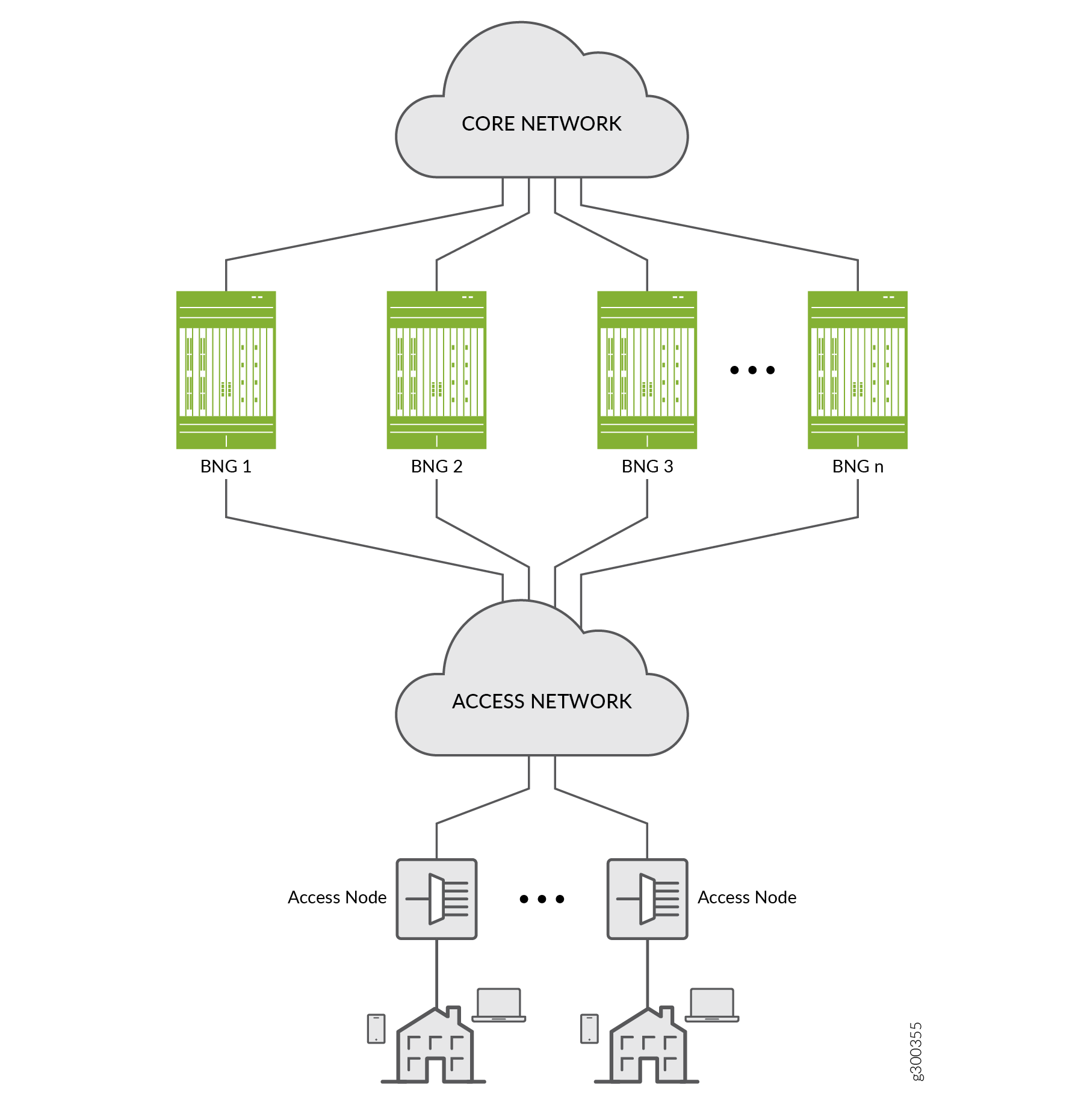
A failure in any of the locations listed in Table 1 can trigger a primary BNG to fail over to a backup BNG.
Access line card |
Core-facing link |
Access link |
Partial access network |
Chassis |
Partial core network |
You can use M:N redundancy to protect the following subscriber types:
Dynamic DHCPv4 and DHCPv6 subscribers on static 1:1 VLANs over IPoE; VRRP redundancy
VLAN-based static subscribers; VRRP redundancy
IP demux-based static subscribers; VRRP redundancy
DHCPv4 and DHCPv6 subscribers on dynamic or static VLANs over IP/MPLS; pseudowire redundancy (This support is added in Junos OS Release 20.1R1.)
- Benefits of M:N Subscriber Redundancy on BNG
- Fundamentals of M:N Redundancy
- Subscriber Sessions and Hot Standby Mode
- M:N Redundancy Using Virtual Router Redundancy Protocol (VRRP)
- VRRP Failover and Reversion Timing
- M:N Redundancy Using Pseudowire Redundancy
- DHCP Active Leasequery Topology Discovery and M:N Subscriber Redundancy
- Example Topology Discovery with VRRP Redundancy
- Example Topology Discovery with Pseudowire Redundancy
- Static Subscribers and M:N Redundancy
- Convergence and M:N Subscriber Redundancy
Benefits of M:N Subscriber Redundancy on BNG
Provides a lightweight, application-layer subscriber redundancy. You can use it to back up multiple different subscriber groups on multiple different BNG chassis. Each subscriber group has one backups in hot-standby mode.
Multiple BNGs act as both the active BNG for one or more subscriber redundancy groups and as the backup BNG for other subscriber redundancy groups at the same time.
M:N redundancy is complementary to MX Series Virtual Chassis redundancy. M:N redundancy is appropriate for distributed environments. MX Series Virtual Chassis, requires a dedicated chassis for redundancy. It provides 1:1 redundancy and is most often used in centralized deployments.
M:N redundancy with DHCP active leasequery topology discovery protects subscribers from several different hardware and software single points of failure. These include failures in access (subscriber-facing) or core-facing links and in an access interface module or the chassis. It also protects against partial access network and partial core network failures.
You can enable or disable M:N redundancy for subscribers that are active. If you remove the redundancy configuration, subscribers that had the configuration remain intact on both the primary and backup BNGs.
You can deploy M:N redundancy with a single core-facing interface. This means that multiple subscriber redundancy groups can share a common core connectivity.
M:N redundancy subscribers can coexist with nonredundancy subscribers. This means that you do not have to have BNGs that are dedicated to subscriber redundancy.
You can configure M:N redundancy subscribers at run time, even after the subscribers are UP. This is useful for software upgrades, because you can migrate subscribers to backup BNGs and then upgrade the software.
Fundamentals of M:N Redundancy
For simplicity, most of the explanation of M:N redundancy in this documentation reflects the use of DHCP subscribers on static VLANs.
The basis of M:N redundancy is that multiple (M) subscriber groups on a given BNG chassis can be backed up on multiple (N) different chassis destinations. We refer to these groups as subscriber redundancy groups.
A subscriber group consists of all subscribers that meet the following criteria:
(Static VLANs) The subscribers belong to a particular static VLAN and use the same logical access interface, such as ge-1/0/10/1. An access device, such as a switch, DSLAM or OLT, aggregates the subscribers into the common VLAN.
(Dynamic VLANs) The subscribers belong to the same dynamic VLAN and use the same physical access interface, such as ge-1/0/0.
(Static IP demux) The subscribers all have a source IP address that matches the configured subnet.
When you configure redundancy for a subscriber group, it becomes a subscriber redundancy group. A given subscriber redundancy group uses only one BNG at a time. We call this BNG the primary. For each subscriber redundancy group, only one of the other BNGs acts as a backup in hot-standby mode. When one of the errors listed in Table 1 occurs for the primary BNG, it fails over to the appropriate backup BNG for the affected redundancy group. This backup BNG is now the new primary BNG for that group. All active subscriber sessions for that subscriber redundancy group are maintained across the failover to the backup BNG.
Figure 2 is a conceptual diagram that illustrates the M:N primary/backup relationships. It shows five BNGs in an M:N primary/backup topology where each BNG has a relationship to every other BNG. If BNG 1 is the primary, you can configure BNG 2, 3, 4, and 5 as the backup BNG for different subscriber redundancy groups. If BNG 2 is the primary, you can configure BNG 1, 3, 4, and 5 as the backup BNG, and so on.
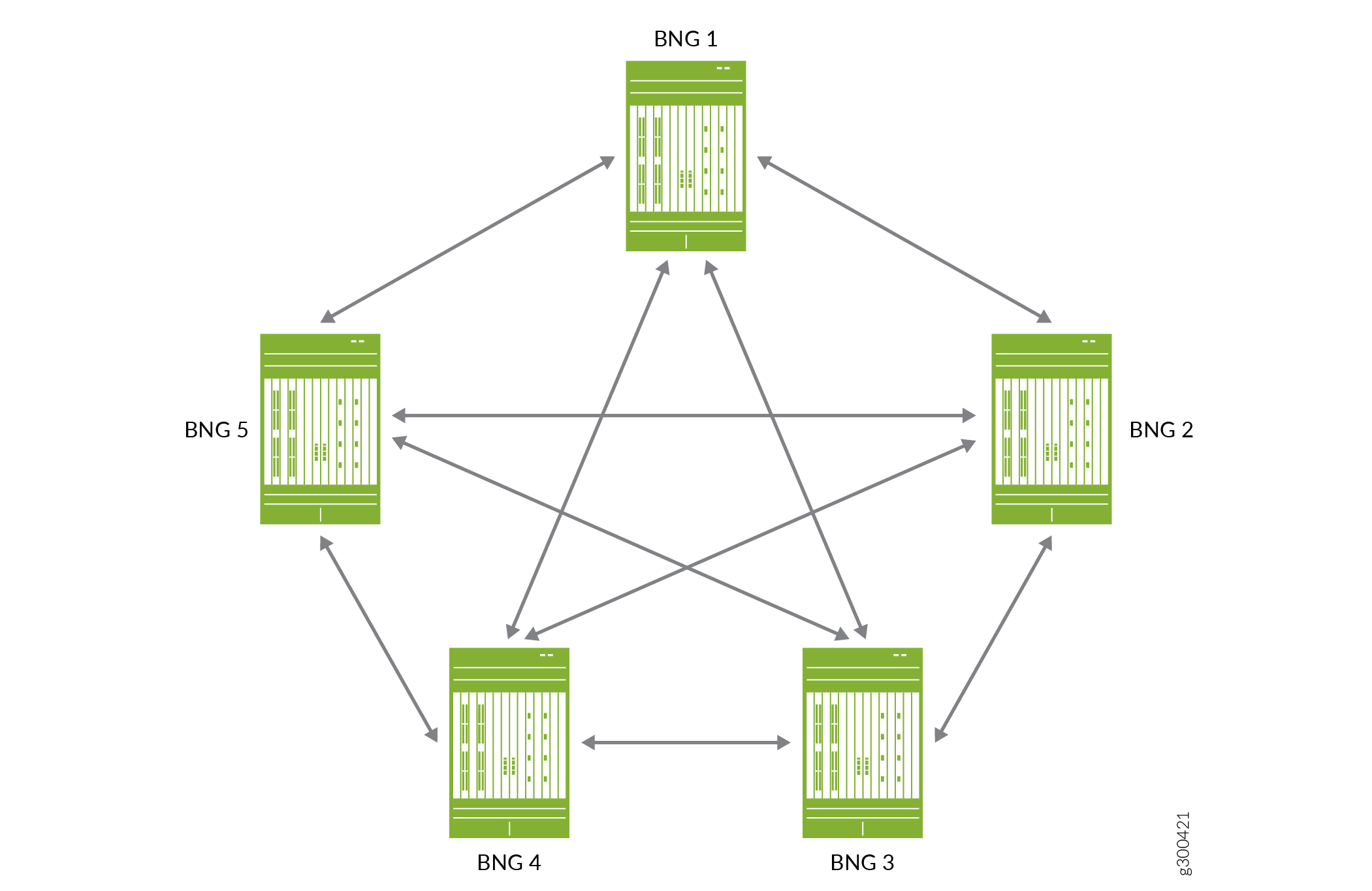
For M:N redundancy, it is important to understand that you can configure:
Only one backup BNG for each subscriber redundancy group.
A BNG to be the backup router for more than one redundancy group.
This means that a given BNG can be simultaneously both the primary router for many redundancy groups and the backup router for many different redundancy groups. When a primary BNG fails, it fails over to the backup router that you configure for each of its redundancy groups. The subscriber sessions for all redundancy groups on the primary BNG are maintained on all the backup BNGs that become new primarys for the groups.
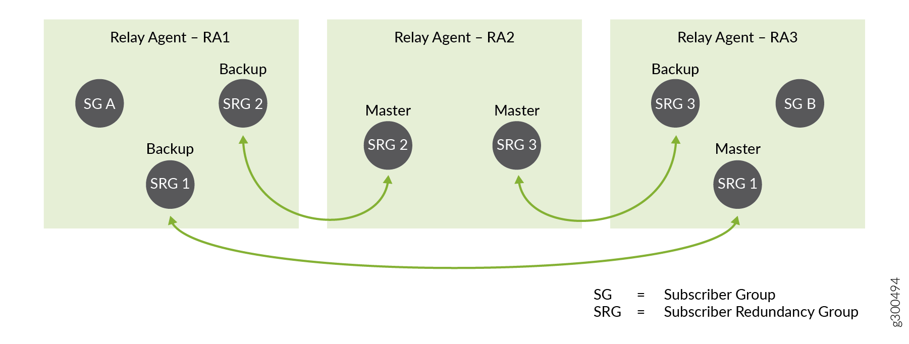
Figure 3 shows a simple configuration of subscriber groups and subscriber redundancy groups on three DHCP relay agents that are hosted on three BNGs. The BNGs might be directly connected to each other or connected over the access or core networks.
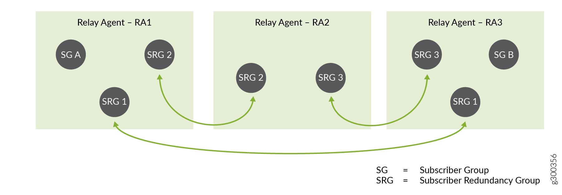
Relay agent RA1 is configured for subscriber redundancy groups, SRG 1 and SRG 2, and subscriber group SG A.
Relay agent RA2 is configured for SRG 2 and SRG 3.
Relay agent RA3 is configured for SRG 1, SRG 3, and SG B.
Another way of looking at this is that:
SRG 1 can be active or backed up on RA1 and RA3.
SRG 2 can be active or backed up on RA1 and RA2.
SRG 3 can be active or backed up on RA2 and RA3.
SG A and SG B are not backed up.
Now consider Figure 4, which shows the same topology, but indicates which BNG is primary and which is backup for each redundancy group. The BNG hosting RA 1 is the primary BNG for SRG 1 and SRG 2.
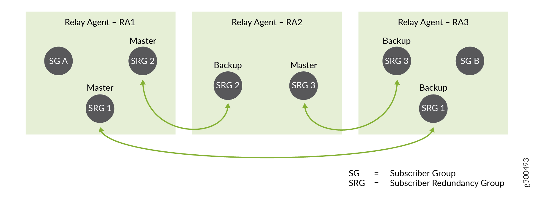
If this BNG fails, then it fails over to a different backup BNG for SRG 1 and SRG 2, as shown in Figure 5.
For SRG 1, it fails over to the BNG hosting RA 3. The RA 3 BNG becomes the new primary for SRG 1.
For SRG 2, it fails over to the BNG hosting RA 2. The RA 2 BNG becomes the new primary for SRG 2.
The failure has no effect on SRG 3.
Subscriber Sessions and Hot Standby Mode
Each backup BNG is in hot-standby mode for it’s corresponding primary BNG for each subscriber redundancy group on the backup. This means that the backup BNG is ready to take over from the primary BNG immediately and without disruption when a failover occurs. The following behaviors by the primary and backup BNG enable hot-standby mode to work.
Subscriber bindings and subscriber state are mirrored synchronously to the backup BNG, as are the primary BNG’s ARP and neighbor discovery information. Each subscriber is brought up on the backup BNG and its state is Active. Because the subscribers are active simultaneously on the primary and backup BNG, the backup BNG does not perform any subscriber processing during a failover event.
Each subscriber session is treated as a continuous session before, during, and after a failover. During initial subscriber login, the primary and backup BNGs each send a RADIUS Accounting-Start message or OCS CCR-I message for the subscriber.
During failover, the failing primary sends an Accounting-Stop or CCR-T message on a best-effort basis. For example, it sends the message if the core-facing link is still up or if the chassis is still running. If the core-facing link is down or the entire chassis is down, then the failing primary can’t send an Accounting-Stop or CCR-T message.
When the backup BNG becomes primary, it does not send an Accounting-Start or CCR-I message because the subscribers are active across the failover. Accounting statistics increment from the new primary.
During initial subscriber login, the BNG adds subscriber routes to its routing table and propagates the routes to the core network. When the primary BNG fails over, it does not delete subscriber routes from its own routing table and it does not withdraw the routes from the core network. After failover, the failed primary does not add or propagate any routes. Alternatively, you can configure the subscriber routes to be advertised to or withdrawn from the core based on BNG primary role so that there is no traffic loss as a result of the failover.
State synchronization applies only to subscriber state. Service state is not synchronized. Depending on your services configuration, the BNG might attach services for the subscribers on both active and backup subscribers. Alternatively, the services can reattach after failover on the new active BNG.
M:N subscriber redundancy does not synchronize accounting statistics from the primary BNG to the backup BNG. It does make a best-effort attempt to communicate accounting information to an accounting server. When a failover occurs, accounting statistics begin incrementing from the new primary and stop incrementing from the failed primary. Depending on the severity of the failure, failovers can result in loss of accounting information.
M:N Redundancy Using Virtual Router Redundancy Protocol (VRRP)
You can use VRRP to provide M:N redundancy in a network. M:N redundancy uses VRRP to provide a virtual IP address and MAC address shared by two BNGs in a VRRP group (sometimes referred to as a VRRP instance). The VRRP group corresponds to a single virtual router. You configure the VRRP group on the respective access interface on each BNG. The access interface is the subscriber-facing logical interface that is connected to the access network.
The virtual IP address becomes the default gateway address for the BNGs in the group. Only the BNG acting as the primary sends VRRP advertisements or responds to traffic destined for the virtual router address. The BNG advertises only the virtual gateway address and virtual MAC address to subscriber hosts. Because both routers in the group share the same virtual gateway address, no interaction with the hosts is required and failover from primary to backup occurs within a few seconds.
The VRRP solution for M:N redundancy is targeted for an N:1 subscriber access model that uses static underlying logical interfaces.
For detailed information about how VRRP works in general, see Understanding VRRP and related topic in the High Availability User Guide.
You configure different priorities for the two routers in a VRRP group to determine which router the group elects to be the primary:
The router with the higher priority for the group is the primary. The larger the number, the higher the priority. For example, between two group members with priorities of 100 and 50, respectively, the router with priority 100 is the primary.
When the primary fails, the protocol elects the backup router as the new primary. The new primary assumes ownership of the virtual IP and MAC addresses. Failover has no effect on data traffic.
-
When the original primary comes back online, the protocol determines that it has a higher priority than the current primary (previous backup). The original primary then resumes the primary role with no effect on data traffic.
Note:When using VRRP for M:N Subscriber Redundancy, the number of subscriber redundancy groups are limited to the number of supported VRRP sessions on the device. For dual-stack this feature requires separate VRRP sessions for IPv4 and IPv6, therefore the number of subscriber redundancy groups are halved.
Figure 6 shows a sample topology with two BNGs and the configuration for the corresponding interfaces on each router:
The two logical interfaces are on the same VLAN (1).
The interface addresses are in the same subnet (203.0.113.1/24 and 203.0.113.2/24).
The interface addresses are in the same VRRP group (27) and share the same virtual IP address (203.0.113.25).
The BNG with the higher priority (254) is elected primary; the BNG with the lower priority (200) is the backup.
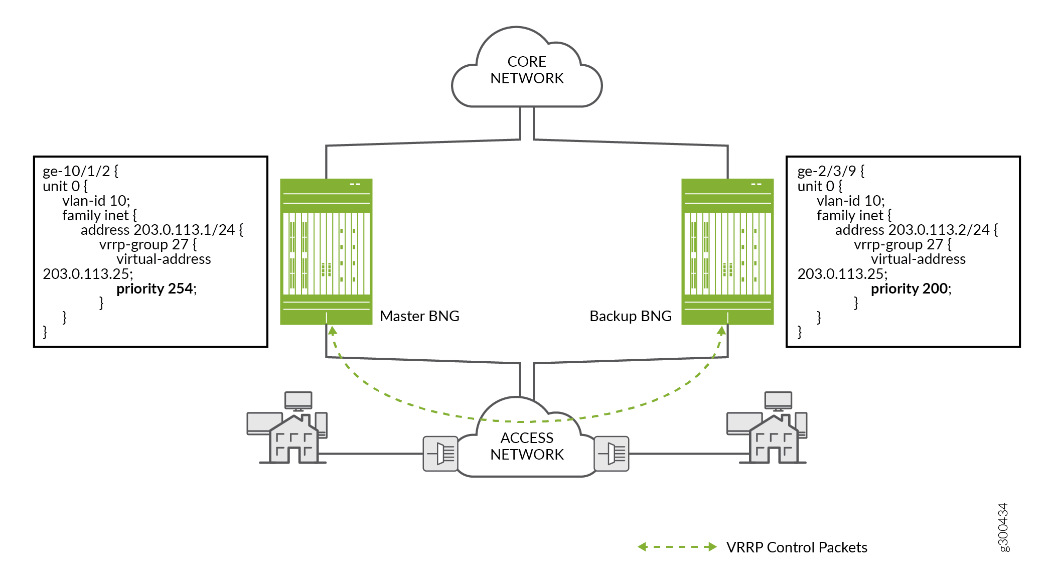
Figure 7 shows how the configured VRRP priority determines which BNG acts as the primary or backup for a subscriber redundancy group.
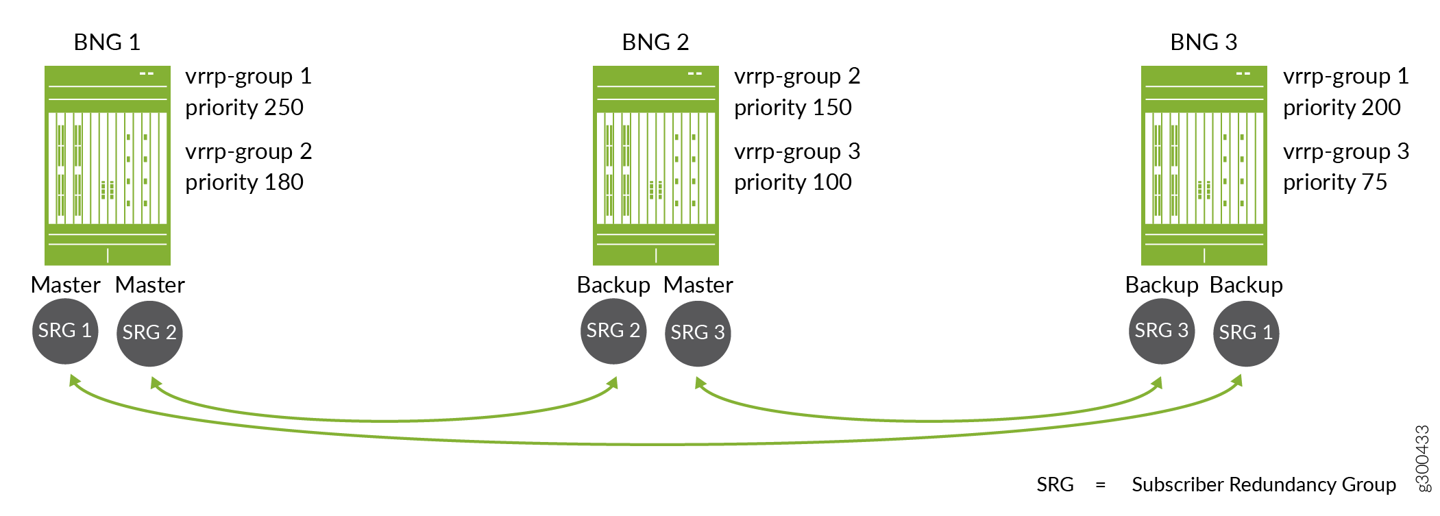
The topology includes three subscriber redundancy groups (M), SRG 1, SRG 2, and SRG 3 on three BNGs (N). Each subscriber redundancy group corresponds to a different VRRP group. The arrows indicate the primary router and backup router for each group
For SRG 1, BNG 1 has the higher priority, 250. BNG 3 has a lower priority, 200. This means that BNG 1 is the primary for SRG 1 and BNG 3 is the backup, so BNG 1 fails over to BNG 3. When BNG 1 recovers, it is reelected primary for SRG 1, because it has a higher priority than BNG 3.
For SRG 2, BNG 1 also has the higher priority, 180, and is the primary. BNG 2 has a lower priority, 150, and is the backup.
For SRG 3, BNG 2 has the higher priority, 100, and is the primary. BNG 3 has a lower priority, 75, and is the backup.
VRRP Failover and Reversion Timing
Using the redundancy configuration shown in Figure 7, suppose BNG 1 fails over to BNG 3 for SRG 1, so that BNG 3 is the new primary for the group. The primary role reverts automatically to BNG 1 when it comes back up. If the connection between the two BNGs is across the access network (as compared to a direct link between the BNGs), the subscriber states might not be synchronized between the two BNGs when the primary role reverts. VRRP state is independent of DHCP active leasequery synchronization.
When the access link on BNG 1 is restored, the DHCP active leasequery restores the connection for subscriber synchronization between the BNGs. DHCP begins to resynchronize the subscriber state and binding information from the current primary (BNG 3) to the recovered original primary (BNG 1).
Accounting statistics can be affected if the primary role reverts to BNG 1 before the resynchronization completes. For example, accounting statistics for subscribers logging in are not added to the database until resynchronization completes. Logout messages for subscribers logging out are not processed until the synch is over and the subscribers are recovered on BNG 1.
You can mitigate these effects by configuring the VRRP hold
timer (sometime called the revertive timer) so that resynchronization
completes before the original primary resumes the primary role. Use
the hold-time statement at the [edit interfaces] hierarchy level.
We recommend that you configure VRRP redundancy in non-revertive mode when you are operating at a high scale. For systems not operating at scale, you can either use non-revertive mode or configure the VRRP hold timer (sometime called the revertive timer) with values high enough that resynchronization completes before the original primary resumes the primary role.
M:N Redundancy Using Pseudowire Redundancy
Starting in Junos OS Release 20.1R1, you can use pseudowire redundancy to provide M:N redundancy when the access network consists of Layer 2 (L2) circuits over IP/MPLS. In this type of access network, LDP is the signaling protocol that distributes labels between L2 circuit neighbors. Each L2 circuit is a point-to-point pseudowire tunnel between the access node (or customer edge device) and a BNG. The network can include a heterogeneous mix of L2 or L3 devices.
Figure 8 shows a simple topology where access nodes aggregate traffic and send it across the network to a DHCP relay agent on the primary BNG. The pseudowire redundancy configuration specifies an active pseudowire (to the primary BNG) and a backup pseudowire (to the backup BNG).
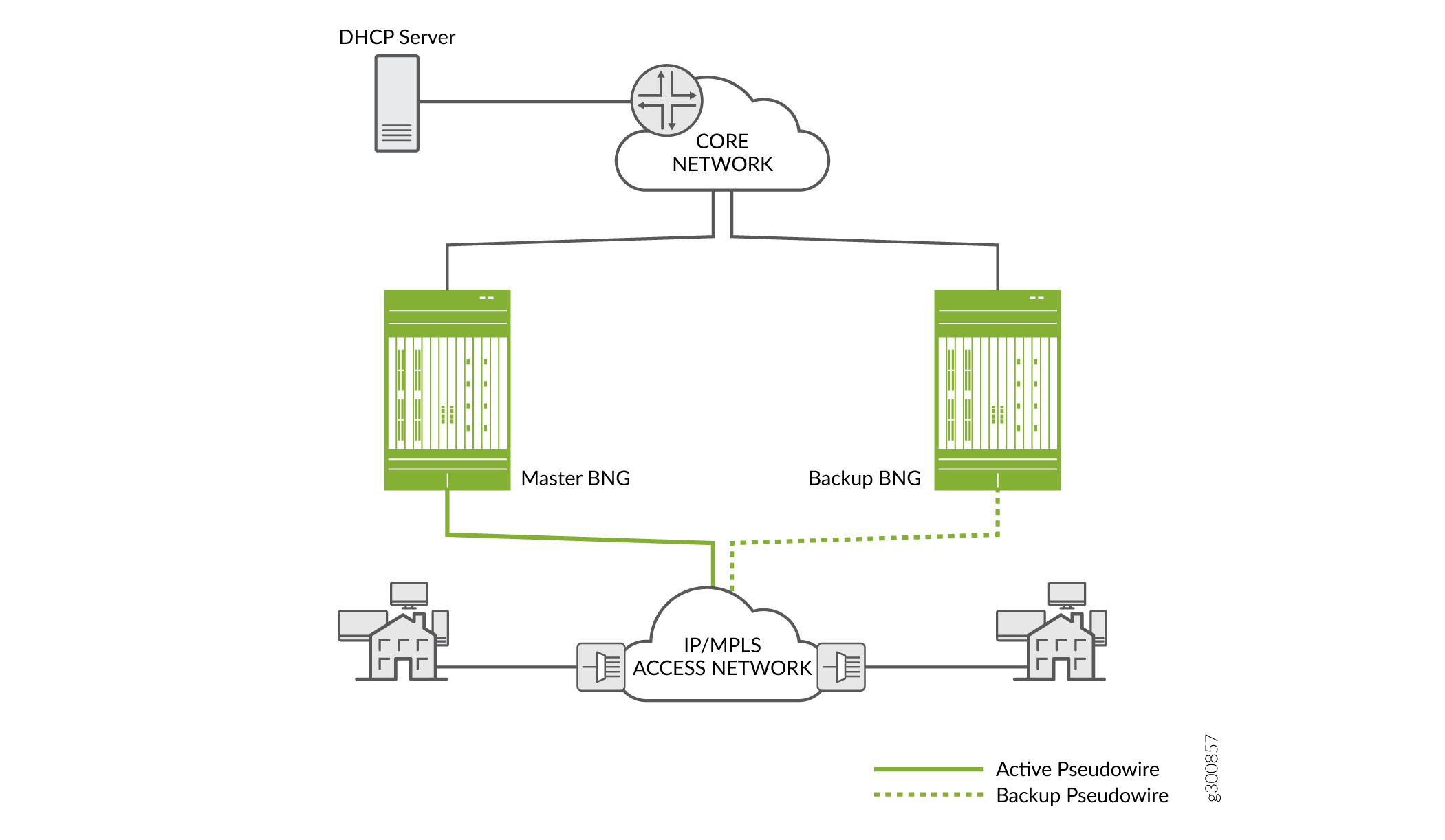
For L2 circuits, you configure the pseudowires as the underlying (access-facing) interfaces on the BNGs. You then configure the interfaces with L2 connections such as Ethernet, dynamic auto-sensed VLANs, or static VLANs. The DHCP client-facing, pseudowire interfaces are bundled and added to a L2 circuit (the pseudowire tunnel. Typically the bundle includes a set of dynamic VLAN interfaces. However, the bundle can include any combination of single VLAN logical interfaces, lists of VLAN interfaces, and physical interfaces.
An L2 circuit runs between two L2 neighbors; in this case between an access node and a BNG. Each neighbor serves as an end-point destination for an MPLS label-switched path (LSP). You construct the circuit by configuring it on an interface on each neighbor:
On the BNG, you specify the access node as a neighbor and a local pseudowire interface on the BNG that ends the L2 circuit.
On the access node, you specify the BNG as a neighbor and a local interface facing clients on the node that is the other end of the L2 circuit.
On both the BNG and access node, you configure a unique virtual circuit identifier (VCI) that distinguishes that L2 circuit from among all the other L2 circuits ending on the device.
That L2 circuit is now the primary pseudowire to the BNG. To establish redundancy, you configure the backup pseudowire on the access node. On the same local interface, you specify another BNG as the backup neighbor and specify that the backup pseudowire is in hot-standby mode.
The hot-standby mode ensures that the backup neighbor is fully ready to take over as primary if the current primary circuit fails. An LSP to the backup neighbor is already established by LDP.
The state of the pseudowire interface is UP on the primary BNG.
The state of the pseudowire interface is remote standby (RS) on the
backup BNG. (You can use the show l2circuit connections brief command to view the circuit state.) You must configure your route
policies so that subnet routes for this redundancy group are advertised
only on the primary BNG. This ensures that only the primary receives
downstream traffic.
LDP has a keepalive mechanism to detect failures. A failure results in the L2 circuit failing over from the primary pseudowire and primary BNG to the backup pseudowire and the backup BNG. When it detects a failure, LDP switches the circuit over from the primary LSP (on the primary pseudowire) to the backup LSP (on the backup pseudowire). The backup BNG assumes the primary role and its state transitions to Up.
When the old primary is up again, the same considerations regarding synchronization apply for pseudowire redundancy as they do when VRRP is the redundancy method.
We recommend that you configure pseudowire redundancy in non-revertive
mode when you are operating at a high scale. For systems not operating
at scale, you can either use non-revertive mode or configure the revert-time interval on the access node interface with values
high enough that resynchronization completes before the original primary
resumes the primary role.
DHCP Active Leasequery Topology Discovery and M:N Subscriber Redundancy
For DHCP subscribers, DHCP active leasequery and topology discovery enable subscriber state and binding information to be synchronized between peer DHCP relay agents for all subscriber redundancy groups on the peers. This enables leases and data traffic to continue without interruption both when the primary BNG fails over to the backup and when it resumes the primary role.
Although you configure interface-level primary/backup redundancy for pairs of BNGs, it also corresponds in a way to the DHCP relay agents hosted on the primary and backup BNGs. You can think of the DHCP relay agent on the primary BNG as being the primary relay agent for a subscriber redundancy group. Similarly, you can think of the DHCP relay agent on the backup BNG for a group as being the backup relay agent for the group.
Each relay agent that you configure with topology discovery exchanges messages with its configured active leasequery peers to determine the name of access interfaces on its relay agent peers that correspond to and connect with its own local access interfaces. The access interfaces are the interfaces used by the subscriber redundancy groups.
When a relay agent sends a topology discovery query message to a peer, that message includes DHCP options that specify the access interface name (Agent Circuit ID), the subnet/mask for the interface, and the VLAN ID for the redundancy group. DHCP also generates a random transaction ID for the exchange that is conveyed in the packet header. The transaction ID is unique for that access interface.
The receiving peer relay agent uses the subnet/mask and the VLAN ID to determine whether it has a local access interface for those values. If it does, the peer sends a topology discovery reply over that interface to the querying relay agent’s access interface. The reply message includes the subnet/mask, VLAN ID, and the transaction ID that it received in the query.
The querying relay agent verifies that the transaction ID in the reply matches the access interface where it received the reply. The transaction ID in the reply must correspond to the one that it sent to the peer for that access interface. If the transaction ID matches, the relay agent can then add an entry to its translation table to associate the two linked interfaces.
The querying agent repeats this process for each of its local access interfaces.
Figure 9 shows this query and response for two BNGs when you use VRRP redundancy. BNG 1 sends the query for its access interface, ge-10/1/2, to BNG 2 over the TCP connection. BNG 2 responds over the UDP connection from its associated interface, ge-2/3/9.
BNG 2 sends a query for its access interface to BNG 1 over the TCP connection. BNG 1 responds over the UDP connection from its associated interface ge-10/1/2.
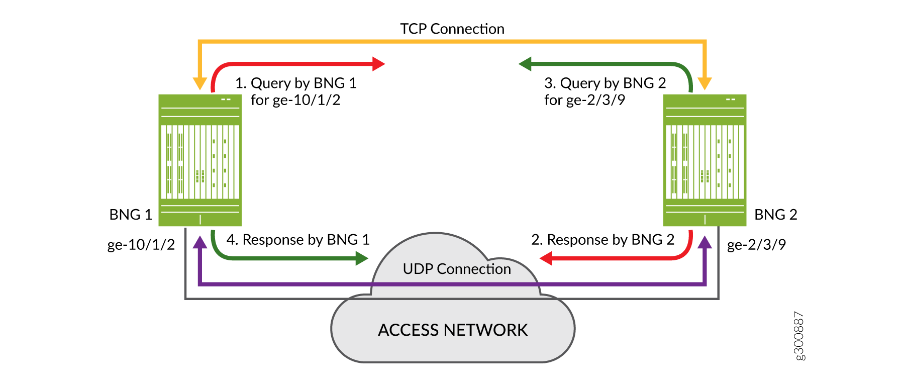
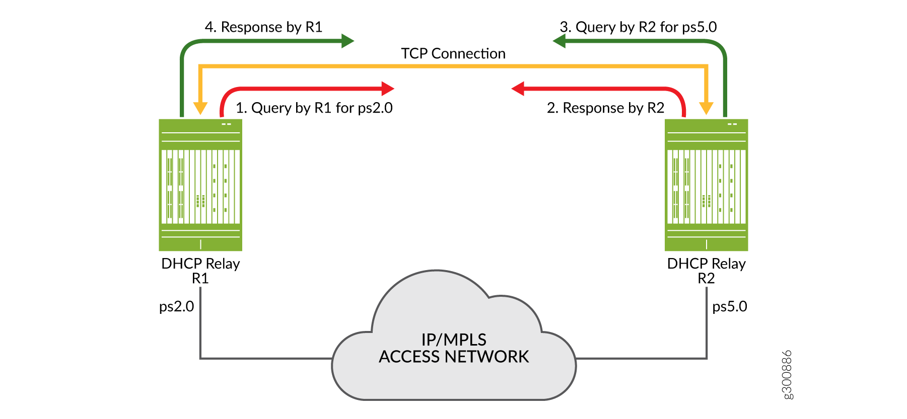
Figure 10 shows a query and response for two DHCP relay agents on BNGs when you use pseudowire redundancy. R1 sends the query for its access interface, ps2.0, to BNG 2 over the TCP connection. R2 responds over the same TCP connection. R2 also sends a query to R1, for its access interface, ps5.0. R1 then responds to this query over the TCP connection. Topology discovery for pseudowire redundancy uses a statically configured, shared common key across BNG pairs as the matching criteria. This is in contrast to VRRP redundancy where matching is performed on subnet/mask and VLAN ID.
Each peer agent sends queries to its peers so it can build its own translation table of corresponding local and remote access interfaces. In this way all relay agents that you configure both as peers and for topology discovery learn the complete set of remote access interfaces for their local interfaces. The translation tables enable the peers to synchronize subscriber information appropriately for each subscriber redundancy group.
After topology discovery is completed, active leasequery performs the subscriber synchronization. Active leasequery performs its queries by giaddr (DHCPv4) or linkaddr (DHCPv6). This query type ensures that DHCP synchronizes only the information for subscribers in a redundancy group for each interface.
You cannot configure this query type; it is a function of configuring topology discovery. When you configure topology discovery, the presence of query-by-relay-id and giaddr in DHCPv4 option 82 or linkaddr in DHCPv6 Option 18 is interpreted to be a query by giaddr or a query by linkaddr, respectively.
The relay agent uses the access interface as the value for its gateway IP address (giaddr or linkaddr) field when it sends packets to the local server on behalf of a client. The local server returns the giaddr/linkaddr when it responds to the relay agent. The relay agent then uses this value to determine where to send the information downstream. The giaddr/linkaddr shows that the packet has been sent for a particular access logical interface, so the relay agent forwards the information to the DHCP client on that interface.
What this means for subscriber redundancy is that by using the giaddr or linkaddr query, active leasequery requests only information for subscribers on that access interface. Consequently, it synchronizes only that subscriber information from the primary relay agent to the backup relay agent. This is a much smaller set of subscribers than if the active leasequery used the query-by relay-id method, which would return information for all subscribers on the entire chassis.
The result of this process is that each peer agent installs the subscribers for each redundancy group it handles. When the primary BNG/relay agent fails over, the backup already has the necessary subscriber information to maintain the session without interruption.
Example Topology Discovery with VRRP Redundancy
Figure 11 shows a simple topology where active leasequery with topology discovery is configured for the DHCP relay agent peers on two BNGs that are connected over the access network. The configured peer addresses are 192.0.2.1 and 192.0.2.2. We’ll use this illustration to understand how topology discovery works when you configure VRRP as the redundancy protocol and how the translation tables are built for each peer relay agent.
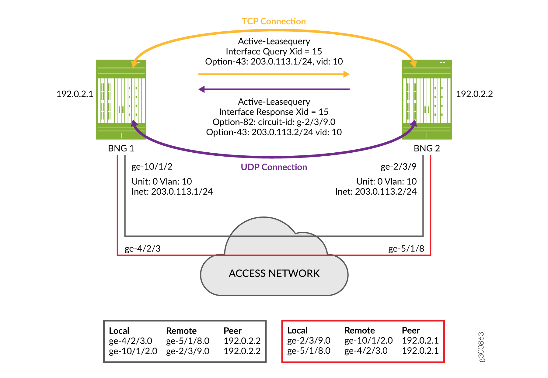
After TCP synchronization, peer 192.0.2.1 sends a topology discovery query to peer 192.0.2.2 to determine the matching remote interface for its own local interface, ge-10/1/2.0. Because this is a DHCPv4 topology, the message it sends is a DHCPLEASEQUERY. The query is sent over the TCP connection and includes the following information:
The IP subnet address and mask (203.0.113.1/24) of the local access interface, conveyed in DHCPv4 Option 43, suboption 2.
The VLAN ID (10) that is configured on the access interface, conveyed in DHCPv4 Option 43, suboption 4.
A temporary transaction ID or xid (15), conveyed in the packet header. DHCP generates a random xid for each access interface. The xid is unique across the chassis.
Also included in the query, but not shown in the figure:
The client identifier, conveyed in DHCPv4 Option 61.
Peer 192.0.2.2 receives the query and matches the received subnet address, mask, and VLAN ID to one of its local access interfaces. In this case, the match is to interface ge-2/3/9.0.
Peer 192.0.2.2 sends a response back to peer 192.0.2.1 over the UDP connection from its matching access interface, ge-2/3/9.0. The response is a DHCPLEASEACTIVE message and includes the following information:
The IP subnet address and mask (203.0.113.2/24) of the local access interface, conveyed in DHCPv4 Option 43, suboption 2.
The VLAN ID (10) that is configured on the access interface, conveyed in DHCPv4 Option 43, suboption 4.
The name of the matching interface (ge-2/3/9.0), conveyed in Option 82.
The same temporary transaction ID that it received in the query, conveyed in the IP header.
The following information is also included in the response, but it is not shown in the figure:
The client identifier, with the same value as that received in the query, in DHCPv4 Option 61.
The server identifier, in DHCPv4 Option 54.
The IP destination address in the IP header. This is the subnet address received from peer 192.0.2.1 (203.0.113.1/24).
The IP source address in the IP header. This is the subnet address (203.0.113.2/24) for this relay agent for the matching interface (ge-2/3/9.0).
Peer 192.0.2.1 receives the response over its access interface. It confirms that the transaction ID of the response matches the one it sent in the query. The transaction ID and the vendor-specific suboptions received in the response provide the relay agent with the information it needs to map the two access interfaces in its translation table.
Peer 192.0.2.2 performs the same four steps so that it can update its own translation table. Each of the associated peers initiates topology discovery for all of its local access interfaces. In this way, each peer builds a complete translation table for all of its interfaces.
Figure 11 shows the translation table for each peer that results from the exchange of messages between each pair of peers:
The relay agent on BNG 1 initiates topology discovery for its three access interfaces.
The relay agent on BNG 2 initiates topology discovery for its three access interfaces.
The relay agent on BNG 3 initiates topology discovery for its two access interfaces.
Because the transaction ID is generated for only one access interface, topology discovery is successful even when multiple interfaces share the same subnet and VLAN ID.
For example, suppose two interfaces on peer 192.0.2.2 (ge-2/3/9 and ge-11/0/7) match the subnet and VLAN ID that it received in the query.
This relay agent sends a separate response from each of these interfaces to peer 192.0.2.1’s interfaces ge-10/1/2.0 and ge-4/2/3.0. The transaction ID does not match interface ge-4/2/3.0 because the querying peer (192.0.2.1) generated the ID for interface ge-10/1/2.0. Consequently, the querying peer updates its translation table only for interface ge-10/1/2.0.
For detailed information about DHCP active leasequery, topology discovery, and how it works with M:N subscriber redundancy, see DHCP Active Leasequery and Configuring and Using DHCP Active Leasequery. The Topology Discovery Messages section in DHCP Active Leasequery provides descriptions of the information and options carried in the DHCP query and response messages.
Example Topology Discovery with Pseudowire Redundancy
Figure 12 shows a simple topology where active leasequery with topology discovery is configured for the DHCP relay agent peers on two BNGs that are connected over an IP/MPLS access network. The configured peer addresses are 198.51.100.1 and 198.51.100.5. We’ll use this illustration to understand how topology discovery works when the access network uses pseudowire tunnels over the IP/MPLS network. Topology discovery for pseudowire redundancy uses a statically configured, shared common key across BNG pairs as the matching criteria. This is in contrast to VRRP redundancy where matching is performed on subnet/mask and VLAN ID. This example also describes how the translation tables are built for each peer relay agent.
The topology shows only a TCP connection, because pseudowire M:N redundancy does not use UDP for topology discovery. In contrast, VRRP M:N redundancy uses both TCP and UDP connections.
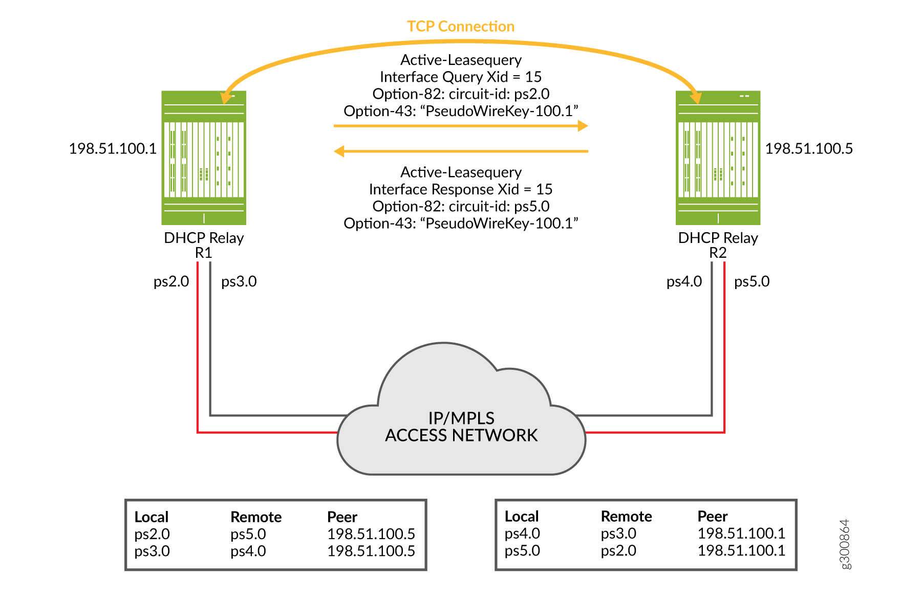
After TCP synchronization, peer 198.51.100.1 sends a topology discovery query to peer 198.51.100.5 to determine the matching remote interface for its own local interface, ps2.0. Because this is a DHCPv4 topology, the message it sends is a DHCPLEASEQUERY. The query is sent over the TCP connection and includes the following information:
The shared common key (PseudoWireKey-100.1) configured on the local interface, conveyed in DHCPv4 Option 43, suboption 6.
A temporary transaction ID or xid (15), conveyed in the packet header. DHCP generates a random xid for each access interface. The xid is unique across the chassis.
Also included in the query, but not shown in the figure:
The client identifier, conveyed in DHCPv4 Option 61.
Peer 198.51.100.5 receives the query and matches the received shared common key to one of its local access interfaces. In this case, the match is to interface ps5.0.
Peer 198.51.100.5 sends a response over the TCP connection back to peer 198.51.100.1. The response is a DHCPLEASEACTIVE message and includes the following information:
The shared common key (PseudoWireKey-100.1) that it received in the query, conveyed in DHCPv4 Option 43, suboption 6.
The same temporary transaction ID that it received in the query, conveyed in the IP header.
The name of the matching interface (ps5.0), conveyed in Option 82.
The following information is also included in the response, but it is not shown in the figure:
The client identifier, with the same value as that received in the query, in DHCPv4 Option 61.
The server identifier, in DHCPv4 Option 54.
Peer 198.51.100.1 receives the response over the in-band TCP connection. It confirms that the transaction ID of the response matches the one it sent in the query. The transaction ID and the vendor-specific suboptions received in the response provide the relay agent with the information it needs to map the two access interfaces (local interface ps2.0 and remote interface ps5.0) in its translation table.
Each of the associated peers in a topology initiates topology discovery for each of its local access interfaces. Each peer uses the same four steps described above to build a complete translation table that maps its local interfaces with peer interfaces. In this example topology, that means:
The DHCP relay agent (R1) on BNG 1 initiates topology discovery for its two access interfaces, ps2.0 and ps3.0.
The DHCP relay agent (R2) on BNG 2 initiates topology discovery for its two access interfaces, ps4.0 and ps5.0.
You can see the translation table for each peer that results from the exchange of messages between the pair of peers in Figure 12. The same shared common key is configured on both pseudowire interfaces for each pair. For example, ps2.0 and ps5.0 have the key PseudoWireKey-100.1. Interfaces ps3.0 and ps4.0 share a different key (not shown in the figure).
Now consider the slightly more complex topology ,with three peers, shown in Figure 13. Three DHCP relay agents on three BNGs all perform topology discovery for their pseudowire interfaces. The resulting translation tables are shown below each relay agent.
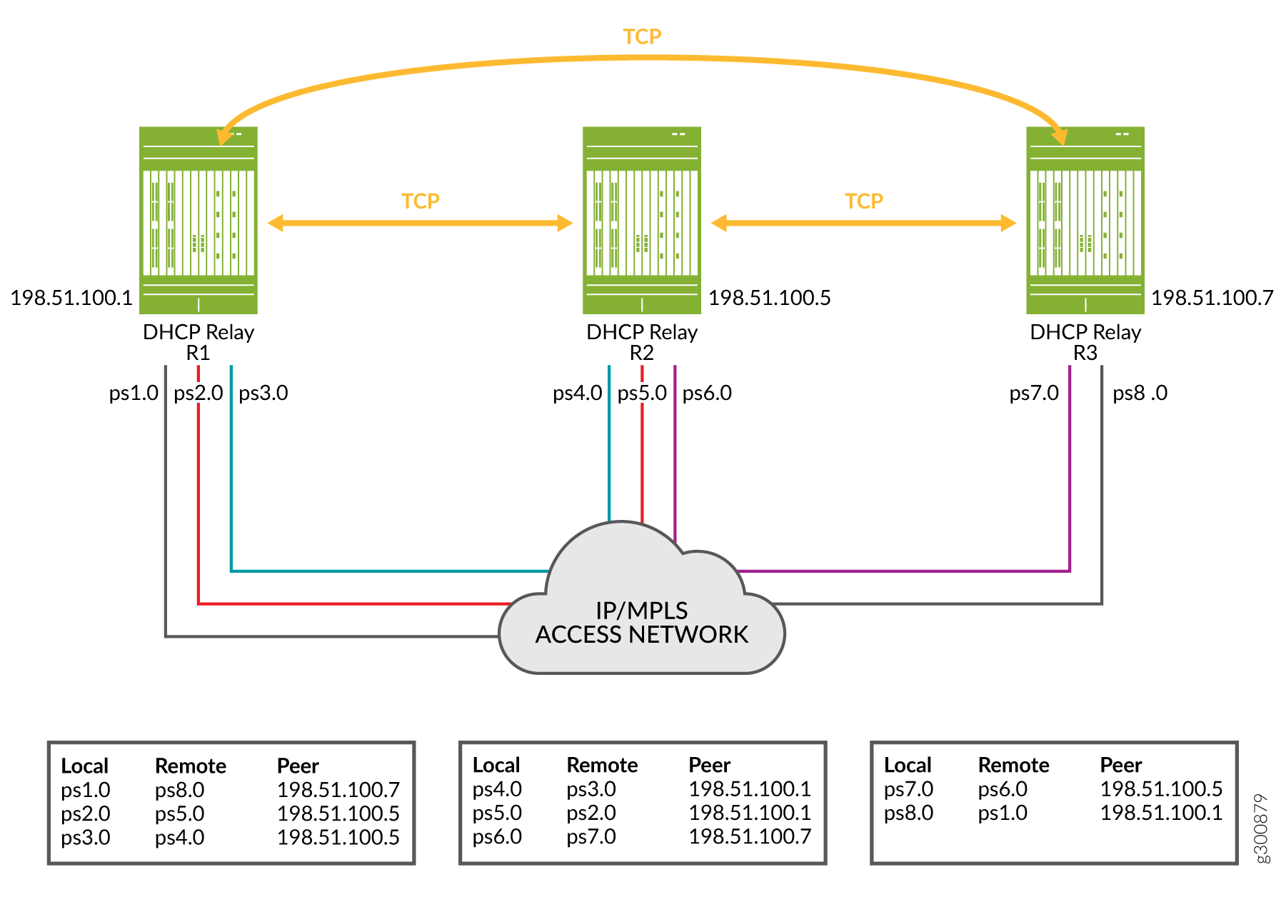
Compare the translation tables and colored pseudowire connection lines in Figure 13 with the shared key configuration snippets for each relay agent in Figure 14.
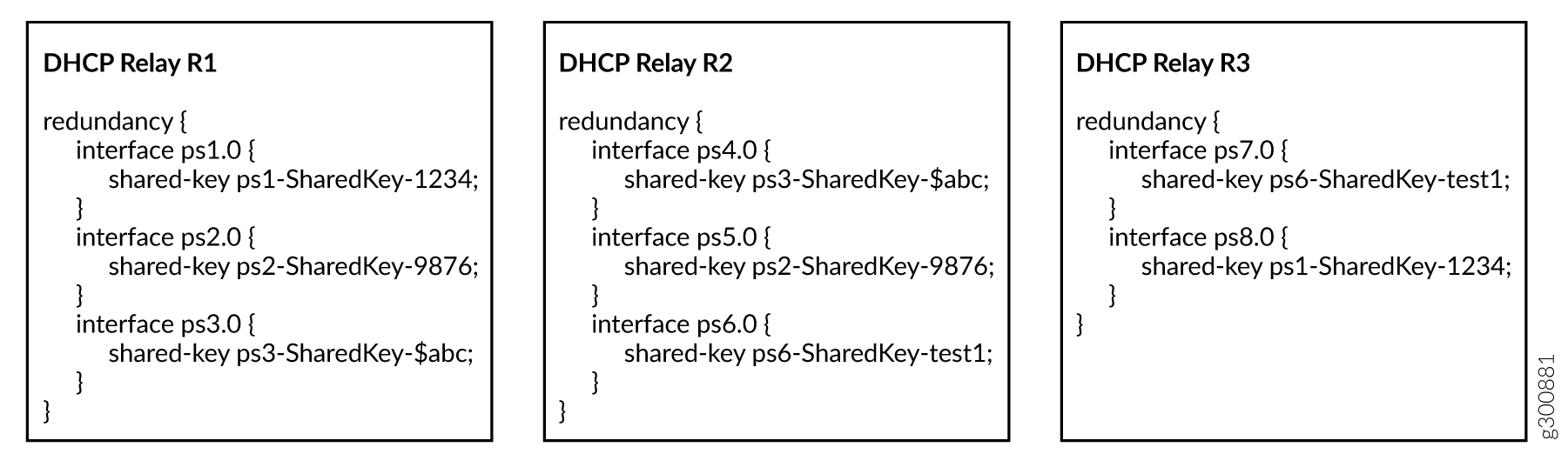
You can see that interface ps1.0 on R1 has the same shared key as interface ps8.0 on R3. The translation tables for R1 and R3 show this relationship was discovered by the topology discovery process.
Similarly, interface ps2.0 on R1 and ps5.0 on R2 have the same shared key. Again, topology discovery determined this relation ship and each agent updated its translation table accordingly. The other rows in the translation tables were populated in the same way.
For detailed information about DHCP active leasequery, topology discovery, and how it works with M:N subscriber redundancy, see DHCP Active Leasequery and Configuring and Using DHCP Active Leasequery. The Topology Discovery Messages section in DHCP Active Leasequery provides descriptions of the information and options carried in the DHCPv4 and DHCPv6 query and response messages.
Static Subscribers and M:N Redundancy
M:N subscriber redundancy supports two categories of subscribers:
Subscribers that use the DHCP client protocol over a static VLAN. This is the most common subscriber type for M:N subscriber redundancy.
Subscribers on static interfaces that are not running a client protocol. This subscriber type is typical for small to medium enterprises that have their own static IP address and do not use anything like DHCP.
Static subscribers consist of the following types:
VLAN-based static subscribers—You create subscribers on top of the VLAN logical interface. You configure the VRRP attributes on the VLAN logical interface.
IP demux-based static subscribers—You create subscribers on an IP demux interface over an underlying interface. Traffic for these subscribers includes a source IP address that matches the configured subnet for the subscriber interface. You configure VRRP attributes on the underlying logical interface.
Both of these static subscriber types are managed by the jsscd daemon. They are sometimes referred to as JSSCD static subscribers.
The following sample configuration snippets show you how to create a static subscriber group with two interfaces configured for VRRP on a primary BNG and a backup BNG. One interface is an IP demux interface and the other is a VLAN interface. The configuration shows how VRRP is configured on each interface.
Primary BNG configuration:
The following snippet configures the underlying interface for the IP demux logical interface, ge-1/1/9.11. It specifies the VLAN ID as 11. The access interface subnet is set to 203.0.113.1/24. The VRRP configuration on this subnet sets the group (the subscriber redundancy group) to 11 and specifies the address for the virtual router. The virtual router consists of the primary and backup BNGs for this subscriber redundancy group. The VRRP priority is 230. When the primary fails over to the backup, assumption of the primary role by the backup is delayed by 30 seconds.
[edit]
interfaces {
    ge-1/1/9 {
        unit 11 {
            demux-source inet;
            vlan-id 11;
            family inet {
                address 203.0.113.1/24 {
                    vrrp-group 11 {
                        virtual-address 203.0.113.25;
                        priority 230;
                        preempt {
                            hold-time 30;
                        }
                    }
                }
            }
        }
    }
}
The following snippet configures the VLAN logical interface, ge-1/1/9.20. It specifies the VLAN ID as 20. The access interface subnet is set to 192.0.2.1/24. The VRRP configuration on this subnet sets the group (the subscriber redundancy group) to 20 and specifies the address for the virtual router. The virtual router consists of the primary and backup BNGs for this subscriber redundancy group. The VRRP priority is 230. When the primary fails over to the backup, assumption of the primary role by the backup is delayed by 30 seconds.
[edit]
interfaces {
    ge-1/1/9 {
        unit 20 {
            vlan-id 20 ;
            family inet {
                address 192.0.2.1/24 {
                    vrrp-group 20 {
                        virtual-address 192.0.2.25;
                        priority 230;
                        preempt {
                            hold-time 30;
                        }
                    }
                }
            }
        }
    }
}
The following snippet configures the IP demux logical interface, demux0.1, over the underlying interface, ge-1/1/9.11. It also configures the loopback interface and enables the local address for the IP demux interface to be derived from the loopback interface.
[edit]
interfaces {
    demux0 {
        unit 1 {
            demux-options {
                underlying-interface ge-1/1/9.11;
            }
            family inet {
                unnumbered-address lo0.0;
            }
        }
    }
    lo0 {
        unit 0 {
            family inet {
                address 192.168.10.32/32;
            }
        }
    }
}
The following snippet configures a static subscriber group, static-ifl, that includes both the IP demux static subscriber interface (demux0.1) and the VLAN static subscriber interface (ge-1/1/9.20). It associates an access profile with the group, sets the password and a prefix for the username.
[edit system services]
static-subscribers {
    group static-ifl {
        access-profile {
            staticauth;
        }
        authentication {
            password "$ABC123$ABC123"; ## SECRET-DATA
            username-include {
                user-prefix test-static;
            }
        }
        interface ge-1/1/9.20;
        interface demux0.1;
    }
}
The following snippet configures an access profile for the static subscribers group.
[edit access]
profile staticauth {
    authentication-order none;
}
Backup BNG configuration:
In this example, some configuration details are different and others must be the same.
The access interfaces are different. Alternatively, you can configure the access interfaces to be the same on the primary and backup.
The VRRP priority is set to 200 for both interfaces. That value makes this the backup BNG, because it is lower than the priority on the other BNG (230).
The interface addresses are different. The virtual address is the same for both, as it must be, so that both BNGs are in the same virtual router.
The access interfaces are on the same subnet.
The following snippet configures the underlying interface for the IP demux logical interface, ge-3/0/1.11. It specifies the VLAN ID as 11. The access interface subnet is set to 203.0.113.2/24. The VRRP configuration on this subnet sets the group (the subscriber redundancy group) to 11 and specifies the address for the virtual router. The virtual router consists of the primary and backup BNGs for this subscriber redundancy group. The VRRP priority is 200. When the primary fails over to the backup, assumption of primary role by the backup is delayed by 30 seconds.
[edit]
interfaces {
    ge-3/0/1 {
        unit 11 {
            demux-source inet;
            vlan-id 11;
            family inet {
                address 203.0.113.2/24 {
                    vrrp-group 11 {
                        virtual-address 203.0.113.25;
                        priority 200;
                        preempt {
                            hold-time 30;
                        }
                    }
                }
            }
        }
    }
}
The following snippet configures the VLAN logical interface, ge-3/0/1.20. It specifies the VLAN ID as 20. The access interface subnet is set to 192.0.2.2/24. The VRRP configuration on this subnet sets the group (the subscriber redundancy group) to 20 and specifies the address for the virtual router. The virtual router consists of the primary and backup BNGs for this subscriber redundancy group. The VRRP priority is 200. When the primary fails over to the backup, assumption of the primary role by the backup is delayed by 30 seconds.
[edit]
interfaces {
    ge-3/0/1 {
        unit 20 {
            vlan-id 20 ;
            family inet {
                address 192.0.2.2/24 {
                    vrrp-group 20 {
                        virtual-address 192.0.2.25;
                        priority 200;
                        preempt {
                            hold-time 30;
                        }
                    }
                }
            }
        }
    }
}
The following snippet configures the IP demux logical interface, demux0.1, over the underlying interface, ge-3/0/1.11. It also configures the loopback interface and enables the local address for the IP demux interface to be derived from the loopback interface.
[edit]
interfaces {
    demux0 {
        unit 1 {
            demux-options {
                underlying-interface ge-3/0/1.11;
            }
            family inet {
                unnumbered-address lo0.0;
            }
        }
    }
    lo0 {
        unit 0 {
            family inet {
                address 192.168.10.32/32;
            }
        }
    }
}
The following snippet configures a static subscriber group, static-ifl, that includes both the IP demux static subscriber interface (demux0.1) and the VLAN static subscriber interface (ge-3/0/1.20). It associates an access profile with the group, sets the password and a prefix for the username.
[edit system services]
static-subscribers {
    group static-ifl {
        access-profile {
            staticauth;
        }
        authentication {
            password "$ABC123"; ## SECRET-DATA
            username-include {
                user-prefix test-static;
            }
        }
        interface ge-3/0/1.20;
        interface demux0.1;
    }
}
The following snippet configures an access profile for the static subscribers group.
[edit access]
profile staticauth {
    authentication-order none;
}
Convergence and M:N Subscriber Redundancy
Convergence is the process where routers in a network update their individual routing tables when routes on any router are added, removed, or no longer reachable because of a link failure. The routing protocols on the routers advertise the route changes throughout the network. As each router receives the updates, it recalculates the routes and then builds new routing tables based on the results.
A network is converged when all the routing tables agree on the overall network topology. For example, this means that the routers have a common understanding about which links are up or down, and so on. How long it takes the routers to reach a state of convergence is called the convergence time. The length of the convergence time depends on various factors, such as the size and complexity of the network and the performance of the routing protocols.
M:N subscriber redundancy supports both access-side (upstream) and core-side (downstream) route convergence. Because each subscriber is active simultaneously on the primary and the backup BNGs, traffic convergence can be very quick. However, route convergence is best effort and depends on the degree of failover; that is, whether a partial or complete chassis failure occurs.
It is up to you determine how to manage upstream and downstream traffic convergence for your network after a failover from primary to backup BNG.
- Upstream Traffic Convergence (VRRP Redundancy)
- Upstream Traffic Convergence (Pseudowire Redundancy)
- Downstream Traffic Convergence
Upstream Traffic Convergence (VRRP Redundancy)
You can improve upstream traffic convergence by using gratuitous ARP to reduce the time it takes for the access network to begin sending traffic to the new primary BNG after the original primary BNG fails.
On the primary BNG, the access interface or interface module goes down.
VRRP elects the backup BNG as the new primary.
The new primary broadcasts gratuitous ARP messages to the access network. It sends the messages from its access interface corresponding to the former primary’s access interface. The ARP message contains the VRRP virtual IP address and virtual MAC address that define the virtual router that includes the two BNGs.
The switch or other device on the access network relearns the gateway IP address (the virtual address). When it sends traffic to that address, the new primary BNG receives it on the access interface.
Upstream Traffic Convergence (Pseudowire Redundancy)
When you configure the primary and backup pseudowires in hot-standby mode on the access node, LDP automatically establishes LSPs to the primary and backup BNGs. The LDP signaling protocol includes a keepalive mechanism to detect failures in the path. In this case, upstream convergence is achieved by a pseudowire Layer 2 tunnel switch from the primary BNG to the backup BNG.
You can configure LDP keep-alive timers for faster detection of failures. Alternatively, you can run the BFD protocol for faster failover. Any of the following methods can cause a switch from the primary pseudowire to the backup pseudowire:
Use the
request l2circuit-switchovercommand to manually trigger a switch from the primary pseudowire to the backup pseudowire.You can configure Bidirectional Forwarding Detection (BFD) for the LDP LSPs. BFD liveness detection can detect two different kinds of failures:
A link failure in the LSP path between the access node and the primary BNG. In this case the BNG is still up.
A neighbor down failure when the primary BNG goes down.
For both types, you control the speed of the detection and switchover by the configuration of the
bfd-liveness-detectionstatement at the[edit protocols ldp oam]hierarchy level.
Downstream Traffic Convergence
The time required for downstream traffic convergence is affected by several factors, including the following:
Advertising individual subscriber routes increases the number of route recalculations that the core network routers must perform.
Detecting when an access interface goes down and then sending the appropriate route change notification to the core can sometimes be difficult or take a long time.
Routing protocols at the core might not learn immediately when either a core-facing link or the entire chassis fails. Routing protocols typically rely on some type of timeout to detect the loss, so there is always a delay waiting for the timeout to expire.
We recommend the following guidelines:
Ensure that subscriber routes are aggregated for advertisement to the core whenever possible. Aggregation might be achieved by using address pools or policy-based route advertisement as described below. Reducing the number of routes to be recalculated on the core routers reduces convergence time, especially as the scale of subscribers increases.
Configure the routes to be advertised from both BNGs with different preferences. Use fast rerouting techniques at the core.
Avoid load balancing downstream traffic between the primary and backup BNGs.
Two methods you might consider are policy-based route advertisement and dedicated BNG links.
Policy-based route advertisement (VRRP and pseudowire redundancy)—This technique can reduce downstream traffic convergence time because only aggregated routes are updated in the core network, rather than numerous individual subscriber routes. For this method, you configure BGP, OSPF, or any other routing protocol to advertise aggregated routes toward the core only when a BNG becomes the primary.
For VRRP redundancy, you configure the BGP policies to track the VRRP virtual IP address. BGP aggregates the subscriber routes based on the subscriber redundancy group corresponding to a VRRP group. BGP advertises the aggregated routes to the core when the VRRP primary role is assumed by the BNG.
For pseudowire redundancy, you configure the BGP policies to track the pseudowire interface status (Up or Down). BGP aggregates routes for the subscriber redundancy group. BGP advertises the aggregated routes to the core when the state changes to Up, meaning that the backup BNG is now the primary.
In either case, if the primary BNG fails over to the backup, BGP on the failed primary withdraws the aggregated subscriber routes for the core. When the backup BNG becomes the new primary, it in turn advertises aggregated subscriber groups to the core.
BNG dedicated links (VRRP redundancy only)—You can reduce the time it takes to detect a failure on the primary BNG by connecting the BNGs with a dedicated link. You configure VRRP on the access interface to track the state of the dedicated link interface. You also configure VRRP on the dedicated link interface to track the state of the access interface.
A failure on the access interface on the primary causes the VRRP primary role to change on the dedicated link. That change in turn causes theprimary role to change immediately on the access interface on the backup BNG. This method is faster than waiting for the VRRP hello timer to expire.
How to Configure M:N Subscriber Redundancy with VRRP and DHCP Binding Synchronization
M:N subscriber redundancy with VRRP and DHCP binding synchronization requires you to configure all of the following:
Redundant subscriber groups to specify the subscribers that are part of the primary/backup operation.
VRRP on all redundant routers in the topology. VRRP is the protocol that provides the underlying redundancy capability for the subscriber groups and DHCP relay agents.
DHCP active leasequery with topology discovery for all peer DHCP relay agents in the topology. Active leasequery is responsible for synchronizing the subscriber state and binding information among the peer relay agents. Topology discovery enables the peer relay agents to determine the remote access interfaces for their subscriber redundancy groups so that they can build translation tables of local and remote interfaces to support the M:N primary/backup redundancy scheme.
This topic describes only the basic configurations necessary for M:N subscriber redundancy on the BNGs that host the peer DHCP relay agents. It does not describe every aspect of the following: global subscriber management, the VRRP configuration that you might use in your network, DHCP relay agents, or DHCP leasequery. For more information about these subjects, see the following:
Junos OS Enhanced Subscriber Management and Configuring Junos OS Enhanced Subscriber Management
M:N subscriber redundancy requires that the primary and backup BNGs support the same protocol versions for DHCP and VRRP. If the protocol support is different between the BNGs, you might see undesirable side-effects.
Dual-stack redundancy subscribers have the following requirements:
DHCP configuration—You must configure active leasequery with topology discovery for both DHCPv4 and DHCPv6.
VRRP configuration—You must configure both address families on the access interface, because dual-stack subscribers require two sessions, one each for IPv4 and IPv6. You must also configure the same VRRP primary role priority for the IPv4 and IPv6 sessions for a given redundancy group because they share the same logical interface.
- Configure Subscriber Group Redundancy
- Configure VRRP to Support M:N Redundancy
- Configure Active Leasequery with Topology Discovery
Configure Subscriber Group Redundancy
To configure subscriber group redundancy on a BNG:
Configure VRRP to Support M:N Redundancy
To configure VRRP to support M:N redundancy for a subscriber redundancy group on a BNG:
Configure Active Leasequery with Topology Discovery
Enable active leasequery with topology discovery on the pair of DHCP relay agents that support a given subscriber redundancy group. You must repeat the configuration for each pair of relay agents for different redundancy groups.
The following steps describe the configuration for DHCPv4.
For DHCPv6, use the procedure at the [edit forwarding-options
dhcp-relay dhcpv6] hierarchy level.
For dual-stack subscribers, you must configure active leasequery with topology discovery for both DHCPv4 and DHCPv6.
Because active leasequery is an extension of bulk leasequery, you must also configure bulk leasequery for active leasequery to operate. You must configure bulk leasequery before you configure active leasequery. See Configuring and Using DHCP Bulk Leasequery.
How to Configure M:N Subscriber Redundancy with Pseudowires and DHCP Binding Synchronization
M:N subscriber redundancy with pseudowires and DHCP binding synchronization requires you to configure all of the following:
Redundant subscriber groups to specify the subscribers that are part of the primary/backup operation.
DHCP active leasequery with topology discovery for all peer DHCP relay agents in the topology. Active leasequery is responsible for synchronizing the subscriber state and binding information among the peer relay agents. Topology discovery enables the peer relay agents to determine the remote access interfaces for their subscriber redundancy groups so that they can build translation tables of local and remote interfaces to support the M:N primary/backup redundancy scheme.
M:N subscriber redundancy with pseudowires functions in an IP/MPLS network where pseudowire tunnels from an access node (such as a switch) make up the L2 circuits to the primary and backup BNGs acting as DHCP relay agents. Those configurations are outside the scope of this documentation.
This topic describes only the basic configurations necessary for M:N subscriber redundancy on the BNGs that host the peer DHCP relay agents. It does not describe every aspect of the following: global subscriber management, DHCP relay agents, or DHCP leasequery. It does not describe how to configure your IP/MPLS network, the access node that creates the L2 circuits to the DHCP relay agents, or the pseudowire tunnels. For more information about these subjects, see the following:
Junos OS Enhanced Subscriber Management and Configuring Junos OS Enhanced Subscriber Management
MPLS Pseudowire Subscriber Logical Interfaces
Redundant Pseudowires for Layer 2 Circuits and VPLS
M:N subscriber redundancy requires that the primary and backup BNGs support the same protocol versions for DHCP. If the protocol support is different between the BNGs, you might see undesirable side-effects.
Dual-stack redundancy subscribers have the following requirement:
DHCP configuration—You must configure active leasequery with topology discovery for both DHCPv4 and DHCPv6.
Configure Subscriber Group Redundancy
To configure subscriber group redundancy on a BNG:
For example, you might configure the following on one BNG:
[edit system services subscriber-management redundancy]
user@host# set protocol pseudo-wire
user@host# set interface ps2.0 local-inet-address 10.80.1.2
user@host# set interface ps2.0 local-inet6-address 2001:db8::
user@host# set interface ps2.0 shared-key pskey-2.0-abc-215
user@host# set interface ps3.0 local-inet-address 10.10.0.1
user@host# set interface ps3.0 local-inet6-address 2001:db8:ff:f8::
user@host# set interface ps3.0 shared-key pskey-3.0-def-43
user@host# set no-advertise-routes-on-backup
Then configure the following on a peer BNG. Note that ps5.0 on this BNG shares the same key as ps2.0 on the other. That signifies that ps2.0 and ps5.0 are the associated access interfaces for pseudowire redundancy. Similarly, associated interfaces ps3.0 and ps4.0 have the same shared key as each other.
[edit system services subscriber-management redundancy]
user@host# set protocol pseudo-wire
user@host# set interface ps4.0 local-inet-address 10.55.3.0
user@host# set interface ps4.0 local-inet6-address 2001:db8:1C:44::
user@host# set interface ps4.0 shared-key pskey-3.0-def-43
user@host# set interface ps5.0 local-inet-address 10.60.20.1
user@host# set interface ps5.0 local-inet6-address 2001:db8:01:10:cd::
user@host# set interface ps5.0 shared-key pskey-2.0-abc-215
user@host# set no-advertise-routes-on-backup
Configure Active Leasequery with Topology Discovery
Enable active leasequery with topology discovery on the pair of DHCP relay agents that support a given subscriber redundancy group. You must repeat the configuration for each pair of relay agents for different redundancy groups.
The following steps describe the configuration for DHCPv4.
For DHCPv6, use the procedure at the [edit forwarding-options
dhcp-relay dhcpv6] hierarchy level.
For dual-stack subscribers, you must configure active leasequery with topology discovery for both DHCPv4 and DHCPv6.
Because active leasequery is an extension of bulk leasequery, you must also configure bulk leasequery for active leasequery to operate. You must configure bulk leasequery before you configure active leasequery. See Configuring and Using DHCP Bulk Leasequery.
Verifying M:N Redundancy and Active Leasequery Topology Discovery Information
Purpose
Determine status information and statistics for access interfaces, relay agents, and subscribers that are part of your topology for M:N redundancy with DHCP active leasequery topology discovery.
Action
To verify the VRRP redundancy state of access interfaces:
user@host>show vrrp
To verify that the redundancy state of a specified access logical interface is
Masteron the primary relay agent andBackupon the backup relay agent:user@host>show system subscriber-management redundancy-state dhcp active-leasequery interface interface-name
This interface can be either a subscriber interface or the underlying VLAN interface. For VRRP redundancy, the redundancy state is the same as the VRRP state of the underlying logical interface. For pseudowire redundancy, the redundancy state is based on the state of the pseudowire interface.
To verify that subscribers in a redundancy group are active on both the primary and backup relay agents:
user@host>show subscribers option
The
show subscriberscommand has a number of options; you can display subscribers by IP address, interface name, VLAN ID, Agent Circuit ID, subscriber state, and so on.To verify that the DHCP relay binding information is the same for the subscribers in a redundancy group on both the primary and backup relay agents:
user@host>show dhcp relay binding verbose
user@host>show dhcpv6 relay binding verbose
You can also specify results for an IP address or an interface.
To view a list of all active leasequery peers:
user@host>show dhcp relay active-leasequery summary
user@host>show dhcpv6 relay active-leasequery summary
To view the topology discovery translation table for a peer relay agent, including the local and remote circuit IDs (access interfaces), local access interface address, transaction ID (xid), and the state of topology discovery, redundancy, and subscriber synchronization:
user@host>show dhcp relay active-leasequery peer address details
user@host>show dhcpv6 relay active-leasequery peer address details
To view active leasequery statistics, such as the number of DHCP bindings sent or received for an interface or peer.
user@host>show dhcp relay active-leasequery statistics (interface interface-name | peer ip-address)
user@host>show dhcpv6 relay active-leasequery statistics (interface interface-name | peer ipv6-address)
To clear active leasequery statistics.
user@host>clear dhcp relay active-leasequery statistics (interface interface-name | peer ip-address)
user@host>clear dhcpv6 relay active-leasequery statistics (interface interface-name | peer ipv6-address)
Change History Table
Feature support is determined by the platform and release you are using. Use Feature Explorer to determine if a feature is supported on your platform.