Example: Configuring Filter-Based Forwarding to a Specific Outgoing Interface or Destination IP Address
Understanding Filter-Based Forwarding to a Specific Outgoing Interface or Destination IP Address
Policy-based routing (also known as filter-based forwarding) refers to the use of firewall filters that are applied to an interface to match certain IP header characteristics and to route only those matching packets differently than the packets would normally be routed.
Starting in Junos OS Release 12.2, you can use then next-interface, then next-ip, or then next-ip6 as an action
in a firewall filter. From specific
match conditions, IPv4 and IPv6 addresses or an interface name can
be specified as the response action to a match.
The set of match conditions can be as follows:
Layer-3 properties (for example, the source or destination IP address or the TOS byte)
Layer-4 properties (for example, the source or destination port)
The route for the given IPv4 or IPv6 address has to be present
in the routing table for policy-based routing to take effect. Similarly,
the route through the given interface has to be present in the forwarding
table for next-interface action to take effect. This can
be achieved by configuring an interior gateway protocol (IGP), such
as OSPF or IS-IS, to advertise Layer 3 routes.
The firewall filter matches the conditions and forwards the packet to one of the following:
An IPv4 address (using the
next-ipfirewall filter action)An IPv6 address (using the
next-ip6firewall filter action)An interface (using the
next-interfacefirewall filter action)
Suppose, for example, that you want to offer services to your
customers, and the services reside on different servers. An example
of a service might be hosted DNS or hosted FTP. As customer traffic
arrives at the Juniper Networks routing device, you can use filter-based
forwarding to send traffic to the servers by applying a match condition
on a MAC address or an IP address or simply an incoming interface
and send the packets to a certain outgoing interface that is associated
with the appropriate server. Some of your destinations might be IPv4
or IPv6 addresses, in which case the next-ip or next-ip6 action is useful.
Optionally, you can associate the outgoing interfaces or IP addresses with routing instances.
For example:
firewall {
    filter filter1 {
        term t1 {
            from {
                source-address {
                    10.1.1.3/32;
                }
            }
            then {

                next-interface {
                    xe-0/1/0.1;
                    routing-instance rins1;
                }
            }
        }
        term t2 {
            from {
                source-address {
                    10.1.1.4/32;
                }
            }
            then {
                next-interface {
                    xe-0/1/0.2;
                    routing-instance rins2;
                }
            }
        }
    }
}
routing-instances {
    rins1 {
        instance-type virtual-router;
        interface xe-0/1/0.1;
    }
    rins2 {
        instance-type virtual-router;
        interface xe-0/1/0.2;
    }
}
See Also
Example: Configuring Filter-Based Forwarding to a Specific Outgoing Interface
This example shows how to use then next-interface as an action in a firewall filter.
Requirements
This example has the following hardware and software requirements:
MX Series 5G Universal Routing Platform as the routing device with the firewall filter configured.
Junos OS Release 12.2 running on the routing device with the firewall filter configured.
The filter with the
next-interface(ornext-ip) action can only be applied to an interface that is hosted on a Trio MPC. If you apply the filter to an I-chip based DPC, the commit operation fails.The outgoing interface referred to in the
next-interface interface-nameaction can be hosted on a Trio MPC or an I-chip based DPC.
Overview
In this example, Device R1 has two loopback interface addresses configured: 172.16.1.1 and 172.16.2.2.
On Device R2, a firewall filter has multiple terms configured. Each term matches one of the source addresses in incoming traffic, and routes the traffic to specified outgoing interfaces. The outgoing interfaces are configured as VLAN-tagged interfaces between Device R2 and Device R3.
IS-IS is used for connectivity among the devices.
Figure 1 shows the topology used in this example.
This example shows the configuration on Device R2.
Topology
Configuration
Procedure
CLI Quick Configuration
To quickly configure
this example, copy the following commands, paste them into a text
file, remove any line breaks, change any details necessary to match
your network configuration, and then copy and paste the commands into
the CLI at the [edit] hierarchy level.
Device R2
set interfaces ge-2/1/0 unit 0 family inet filter input filter1
set interfaces ge-2/1/0 unit 0 family inet address 10.0.0.10/30
set interfaces ge-2/1/0 unit 0 description to-R1
set interfaces ge-2/1/0 unit 0 family iso
set interfaces ge-2/1/1 vlan-tagging
set interfaces ge-2/1/1 description to-R3
set interfaces ge-2/1/1 unit 0 vlan-id 1001
set interfaces ge-2/1/1 unit 0 family inet address 10.0.0.13/30
set interfaces ge-2/1/1 unit 0 family iso
set interfaces ge-2/1/1 unit 1 vlan-id 1002
set interfaces ge-2/1/1 unit 1 family inet address 10.0.0.25/30
set interfaces ge-2/1/1 unit 1 family iso
set interfaces lo0 unit 0 family inet address 10.255.4.4/32
set interfaces lo0 unit 0 family iso address 49.0001.0010.0000.0404.00
set firewall family inet filter filter1 term t1 from source-address 172.16.1.1/32
set firewall family inet filter filter1 term t1 then next-interface ge-2/1/1.0
set firewall family inet filter filter1 term t2 from source-address 172.16.2.2/32
set firewall family inet filter filter1 term t2 then next-interface ge-2/1/1.1
set protocols isis interface all level 1 disable
set protocols isis interface fxp0.0 disable
set protocols isis interface lo0.0
Step-by-Step Procedure
The following example requires you to navigate various levels in the configuration hierarchy. For information about navigating the CLI, see Use the CLI Editor in Configuration Mode in the Junos OS CLI User Guide.
To configure Device R2:
Configure the interfaces.
[edit interfaces]
user@R2# set ge-2/1/0 unit 0 family inet filter input filter1
user@R2# set ge-2/1/0 unit 0 family inet address 10.0.0.10/30
user@R2# set ge-2/1/0 unit 0 description to-R1
user@R2# set ge-2/1/0 unit 0 family iso
user@R2# set ge-2/1/1 vlan-tagging
user@R2# set ge-2/1/1 description to-R3
user@R2# set ge-2/1/1 unit 0 vlan-id 1001
user@R2# set ge-2/1/1 unit 0 family inet address 10.0.0.13/30
user@R2# set ge-2/1/1 unit 0 family iso
user@R2# set ge-2/1/1 unit 1 vlan-id 1002
user@R2# set ge-2/1/1 unit 1 family inet address 10.0.0.25/30
user@R2# set ge-2/1/1 unit 1 family iso
user@R2# set lo0 unit 0 family inet address 10.255.4.4/32
user@R2# set lo0 unit 0 family iso address 49.0001.0010.0000.0404.00
Configure the firewall filter.
[edit firewall family inet filter filter1]
user@R2# set term t1 from source-address 172.16.1.1/32
user@R2# set term t1 then next-interface ge-2/1/1.0
user@R2# set term t2 from source-address 172.16.2.2/32
user@R2# set term t2 then next-interface ge-2/1/1.1
Enable IS-IS on the interfaces.
[edit protocols is-is]
user@R2# set interface all level 1 disable
user@R2# set interface fxp0.0 disable
user@R2# set interface lo0.0
Results
From configuration mode, confirm your configuration
by entering the show interfaces, show firewall, and show protocols commands. If the output does not
display the intended configuration, repeat the configuration instructions
in this example to correct it.
user@R2# show interfaces
ge-2/1/0 {
    unit 0 {
        description to-R1;
        family inet {
            filter {
                input filter1;
            }
            address 10.0.0.10/30;
        }
        family iso;
    }
}
ge-2/1/1 {
    description to-R3;
    vlan-tagging;
    unit 0 {
        vlan-id 1001;
        family inet {
            address 10.0.0.13/30;
        }
        family iso;
    }
    unit 1 {
        vlan-id 1002;
        family inet {
            address 10.0.0.25/30;
        }
        family iso;
    }
}
lo0 {
    unit 0 {
        family inet {
            address 10.255.4.4/32;
        }
        family iso {
            address 49.0001.0010.0000.0404.00;
        }
    }
}
user@R2# show firewall
family inet {
    filter filter1 {
        term t1 {
            from {
                source-address {
                    172.16.1.1/32;
                }
            }
            then {
                next-interface {
                ge-2/1/1.0;
            }
        }
        term t2 {
            from {
                source-address {
                    172.16.2.2/32;
                }
            }
            then {
                next-interface {
                    ge-2/1/1.1;
                }
            }
        }
    }
}
user@R2# show protocols
isis {
    interface all {
        level 1 disable;
    }
    interface fxp0.0 {
        disable;
    }
    interface lo0.0;
}
If you are done configuring the device, enter commit from configuration mode.
Verification
Confirm that the configuration is working properly.
Checking the Paths Used
Purpose
Make sure that the expected paths are used when sending traffic from Device R1 to Device R4.
Action
On Device R1, enter the traceroute command.
user@R1> traceroute 10.255.6.6 source 172.16.1.1
traceroute to 10.255.6.6 (10.255.6.6) from 172.16.1.1, 30 hops max, 40 byte packets
 1  10.0.0.10 (10.0.0.10)  0.976 ms  0.895 ms  0.815 ms
 2  10.0.0.14 (10.0.0.14)  0.868 ms  0.888 ms  0.813 ms
 3  10.255.6.6 (10.255.6.6)  1.715 ms  1.442 ms  1.382 ms
user@R1> traceroute 10.255.6.6 source 172.16.2.2
traceroute to 10.255.6.6 (10.255.6.6) from 172.16.2.2, 30 hops max, 40 byte packets
 1  10.0.0.10 (10.0.0.10)  0.973 ms  0.907 ms  0.782 ms
 2  10.0.0.26 (10.0.0.26)  0.844 ms  0.890 ms  0.852 ms
 3  10.255.6.6 (10.255.6.6)  1.384 ms  1.516 ms  1.462 ms
Meaning
The output shows that the second hop changes, depending
on the source address used in the traceroute command.
To verify this feature, a traceroute operation is performed on Device R1 to Device R4. When the source IP address is 172.16.1.1, packets are forwarded out the ge-2/1/1.0 interface on Device R2. When the source IP address is 172.16.2.2, packets are forwarded out the ge-2/1/1.1 interface on Device R2.
Example: Configuring Filter-Based Forwarding to a Specific Destination IP Address
This example shows how to use then next-ip as an action in a firewall filter.
Requirements
This example has the following hardware and software requirements:
MX Series 5G Universal Routing Platform as the routing device with the firewall filter configured.
Junos OS Release 12.2 running on the routing device with the firewall filter configured.
The filter with the
next-interface(ornext-ip) action can only be applied to an interface that is hosted on a Trio MPC. If you apply the filter to an I-chip based DPC, the commit operation fails.The outgoing interface referred to in the next-interface interface-name action can be hosted on a Trio MPC or an I-chip based DPC.
Overview
In this example, Device R2 has two routing instances that are interconnected with physical links. Traffic from certain sources is required to be directed across the upper link for inspection by a traffic optimizer, which acts transparently on the IP layer. When the traffic optimizer fails, the traffic moves to the lower link. Flows in direction R1>R3 and R3>R1 follow identical paths.
Figure 2 shows the topology used in this example.
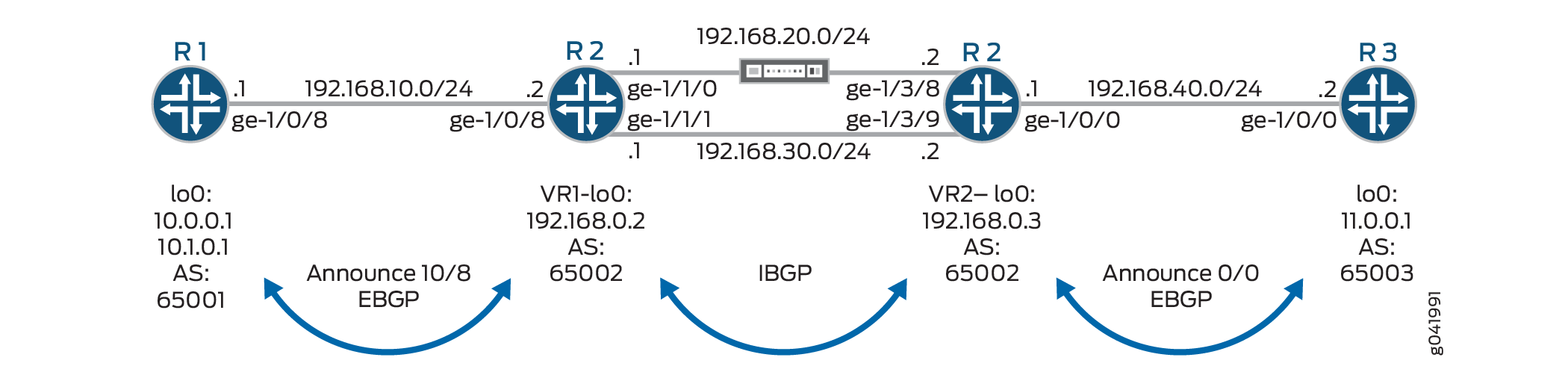
On Device R2, a firewall filter is applied to interface ge-1/0/8 in the input direction. The second term matches the specific source addresses 10.0.0.0/24, and routes the traffic to address 192.168.0.3. This address resolves to next-hop 192.168.20.2. If the link connected to interface ge-1/1/0 goes down, the address 192.168.0.3 will resolve to next-hop 192.168.30.2.
On Device R2, a firewall filter is applied to interface ge-1/0/0 in the input direction. The second term matches the specific destination addresses 10.0.0.0/24, and routes the traffic to address 192.168.0.2. This address resolves to next-hop 192.168.20.1. If the link connected to interface ge-1/3/8 goes down, the address 192.168.0.2 will resolve to next-hop 192.168.30.1.
The address configured using the next-ip action
is not automatically resolved. On Ethernet interfaces, it is assumed
that the configured address is resolved using a routing protocol or
static routes.
Internal BGP (IBGP) is used between Device R2-VR1 and Device R2-VR2. External BGP (EBGP) is used between Device R1 and Device R2-VR1, as well as between Device R2-VR2 and Device R3.
BGP operations proceed as follows:
R2-VR1 learns 10/8 from R1, and 0/0 from R2-VR2.
R2-VR2 learns 0/0 from R3, and 10/8 from R2-VR1.
R1 advertises 10/8, and receives 0/0 from R2-VR1.
R3 advertises 0/0, and receives 10/8 from R2-VR2.
The firewall filter applied to Device R2 needs to allow control-plane traffic for the directly connected interfaces, in this case the EBGP sessions.
This example shows the configuration on Device R2.
Topology
Configuration
Procedure
CLI Quick Configuration
To quickly configure this
example, copy the following commands, paste them into a text file,
remove any line breaks, change any details necessary to match your
network configuration, and then copy and paste the commands into the
CLI at the [edit] hierarchy level.
Device R1
set interfaces lo0 unit 0 family inet address 10.0.0.1/32
set interfaces lo0 unit 0 family inet address 10.1.0.1/32
set interfaces ge-1/0/8 unit 0 family inet address 192.168.10.1/24
set routing-options autonomous-system 64501
set protocols bgp group eBGP neighbor 192.168.10.2 peer-as 64502
set protocols bgp group eBGP export Announce10
set policy-options policy-statement Announce10 term 1 from route-filter 10.0.0.0/8 exact
set policy-options policy-statement Announce10 term 1 then accept
set policy-options policy-statement Announce10 term 2 then reject
Device R2
set interfaces ge-1/0/8 unit 0 family inet address 192.168.10.2/24
set interfaces ge-1/0/8 unit 0 family inet filter input SteerSrcTrafficOptimizer
set interfaces ge-1/1/0 unit 0 family inet address 192.168.20.1/24
set interfaces ge-1/1/1 unit 0 family inet address 192.168.30.1/24
set routing-instances VR1 instance-type virtual-router
set routing-instances VR1 interface ge-1/0/8.0
set routing-instances VR1 interface ge-1/1/0.0
set routing-instances VR1 interface ge-1/1/1.0
set routing-instances VR1 routing-options static route 192.168.0.3 next-hop 192.168.20.2
set routing-instances VR1 routing-options static route 192.168.0.3 qualified-next-hop 192.168.30.2 metric 100
set routing-instances VR1 routing-options autonomous-system 64502
set routing-instances VR1 protocols bgp group eBGP neighbor 192.168.10.1 peer-as 64501
set routing-instances VR1 protocols bgp group iBGP neighbor 192.168.30.2 peer-as 64502
set routing-instances VR1 protocols bgp group iBGP neighbor 192.168.30.2 export AcceptExternal
set firewall family inet filter SteerSrcTrafficOptimizer term 0 from source-address 192.168.10.0/24
set firewall family inet filter SteerSrcTrafficOptimizer term 0 then accept
set firewall family inet filter SteerSrcTrafficOptimizer term 1 from source-address 10.0.0.0/24
set firewall family inet filter SteerSrcTrafficOptimizer term 1 then next-ip 192.168.0.3 routing-instance VR1
set firewall family inet filter SteerSrcTrafficOptimizer term 2 from source-address 10.0.0.0/8
set firewall family inet filter SteerSrcTrafficOptimizer term 2 then accept
set interfaces ge-1/0/0 unit 0 family inet address 192.168.40.1/24
set interfaces ge-1/0/0 unit 0 family inet filter input SteerDstTrafficOptimizer
set interfaces ge-1/3/8 unit 0 family inet address 192.168.20.2/24
set interfaces ge-1/3/9 unit 0 family inet address 192.168.30.2/24
set routing-instances VR2 instance-type virtual-router
set routing-instances VR2 interface ge-1/0/0.0
set routing-instances VR2 interface ge-1/3/8.0
set routing-instances VR2 interface ge-1/3/9.0
set routing-instances VR2 routing-options static route 192.168.0.2/32 next-hop 192.168.20.1
set routing-instances VR2 routing-options static route 192.168.0.2/32 qualified-next-hop 192.168.30.1 metric 100
set routing-instances VR2 routing-options autonomous-system 64502
set routing-instances VR2 protocols bgp group eBGP neighbor 192.168.40.2 peer-as 64503
set routing-instances VR2 protocols bgp group iBGP neighbor 192.168.30.1 peer-as 64502
set routing-instances VR2 protocols bgp group iBGP neighbor 192.168.30.1 export AcceptExternal
set firewall family inet filter SteerDstTrafficOptimizer term 0 from source-address 192.168.40.0/24
set firewall family inet filter SteerDstTrafficOptimizer term 0 then accept
set firewall family inet filter SteerDstTrafficOptimizer term 1 from destination-address 10.0.0.0/24
set firewall family inet filter SteerDstTrafficOptimizer term 1 then next-ip 192.168.0.2 routing-instance VR2
set firewall family inet filter SteerDstTrafficOptimizer term 2 from destination-address 10.0.0.0/8
set firewall family inet filter SteerDstTrafficOptimizer term 2 then accept
set policy-options policy-statement AcceptExternal term 1 from route-type external
set policy-options policy-statement AcceptExternal term 1 then accept
Device R3
set interfaces lo0 unit 0 family inet address 10.11.0.1/32
set interfaces ge-1/0/0 unit 0 family inet address 192.168.40.2/24
set routing-options autonomous-system 64503
set protocols bgp group eBGP neighbor 192.168.40.1 peer-as 64502
set protocols bgp group eBGP export Announce0
set policy-options policy-statement Announce0 term 1 from route-filter 0.0.0.0/0 exact
set policy-options policy-statement Announce0 term 1 then accept
set policy-options policy-statement Announce0 term 2 then reject
Step-by-Step Procedure
The following example requires you to navigate various levels in the configuration hierarchy. For information about navigating the CLI, see Use the CLI Editor in Configuration Mode in the Junos OS CLI User Guide.
To configure Device R2:
Configure the interfaces.
[edit interfaces]
user@R2# set ge-1/0/8 unit 0 family inet address 192.168.10.2/24
user@R2# set ge-1/0/8 unit 0 family inet filter input SteerSrcTrafficOptimizer
user@R2# set ge-1/1/0 unit 0 family inet address 192.168.20.1/24
user@R2# set ge-1/1/1 unit 0 family inet address 192.168.30.1/24
user@R2# set ge-1/0/0 unit 0 family inet address 192.168.40.1/24
user@R2# set ge-1/0/0 unit 0 family inet filter input SteerDstTrafficOptimizer
user@R2# set ge-1/3/8 unit 0 family inet address 192.168.20.2/24
user@R2# set ge-1/3/9 unit 0 family inet address 192.168.30.2/24
Configure the routing instance.
[edit routing-instances]
user@R2# set VR1 instance-type virtual-router
user@R2# set VR1 interface ge-1/0/8.0
user@R2# set VR1 interface ge-1/1/0.0
user@R2# set VR1 interface ge-1/1/1.0
user@R2# set VR2 instance-type virtual-router
user@R2# set VR2 interface ge-1/0/0.0
user@R2# set VR2 interface ge-1/3/8.0
user@R2# set VR2 interface ge-1/3/9.0
Configure the static and BGP routing.
[edit routing-instances]
user@R2# set VR1 routing-options static route 192.168.0.3 next-hop 192.168.20.2
user@R2# set VR1 routing-options static route 192.168.0.3 qualified-next-hop 192.168.30.2 metric 100
user@R2# set VR1 routing-options autonomous-system 64502
user@R2# set VR1 protocols bgp group eBGP neighbor 192.168.10.1 peer-as 64501
user@R2# set VR1 protocols bgp group iBGP neighbor 192.168.30.2 peer-as 64502
user@R2# set VR1 protocols bgp group iBGP neighbor 192.168.30.2 export AcceptExternal
user@R2# set VR2 routing-options static route 192.168.0.2/32 next-hop 192.168.20.1
user@R2# set VR2 routing-options static route 192.168.0.2/32 qualified-next-hop 192.168.30.1 metric 100
user@R2# set VR2 routing-options autonomous-system 64502
user@R2# set VR2 protocols bgp group eBGP neighbor 192.168.40.2 peer-as 64503
user@R2# set VR2 protocols bgp group iBGP neighbor 192.168.30.1 peer-as 64502
user@R2# set VR2 protocols bgp group iBGP neighbor 192.168.30.1 export AcceptExternal
Configure the firewall filters.
[edit firewall family inet]
user@R2# set filter SteerSrcTrafficOptimizer term 0 from source-address 192.168.10.0/24
user@R2# set filter SteerSrcTrafficOptimizer term 0 then accept
user@R2# set filter SteerSrcTrafficOptimizer term 1 from source-address 10.0.0.0/24
user@R2# set filter SteerSrcTrafficOptimizer term 1 then next-ip 192.168.0.3 routing-instance VR1
user@R2# set filter SteerSrcTrafficOptimizer term 2 from source-address 10.0.0.0/8
user@R2# set filter SteerSrcTrafficOptimizer term 2 then accept
user@R2# set filter SteerDstTrafficOptimizer term 0 from source-address 192.168.40.0/24
user@R2# set filter SteerDstTrafficOptimizer term 0 then accept
user@R2# set filter SteerDstTrafficOptimizer term 1 from destination-address 10.0.0.0/24
user@R2# set filter SteerDstTrafficOptimizer term 1 then next-ip 192.168.0.2 routing-instance VR2
user@R2# set filter SteerDstTrafficOptimizer term 2 from destination-address 10.0.0.0/8
user@R2# set filter SteerDstTrafficOptimizer term 2 then accept
Configure the routing policy.
[edit policy-options policy-statement AcceptExternal term 1]
user@R2# set from route-type external
user@R2# set term 1 then accept
Results
From configuration mode, confirm your configuration
by entering the show interfaces, show firewall, and show protocols commands. If the output does not
display the intended configuration, repeat the configuration instructions
in this example to correct it.
user@R2# show interfaces
ge-1/0/0 {
    unit 0 {
        family inet {
            filter {
                input SteerDstTrafficOptimizer;
            }
            address 192.168.40.1/24;
        }
    }
}
ge-1/0/8 {
    unit 0 {
        family inet {
            filter {
                input SteerSrcTrafficOptimizer;
            }
            address 192.168.10.2/24;
        }
    }
}
ge-1/1/0 {
    unit 0 {
        family inet {
            address 192.168.20.1/24;
        }
    }
}
ge-1/1/1 {
    unit 0 {
        family inet {
            address 192.168.30.1/24;
        }
    }
}
ge-1/3/8 {
    unit 0 {
        family inet {
            address 192.168.20.2/24;
        }
    }
}
ge-1/3/9 {
    unit 0 {
        family inet {
            address 192.168.30.2/24;
        }
    }
}
user@R2# show firewall
family inet {
    filter SteerSrcTrafficOptimizer {
        term 0 {
            from {
                source-address {
                    192.168.10.0/24;
                }
            }
            then accept;
        }
        term 1 {
            from {
                source-address {
                    10.0.0.0/24;
                }
            }
            then {
                next-ip 192.168.0.3/32 routing-instance VR1;
            }
        }
        term 2 {
            from {
                source-address {
                    10.0.0.0/8;
                }
            }
            then accept;
        }
    }
    filter SteerDstTrafficOptimizer {
        term 0 {
            from {
                source-address {
                    192.168.40.0/24;
                }
            }
            then accept;
        }
        term 1 {
            from {
                destination-address {
                    10.0.0.0/24;
                }
            }
            then {
                next-ip 192.168.0.2/32 routing-instance VR2;
            }
        }
        term 2 {
            from {
                destination-address {
                    10.0.0.0/8;
                }
            }
            then accept;
        }
    }
}
user@R2# show policy-options
policy-statement AcceptExternal {
    term 1 {
        from route-type external;
        then accept;
    }
}
user@R2# show routing-instances
VR1 {
    instance-type virtual-router;
    interface ge-1/0/8.0;
    interface ge-1/1/0.0;
    interface ge-1/1/1.0;
    routing-options {
        static {
            route 192.168.0.3/32 {
                next-hop 192.168.20.2;
                qualified-next-hop 192.168.30.2 {
                    metric 100;
                }
            }
        }
        autonomous-system 64502;
    }
    protocols {
        bgp {
            group eBGP {
                neighbor 192.168.10.1 {
                    peer-as 64501;
                }
            }
            group iBGP {
                neighbor 192.168.30.2 {
                    export NextHopSelf;
                    peer-as 64502;
                }
            }
        }
    }
}
VR2 {
    instance-type virtual-router;
    interface ge-1/0/0.0;
    interface ge-1/3/8.0;
    interface ge-1/3/9.0;
    routing-options {
        static {
            route 192.168.0.2/32 {
                next-hop 192.168.20.1;
                qualified-next-hop 192.168.30.1 {
                    metric 100;
                }
            }
        }
        autonomous-system 64502;
    }
    protocols {
        bgp {
            group eBGP {
                neighbor 192.168.40.2 {
                    peer-as 64503;
                }
            }
            group iBGP {
                neighbor 192.168.30.1 {
                    export NextHopSelf;
                    peer-as 64502;
                }
            }
        }
    }
}
If you are done configuring the device, enter commit from configuration mode.
Verification
Confirm that the configuration is working properly.
Checking the Paths Used
Purpose
Make sure that the expected paths are used when sending traffic from Device R1 to Device R3.
Action
On Device R1, enter the traceroute command
before and after the link failure
Before Failure of the Traffic Optimizer
user@R1> traceroute 10.11.0.1 source 10.0.0.1
traceroute to 10.11.0.1 (10.11.0.1) from 10.0.0.1, 30 hops max, 40 byte packets
 1  192.168.10.2 (192.168.10.2)  0.519 ms  0.403 ms  0.380 ms
 2  192.168.20.2 (192.168.20.2)  0.404 ms  0.933 ms  0.402 m0
 3  10.11.0.1 (10.11.0.1)  0.709 ms  0.656 ms  0.644 ms
user@R1> traceroute 10.11.0.1 source 10.1.0.1
traceroute to 10.11.0.1 (10.11.0.1) from 10.1.0.1, 30 hops max, 40 byte packets
 1  192.168.10.2 (192.168.10.2)  0.524 ms  0.396 ms  0.380 ms
 2  192.168.30.2 (192.168.30.2)  0.412 ms  0.410 ms  0.911 ms
 3  10.11.0.1 (10.11.0.1)  0.721 ms  0.639 ms  0.659 ms
After Failure of the Traffic Optimizer
user@R1> traceroute 10.11.0.1 source 10.0.0.1
traceroute to 10.11.0.1 (10.11.0.1) from 10.0.0.1, 30 hops max, 40 byte packets
 1  192.168.10.2 (192.168.10.2)  0.506 ms  0.400 ms  0.378 ms
 2  192.168.30.2 (192.168.30.2)  0.433 ms  0.550 ms  0.415 ms
 3  10.11.0.1 (10.11.0.1)  0.723 ms  0.638 ms  0.638 ms
user@R1> traceroute 10.11.0.1 source 10.1.0.1
traceroute to 10.11.0.1 (10.11.0.1) from 10.1.0.1, 30 hops max, 40 byte packets
 1  192.168.10.2 (192.168.10.2)  0.539 ms  0.411 ms  0.769 ms
 2  192.168.30.2 (192.168.30.2)  0.426 ms  0.413 ms  2.429 ms
 3  10.11.0.1 (10.11.0.1)  10.868 ms  0.662 ms  0.647 ms
Meaning
The output shows that the second hop changes, depending
on the source address used in the traceroute command.
To verify this feature, a traceroute operation is performed on Device R1 to Device R3. When the source IP address is 10.0.0.1, packets are forwarded out the ge-1/1/0.0 interface on Device R2. When the source IP address is 10.1.0.1, packets are forwarded out the ge-1/1/1.0 interface on Device R2.
When the link between ge-1/1/0 and ge-1/3/8 fails, packets with source IP address 10.0.0.1 are forwarded out the ge-1/1/1.0 interface on Device R2.