Basic RIP Configuration
RIP Configuration Overview
To achieve basic connectivity between all RIP hosts in a RIP network, you enable RIP on every interface that is expected to transmit and receive RIP traffic, as described in the steps that follow.
To configure a RIP network:
- Configure network interfaces. See the Junos OS Interfaces Configuration Guide for Security Devices.
- Define RIP groups, which are logical groupings of interfaces, and add interfaces to the groups. Then, configure a routing policy to export directly connected routes and routes learned through RIP routing exchanges. See Example: Configuring a Basic RIP Network.
- (Optional) Configure metrics to control traffic through the RIP network. See Example: Controlling Traffic in a RIP Network with an Incoming Metric and Example: Controlling Traffic in a RIP Network with an Outgoing Metric.
- (Optional) Configure authentication to ensure that only trusted routers participate in the autonomous system’s routing. See Enabling Authentication with Plain-Text Passwords and Enabling Authentication with MD5 Authentication (CLI Procedure).
See Also
Understanding Basic RIP Routing
RIP is an interior gateway protocol (IGP) that routes packets within a single autonomous system (AS). By default, RIP does not advertise the subnets that are directly connected through the device's interfaces. For traffic to pass through a RIP network, you must create a routing policy to export these routes. Advertising only the direct routes propagates the routes to the immediately adjacent RIP-enabled router only. To propagate all routes through the entire RIP network, you must configure the routing policy to export the routes learned through RIP.
See Also
Example: Configuring a Basic RIP Network
This example shows how to configure a basic RIP network.
Requirements
No special configuration beyond device initialization is required before configuring this example.
Overview
In this example, you configure a basic RIP network, create a RIP group called rip-group, and add the directly connected interfaces to the RIP group. Then you configure a routing policy to advertise direct routes using policy statement advertise-routes-through-rip.
By default, Junos OS does not advertise RIP routes, not even routes that are learned through RIP. To advertise RIP routes, you must configure and apply an export routing policy that advertises RIP-learned and direct routes.
In Junos OS, you do not need to configure the RIP version. RIP version 2 is used by default.
To use RIP on the device, you must configure RIP on all of the RIP interfaces within the network. Figure 1 shows the topology used in this example.
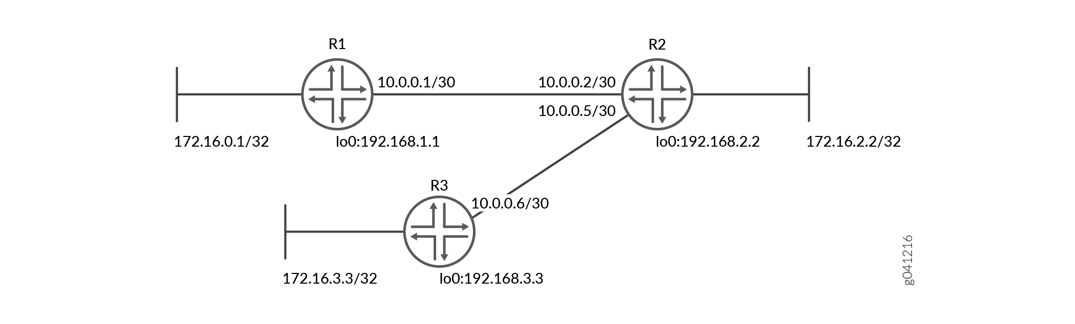
CLI Quick Configuration shows the configuration for all of the devices in Figure 1. The section #d14e74__d14e195 describes the steps on Device R1.
Topology
Configuration
Procedure
CLI Quick Configuration
To quickly configure this
example, copy the following commands, paste them into a text file,
remove any line breaks, change any details necessary to match your
network configuration, copy and paste the commands into the CLI at
the [edit] hierarchy level, and then enter commit from
configuration mode.
Device R1
set interfaces fe-1/2/0 unit 1 family inet address 10.0.0.1/30
set interfaces lo0 unit 1 family inet address 172.16.0.1/32
set interfaces lo0 unit 1 family inet address 192.168.1.1/32
set protocols rip group rip-group export advertise-routes-through-rip
set protocols rip group rip-group neighbor fe-1/2/0.1
set policy-options policy-statement advertise-routes-through-rip term 1 from protocol direct
set policy-options policy-statement advertise-routes-through-rip term 1 from protocol rip
set policy-options policy-statement advertise-routes-through-rip term 1 then accept
Device R2
set interfaces fe-1/2/0 unit 2 family inet address 10.0.0.2/30
set interfaces fe-1/2/1 unit 5 family inet address 10.0.0.5/30
set interfaces lo0 unit 2 family inet address 192.168.2.2/32
set interfaces lo0 unit 2 family inet address 172.16.2.2/32
set protocols rip group rip-group export advertise-routes-through-rip
set protocols rip group rip-group neighbor fe-1/2/0.2
set protocols rip group rip-group neighbor fe-1/2/1.5
set policy-options policy-statement advertise-routes-through-rip term 1 from protocol direct
set policy-options policy-statement advertise-routes-through-rip term 1 from protocol rip
set policy-options policy-statement advertise-routes-through-rip term 1 then accept
Device R3
set interfaces fe-1/2/0 unit 6 family inet address 10.0.0.6/30
set interfaces lo0 unit 3 family inet address 192.168.3.3/32
set interfaces lo0 unit 3 family inet address 172.16.3.3/32
set protocols rip group rip-group export advertise-routes-through-rip
set protocols rip group rip-group neighbor fe-1/2/0.6
set policy-options policy-statement advertise-routes-through-rip term 1 from protocol direct
set policy-options policy-statement advertise-routes-through-rip term 1 from protocol rip
set policy-options policy-statement advertise-routes-through-rip term 1 then accept
Step-by-Step Procedure
The following example requires you to navigate various levels in the configuration hierarchy. For information about navigating the CLI, see Using the CLI Editor in Configuration Mode in the CLI User Guide.
To configure a basic RIP network:
Configure the network interfaces.
This example shows multiple loopback interface addresses to simulate attached networks.
[edit interfaces]
user@R1# set fe-1/2/0 unit 1 family inet address 10.0.0.1/30
user@R1# set lo0 unit 1 family inet address 172.16.0.1/32
user@R1# set lo0 unit 1 family inet address 192.168.1.1/32
Create the RIP group and add the interface.
To configure RIP in Junos OS, you must configure a group that contains the interfaces on which RIP is enabled. You do not need to enable RIP on the loopback interface.
[edit protocols rip group rip-group]
user@R1# set neighbor fe-1/2/0.1
Create the routing policy to advertise both direct and RIP-learned routes.
[edit policy-options policy-statement advertise-routes-through-rip term 1]
user@R1# set from protocol direct
user@R1# set from protocol rip
user@R1# set then accept
Apply the routing policy.
In Junos OS, you can only apply RIP export policies at the group level.
[edit protocols rip group rip-group]
user@R1# set export advertise-routes-through-rip
Results
From configuration mode, confirm your configuration
by entering the show interfaces, show protocols, and show policy-options commands. If the output does
not display the intended configuration, repeat the configuration instructions
in this example to correct it.
user@R1# show interfaces
fe-1/2/0 {
    unit 1 {
        family inet {
            address 10.0.0.1/30;
        }
    }
}
lo0 {
    unit 1 {
        family inet {
            address 172.16.0.1/32;
            address 192.168.1.1/32;
        }
    }
}
user@R1# show protocols
rip {
    group rip-group {
        export advertise-routes-through-rip;
        neighbor fe-1/2/0.1;
    }
}
user@R1# show policy-options
policy-statement advertise-routes-through-rip {
    term 1 {
        from protocol [ direct rip ];
        then accept;
    }
}
If you are done configuring the device, enter commit from configuration mode.
Verification
Confirm that the configuration is working properly.
- Checking the Routing Table
- Looking at the Routes That Device R1 Is Advertising to Device R2
- Looking at the Routes That Device R1 Is Receiving from Device R2
- Verifying the RIP-Enabled Interfaces
- Verifying the Exchange of RIP Messages
- Verifying Reachability of All Hosts in the RIP Network
Checking the Routing Table
Purpose
Verify that the routing table is populated with the expected routes..
Action
From operational mode, enter the show route protocol
rip command.
user@R1> show route protocol rip
inet.0: 10 destinations, 10 routes (10 active, 0 holddown, 0 hidden)
+ = Active Route, - = Last Active, * = Both

10.0.0.4/30        *[RIP/100] 00:59:15, metric 2, tag 0
                    > to 10.0.0.2 via fe-1/2/0.1
172.16.2.2/32      *[RIP/100] 02:52:48, metric 2, tag 0
                    > to 10.0.0.2 via fe-1/2/0.1
172.16.3.3/32      *[RIP/100] 00:45:05, metric 3, tag 0
                    > to 10.0.0.2 via fe-1/2/0.1
192.168.2.2/32     *[RIP/100] 02:52:48, metric 2, tag 0
                    > to 10.0.0.2 via fe-1/2/0.1
192.168.3.3/32     *[RIP/100] 00:45:05, metric 3, tag 0
                    > to 10.0.0.2 via fe-1/2/0.1
224.0.0.9/32       *[RIP/100] 00:45:09, metric 1
                         MultiRecv
Meaning
The output shows that the routes have been learned from Device R2 and Device R3.
If you were to delete the from protocol rip condition in the routing policy on Device R2, the remote routes from Device R3 would not be learned on Device R1.
Looking at the Routes That Device R1 Is Advertising to Device R2
Purpose
Verify that Device R1 is sending the expected routes.
Action
From operational mode, enter the show route advertising-protocol
rip command.
user@R1> show route advertising-protocol rip 10.0.0.1
inet.0: 10 destinations, 10 routes (10 active, 0 holddown, 0 hidden)
+ = Active Route, - = Last Active, * = Both

172.16.0.1/32      *[Direct/0] 05:18:26
                    >    via lo0.1
192.168.1.1/32     *[Direct/0] 05:18:25
                    >    via lo0.1
Meaning
Device R1 is sending routes to its directly connected networks.
Looking at the Routes That Device R1 Is Receiving from Device R2
Purpose
Verify that Device R1 is receiving the expected routes.
Action
From operational mode, enter the show route receive-protocol
rip command.
user@R1> show route receive-protocol rip 10.0.0.2
inet.0: 10 destinations, 10 routes (10 active, 0 holddown, 0 hidden)
+ = Active Route, - = Last Active, * = Both

10.0.0.4/30        *[RIP/100] 02:31:22, metric 2, tag 0
                    > to 10.0.0.2 via fe-1/2/0.1
172.16.2.2/32      *[RIP/100] 04:24:55, metric 2, tag 0
                    > to 10.0.0.2 via fe-1/2/0.1
172.16.3.3/32      *[RIP/100] 02:17:12, metric 3, tag 0
                    > to 10.0.0.2 via fe-1/2/0.1
192.168.2.2/32     *[RIP/100] 04:24:55, metric 2, tag 0
                    > to 10.0.0.2 via fe-1/2/0.1
192.168.3.3/32     *[RIP/100] 02:17:12, metric 3, tag 0
                    > to 10.0.0.2 via fe-1/2/0.1
Meaning
Device R1 is receiving from Device R2 all of Device R2’s directly connected networks. Device R1 is also receiving from Device R2 all of Device R3’s directly connected networks, which Device R2 learned from Device R3 through RIP.
Verifying the RIP-Enabled Interfaces
Purpose
Verify that all RIP-enabled Interfaces are available and active.
Action
From operational mode, enter the show rip neighbor command.
user@R1> show rip neighbor
                  Local  Source          Destination     Send   Receive   In
Neighbor          State  Address         Address         Mode   Mode     Met
--------          -----  -------         -----------     ----   -------  ---
fe-1/2/0.1           Up 10.0.0.1        224.0.0.9        mcast  both     1
Meaning
The output shows that the RIP-enabled interface on Device R1 is operational.
In general for this command, the output shows a list of the RIP neighbors that are configured on the device. Verify the following information:
Each configured interface is present. Interfaces are listed in alphabetical order.
Each configured interface is up. The state of the interface is listed in the Local State column. A state of Up indicates that the link is passing RIP traffic. A state of Dn indicates that the link is not passing RIP traffic. In a point-to-point link, this state generally means that either the end point is not configured for RIP or the link is unavailable.
Verifying the Exchange of RIP Messages
Purpose
Verify that RIP messages are being sent and received on all RIP-enabled interfaces.
Action
From operational mode, enter the show rip statistics command.
user@R1> show rip statistics
RIPv2 info: port 520; holddown 120s.
    rts learned  rts held down  rqsts dropped  resps dropped
              5              0              0              0

fe-1/2/0.1:  5 routes learned; 2 routes advertised; timeout 180s; update interval 30s
Counter                         Total   Last 5 min  Last minute
-------                   -----------  -----------  -----------
Updates Sent                     2669           10            2
Triggered Updates Sent              2            0            0
Responses Sent                      0            0            0
Bad Messages                        0            0            0
RIPv1 Updates Received              0            0            0
RIPv1 Bad Route Entries             0            0            0
RIPv1 Updates Ignored               0            0            0
RIPv2 Updates Received           2675           11            2
RIPv2 Bad Route Entries             0            0            0
RIPv2 Updates Ignored               0            0            0
Authentication Failures             0            0            0
RIP Requests Received               0            0            0
RIP Requests Ignored                0            0            0
none                                0            0            0
Meaning
The output shows the number of RIP routes learned. It also shows the number of RIP updates sent and received on the RIP-enabled interfaces. Verify the following information:
The number of RIP routes learned matches the number of expected routes learned. Subnets learned by direct connectivity through an outgoing interface are not listed as RIP routes.
RIP updates are being sent on each RIP-enabled interface. If no updates are being sent, the routing policy might not be configured to export routes.
RIP updates are being received on each RIP-enabled interface. If no updates are being received, the routing policy might not be configured to export routes on the host connected to that subnet. The lack of updates might also indicate an authentication error.
Verifying Reachability of All Hosts in the RIP Network
Purpose
Use the traceroute command on each loopback
address in the network to verify that all hosts in the RIP network
are reachable from each Juniper Networks device.
Action
From operational mode, enter the traceroute command.
user@R1> traceroute 192.168.3.3
traceroute to 192.168.3.3 (192.168.3.3), 30 hops max, 40 byte packets
 1  10.0.0.2 (10.0.0.2)  1.094 ms  1.028 ms  0.957 ms
 2  192.168.3.3 (192.168.3.3)  1.344 ms  2.245 ms  2.125 ms
Meaning
Each numbered row in the output indicates a routing hop in the path to the host. The three-time increments indicate the round-trip time (RTT) between the device and the hop for each traceroute packet.
To ensure that the RIP network is healthy, verify the following information:
The final hop in the list is the host you want to reach.
The number of expected hops to the host matches the number of hops in the traceroute output. The appearance of more hops than expected in the output indicates that a network segment is probably unreachable. It might also indicate that the incoming or outgoing metric on one or more hosts has been set unexpectedly.