ON THIS PAGE
Understanding Junos Node Slicing
Junos Node Slicing Overview
Junos node slicing enables service providers and large enterprises to create a network infrastructure that consolidates multiple routing functions into a single physical device. It helps in hosting multiple services on a single physical infrastructure while avoiding the operational complexity involved. It also maintains operational, functional, and administrative separation of the functions hosted on the device.
Using Junos node slicing, you can create multiple partitions in a single physical MX Series router. These partitions are referred to as guest network functions (GNFs). Each GNF behaves as an independent router, with its own dedicated control plane, data plane, and management plane. This enables you to run multiple services on a single converged MX Series router, while still maintaining operational isolation between them. You can leverage the same physical device to create parallel partitions that do not share the control plane or the forwarding plane, but only share the same chassis, space, and power.
You can also send traffic between GNFs through the switch fabric by using an abstracted fabric
(af) interface, a pseudo interface that behaves as a first class
Ethernet interface. An abstracted fabric interface facilitates routing control, data,
and management traffic between GNFs.
Junos node slicing offers two models - an external server model and an in-chassis model. In the external server model, the GNFs are hosted on a pair of industry-standard x86 servers. For the in-chassis model, the GNFs are hosted on the Routing Engines of the MX Series router itself.
Junos node slicing supports multiversion software compatibility, thereby allowing the GNFs to be independently upgraded.
Benefits of Junos Node Slicing
Converged network—With Junos node slicing, service providers can consolidate multiple network services, such as video edge and voice edge, into a single physical router, while still maintaining operational separation between them. You can achieve both horizontal and vertical convergence. Horizontal convergence consolidates router functions of the same layer to a single router, while vertical convergence collapses router functions of different layers into a single router.
Improved scalability—Focusing on virtual routing partitions, instead of physical devices, improves the programmability and scalability of the network, enabling service providers and enterprises to respond to infrastructure requirements without having to buy additional hardware.
Easy risk management—Though multiple network functions converge on a single chassis, all the functions run independently, benefiting from operational, functional, and administrative separation. Partitioning a physical system, such as Broadband Network Gateway (BNG), into multiple independent logical instances ensures that failures are isolated. The partitions do not share the control plane or the forwarding plane, but only share the same chassis, space, and power. This means failure in one partition does not cause any widespread service outage.
Reduced network costs—Junos node slicing enables interconnection of GNFs through internal switching fabrics, which leverages abstracted fabric (
af) interface, a pseudo interface that represents a first class Ethernet interface behavior. Withafinterface in place, companies no longer need to depend on physical interfaces to connect GNFs, resulting in significant savings.Reduced time-to-market for new services and capabilities—Each GNF can operate on a different Junos software version. This advantage enables companies to evolve each GNF at its own pace. If a new service or a feature needs to be deployed on a certain GNF, and it requires a new software release, only the GNF involved requires an update. Additionally, with the increased agility, Junos node slicing enables service providers and enterprises to introduce highly flexible Everything-as-a-service business model to rapidly respond to ever-changing market conditions.
Components of Junos Node Slicing
Junos node slicing enables you to partition a single MX Series router to make it appear as multiple, independent routers. Each partition has its own Junos OS control plane, which runs as a virtual machine (VM), and a dedicated set of line cards. Each partition is called a guest network function (GNF).
The MX Series router functions as the base system (BSYS). The BSYS owns all the physical components of the router, including the line cards and the switching fabric. The BSYS assigns line cards to GNFs.
The Juniper Device Manager (JDM) software orchestrates the GNF VMs. In JDM, a GNF VM is referred to as a virtual network function (VNF). A GNF thus comprises a VNF and a set of line cards.
Through configuration at the BSYS, you can assign line cards of the chassis to different GNFs. Additionally, depending on the linecard type, you can even assign sets of PFEs within a linecard to different GNFs. See Sub Line Card Overview for details.
Junos node slicing supports two models:
-
External server model
-
In-chassis model
In the external server model, JDM and VNFs are hosted on a pair of external industry standard x86 servers.
Figure 1 shows three GNFs with their dedicated line cards running on an external server.
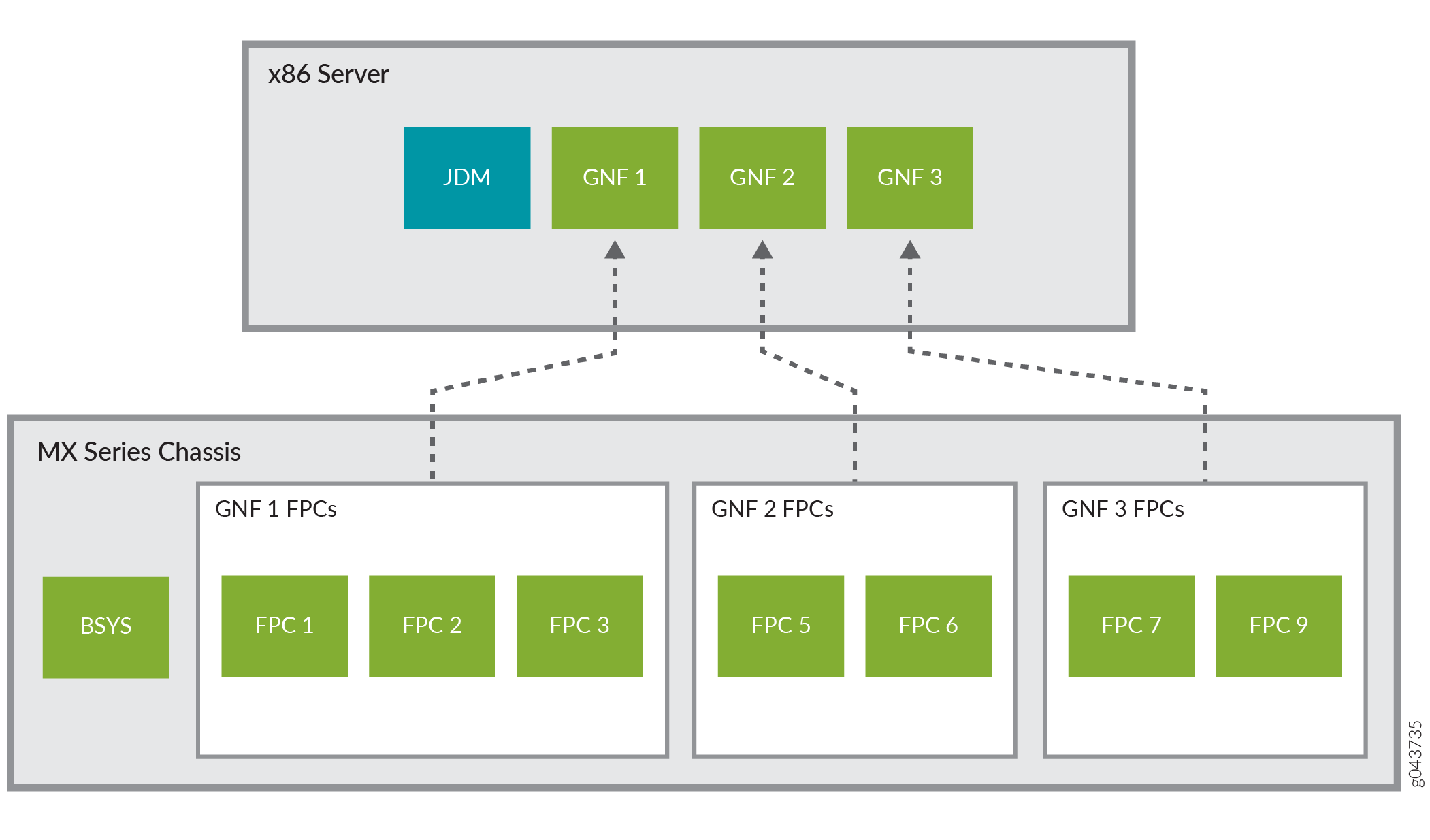
See Connecting the Servers and the Router for information about how to connect an MX Series router to a pair of external x86 servers.
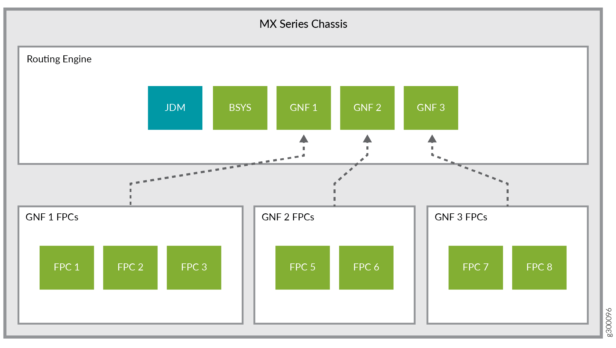
In the in-chassis model, all components (JDM, BSYS, as well as GNFs) run within the Routing Engine of the MX Series router. See Figure 2.
Base System (BSYS)
In Junos node slicing, the MX Series router functions as the base system (BSYS). The BSYS owns
all the physical components of the router, including
all line cards and fabric. Through Junos OS
configuration at the BSYS, you can assign line cards
to GNFs and define abstracted fabric
(af) interfaces between GNFs. The
BSYS software runs on a pair of redundant Routing
Engines of the MX Series router.
Guest Network Function (GNF)
A guest network function (GNF) logically owns the line cards assigned to it by the base system (BSYS), and maintains the forwarding state of the line cards. You can configure multiple GNFs on an MX Series router (see Configuring Guest Network Functions). The Junos OS control plane of each GNF runs as a virtual machine (VM). The Juniper Device Manager (JDM) software orchestrates the GNF VMs. In the JDM context, the GNFs are referred to as virtual network functions (VNF).
A GNF is equivalent to a standalone router. GNFs are configured and administered independently, and are operationally isolated from each other.
Creating a GNF requires two sets of configurations, one to be performed at the BSYS, and the other at the JDM.
A GNF is defined by an ID. This ID must be the same at the BSYS and JDM.
The BSYS part of the GNF configuration comprises giving it an ID and a set of line cards.
The JDM part of the GNF configuration comprises specifying the following attributes:
-
A VNF name.
-
A GNF ID. This ID must be the same as the GNF ID used at the BSYS.
-
The MX Series platform type (for the external server model).
-
A Junos OS image to be used for the VNF.
-
The VNF server resource template.
The server resource template defines the number of dedicated (physical) CPU cores and the size of DRAM to be assigned to a GNF. For a list of predefined server resource templates available for GNFs, see the Server Hardware Resource Requirements (Per GNF) section in Minimum Hardware and Software Requirements for Junos Node Slicing.
After a GNF is configured, you can access it by connecting to the virtual console port of the GNF. Using the Junos OS CLI at the GNF, you can then configure the GNF system properties such as hostname and management IP address, and subsequently access it through its management port.
Juniper Device Manager (JDM)
The Juniper Device Manager (JDM), a virtualized Linux container, enables provisioning and management of the GNF VMs.
JDM supports Junos OS-like CLI, NETCONF for configuration and management and SNMP for monitoring.
In the in-chassis model, JDM does not support SNMP.
A JDM instance is hosted on each of the x86 servers in the external server model, and on each Routing Engine for the in-chassis model. The JDM instances are typically configured as peers that synchronize the GNF configurations: when a GNF VM is created on one server, its backup VM is automatically created on the other server or Routing Engine.
An IP address and an administrator account need to be configured on the JDM. After these are configured, you can directly log in to the JDM.
See Also
Abstracted Fabric Interface
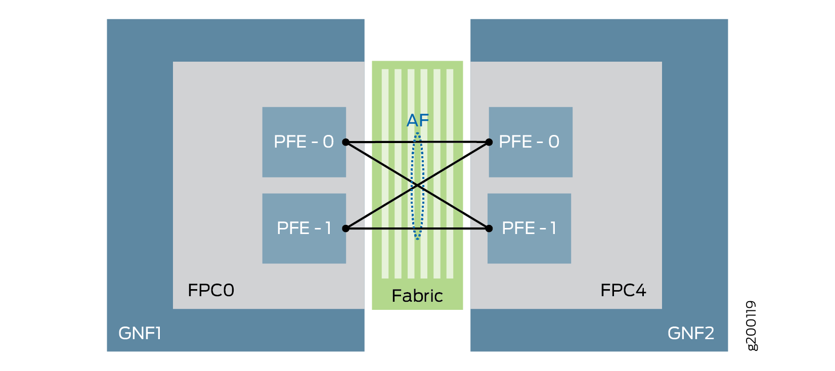
Abstracted fabric (af) interface is a pseudo interface that represents a first
class Ethernet interface behavior. An af interface facilitates routing
control and management traffic between guest network functions (GNFs) through the switch
fabric. An af interface is created on a GNF to communicate with its
peer GNF when the two GNFs are configured to be connected to each other. Abstracted
fabric interfaces must be created at BSYS. The bandwidth of the af
interfaces changes dynamically based on the insertion or reachability of the remote line
card/MPC. Because the fabric is the communication medium between GNFs,
af interfaces are considered to be the equivalent WAN interfaces.
See Figure 3.
- Understanding Abstracted Fabric Interface Bandwidth
- Features Supported on Abstracted Fabric Interfaces
- Abstracted Fabric Interface Restrictions
Understanding Abstracted Fabric Interface Bandwidth
An abstracted fabric (af) interface connects two GNFs through the fabric and
aggregates all the Packet Forwarding Engines (PFEs) that connect the two GNFs. An
af interface can leverage the sum of the bandwidth of each
Packet Forwarding Engine belonging to the af interface.
For example, if GNF1 has one MPC8 (which has four Packet Forwarding
Engines with 240 Gbps capacity each), and GNF1 is connected with
GNF2 and GNF3 using af interfaces (af1 and af2), the maximum af interface capacity on GNF1 would be 4x240 Gbps = 960 Gbps.
GNF1—af1——GNF2
GNF1—af2——GNF3
Here, af1 and af2 share the 960 Gbps capacity.
For information on the bandwidth supported on each MPC, see Table 1.
Features Supported on Abstracted Fabric Interfaces
Abstracted fabric interfaces support the following features:
-
Unified in-service software upgrade (ISSU)
-
Hyper mode configuration at the BSYS level (starting in Junos OS Release 19.3R2). This feature is supported on MPC6E, MPC8E, MPC9E, and MPC11E line cards.
Note:-
You cannot have different hyper mode configurations for individual GNFs as they inherit the configuration from the BSYS.
-
The MX2020 and MX2010 routers with SFB3 come up in hyper mode by default. If you require hyper mode to be disabled at any GNF, you must configure it at the BSYS, and it will apply to all GNFs of that chassis.
-
-
Load balancing based on the remote GNF line cards present
-
Class of service (CoS) support:
-
Inet-precedence classifier and rewrite
-
DSCP classifier and rewrite
-
MPLS EXP classifier and rewrite
-
DSCP v6 classifier and rewrite for IP v6 traffic
-
-
Support for OSPF, IS-IS, BGP, OSPFv3 protocols, and L3VPN
Note:The non-
afinterfaces support all the protocols that work on Junos OS. -
BFD for BGP, IS-IS, and OSPF starting in Junos OS Release 24.2R1.
-
Multicast forwarding
-
Graceful Routing Engine switchover (GRES)
-
MPLS applications where the
afinterface acts as a core interface (L3VPN, VPLS, L2VPN, L2CKT, EVPN, and IP over MPLS) -
The following protocol families are supported:
-
IPv4 Forwarding
-
IPv6 Forwarding
-
MPLS
-
ISO
-
CCC
-
-
Junos Telemetry Interface (JTI) sensor support
-
Starting in Junos OS Release 19.1R1, guest network functions (GNFs) support Ethernet VPNs (EVPN) with Virtual Extensible LAN protocol (VXLAN) encapsulation. This support is available with non-
af(that is, physical) interface andafinterface as the core facing interface. This support is not available for the MPC11E line card. -
With the
afinterface configuration, GNFs supportaf-capable MPCs. Table 1 lists theaf-capable MPCs, the number of PFEs supported per MPC, and the bandwidth supported per MPC.Table 1: Supported Abstracted Fabric-capable MPCs MPC
Initial Release
Number of PFEs
Total Bandwidth
MPC7E-MRATE
17.4R1
2
480G (240*2)
MPC7E-10G
17.4R1
2
480G (240*2)
MX2K-MPC8E
17.4R1
4
960G (240*4)
MX2K-MPC9E
17.4R1
4
1.6T (400*4)
MPC2E
19.1R1
2
80 (40*2)
MPC2E NG
17.4R1
1
80G
MPC2E NG Q
17.4R1
1
80G
MPC3E
19.1R1
1
130G
MPC3E NG
17.4R1
1
130G
MPC3E NG Q
17.4R1
1
130G
32x10GE MPC4E
19.1R1
2
260G (130*2)
2x100GE + 8x10GE MPC4E
19.1R1
2
260G (130*2)
MPC5E-40G10G
18.3R1
2
240G (120*2)
MPC5EQ-40G10G
18.3R1
2
240G (120*2)
MPC5E-40G100G
18.3R1
2
240G (120*2)
MPC5EQ-40G100G
18.3R1
2
240G (120*2)
MX2K-MPC6E
18.3R1
4
520G (130*4)
Multiservices MPC (MS-MPC)
19.1R1
1
120G
16x10GE MPC
19.1R1
4
160G (40*4)
MX2K-MPC11E
19.3R2
8
4T (500G*8)
We recommend that you set the MTU settings on the af interface
to align to the maximum allowed value on the XE/GE interfaces. This ensures
minimal or no fragmentation of packets over the af interface.
Abstracted Fabric Interface Restrictions
The following are the current restrictions of abstracted fabric interfaces:
-
Configurations such as single endpoint
afinterface,afinterface-to-GNF mapping mismatch or multipleafinterfaces mapping to same remote GNF are not checked during commit on the BSYS. Ensure that you have the correct configurations. -
Bandwidth allocation is static, based on the MPC type.
-
There can be minimal traffic drops (both transit and host) during the offline/restart of an MPC hosted on a remote GNF.
-
Interoperability between MPCs that are
af-capable and the MPCs that are notaf-capable is not supported.
See Also
Optimizing Fabric Path for Abstracted Fabric Interface
You can optimize the traffic flowing over the abstracted fabric (af) interfaces between two guest network functions (GNFs), by configuring a fabric path optimization mode. This feature reduces fabric bandwidth consumption by preventing any additional fabric hop (switching of traffic flows from one Packet Forwarding Engine to another) before the packets eventually reach the destination Packet Forwarding Engine. Fabric path optimization, supported on MX2008, MX2010, and MX2020 with MPC9E and MX2K-MPC11E, prevents only a single additional traffic hop that results from abstracted fabric interface load balancing.
You can configure one of the following fabric path optimization modes:
monitor—If you configure this mode, the peer GNF monitors the traffic flow and sends information to the source GNF about the Packet Forwarding Engine to which the traffic is being forwarded currently and the desired Packet Forwarding Engine that could provide an optimized traffic path. In this mode, the source GNF does not forward the traffic towards the desired Packet Forwarding Engine.optimize—If you configure this mode, the peer GNF monitors the traffic flow and sends information to the source GNF about the Packet Forwarding Engine to which the traffic is being forwarded currently and the desired Packet Forwarding Engine that could provide an optimized traffic path. The source GNF then forwards the traffic towards the desired Packet Forwarding Engine.
To configure a fabric path optimization mode, use the following CLI commands at BSYS.
user@router#set chassis network-slices guest-network-functions gnf id af-name collapsed-forward (monitor | optimize)user@router#commit
After configuring fabric path optimization, you can use the
command show interfaces af-interface-name in GNF to view the number of packets that are currently flowing
on the optimal / non-optimal path.
See Also
Choosing Between External Server Model and In-Chassis Model
The external server model allows you to configure more instances of GNFs with higher scale, since you can choose a server of sufficient capacity to match GNF requirements. With the in-chassis model, the number of GNFs that can be configured is a function of the scale requirements of the constituent GNFs and the overall capacity of the Routing Engine.
The external server and in-chassis models of Junos node slicing are mutually exclusive. An MX Series router can be configured to operate in only one of these models at one time.
Primary-role Behavior of BSYS and GNF
The following sections address the primary-role behavior of BSYS and GNF in the context of Routing Engine redundancy.
Figure 4 shows the primary-role behavior of GNF and BSYS with Routing Engine redundancy.
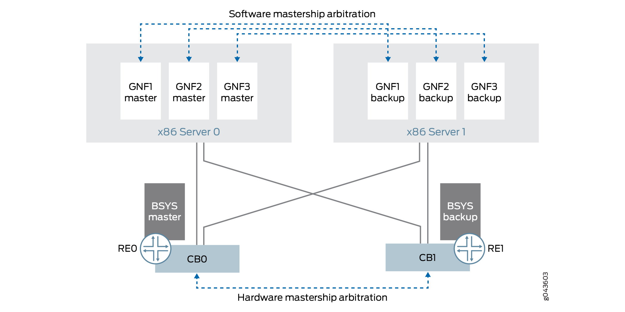
BSYS Primary Role
The BSYS Routing Engine primary-role arbitration behavior is identical to that of Routing Engines on MX Series routers.
GNF Primary Role
The GNF VM primary-role arbitration behavior is similar to that
of MX Series Routing Engines. Each GNF runs as a primary-backup pair
of VMs. A GNF VM that runs on server0 (or re0 for in-chassis) is equivalent to Routing Engine slot 0 of an MX
Series router, and the GNF VM that runs on server1 (or re1 for in-chassis) is equivalent to Routing Engine slot 1
of an MX Series router.
The GNF primary role is independent of the BSYS primary role and that of other GNFs. The GNF primary role arbitration is done through Junos OS. Under connectivity failure conditions, GNF primary role is handled conservatively.
The GNF primary-role model is the same for both external server and in-chassis models.
As with the MX Series Routing Engines, you must configure graceful Routing Engine switchover (GRES) at each GNF. This is a prerequisite for the backup GNF VM to automatically take over the primary role when the primary GNF VM fails or is rebooted.
Junos Node Slicing Administrator Roles
The following administrator roles enable you to carry out the node slicing tasks:
BSYS administrator—Responsible for the physical chassis, as well as for GNF provisioning (assignment of line cards to GNFs). Junos OS CLI commands are available for these tasks.
GNF administrator—Responsible for configuration, operation, and management of Junos OS at the GNF. All regular Junos OS CLI commands are available to the GNF administrator for these tasks.
JDM administrator—Responsible for the JDM server port configuration (for the external server model), and for the provisioning and life-cycle management of the GNF VMs (VNFs). JDM CLI commands are available for these tasks.
Sub Line Card Overview
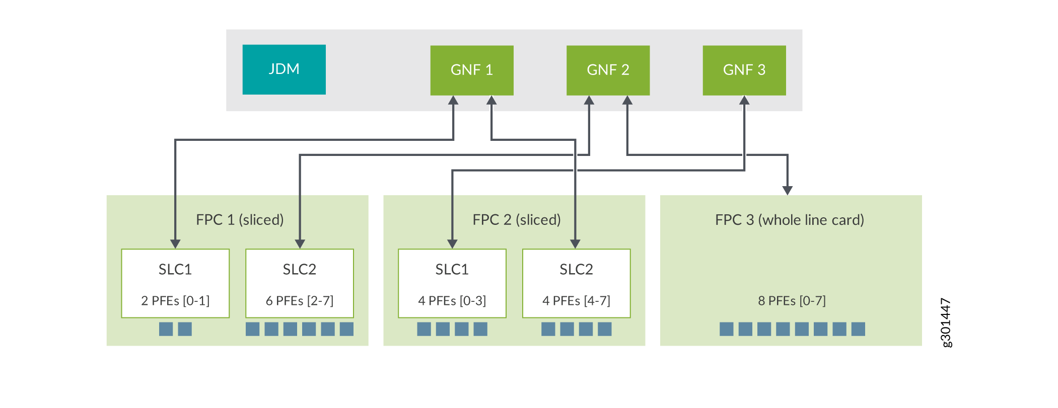
In Junos node slicing, each GNF comprises a set of line cards (FPCs). By default, the finest granularity provided by a GNF is at the line card level, because each GNF is assigned whole line cards (that is, the complete set of Packet Forwarding Engines in each line card). With the sub line card (SLC) feature, you can define even finer granularity of partitioning, by assigning subsets of Packet Forwarding Engines in a single line card to different GNFs.
Such user-defined subsets of Packet Forwarding Engines in a line card are referred to as sub line cards (SLCs). Operationally, SLCs function like independent line cards.
When you slice a line card, every SLC of that line card must be assigned to a different GNF.
You can assign SLCs from multiple line cards to the same GNF.
In a Junos node slicing setup with the SLC feature, a GNF can comprise a set of whole line cards as well as a set of slices (SLCs) of line cards, providing a higher level of flexibility.
When a line card is sliced, two types of software instances run on that line card - a single base line card (BLC) instance and multiple SLC instances (as many as the number of slices of that line card). Currently, the SLC capability is available only on the MPC11E, which supports two SLCs. The BLC instance is responsible for managing hardware common to all SLCs of that line card, while each SLC instance is responsible for managing the set of Packet Forwarding Engines exclusively assigned to it. The BLC instance runs the Junos software of the BSYS, while each SLC instance runs the Junos software of its associated GNF.
SLCs support abstracted fabric interface and collapsed forwarding (see Optimizing Fabric Path for Abstracted Fabric Interface). You can use the
show interface af-interface-name
command to view the
load balance statistics of the remote FPC slice-specific Packet Forwarding Engines. See show interfaces (Abstracted Fabric) for details.
The SLC capability is available only on the MPC11E (model number: MX2K-MPC11E).
Line Card Resources for SLCs
An SLC or a slice of a line card defines the set of Packet Forwarding Engines (of that line card) that must operate together. Packet Forwarding Engines in a line card are identified by numeric IDs. If a line card has ‘n’ Packet Forwarding Engines, the individual Packet Forwarding Engines are numbered 0 to (n-1). In addition, CPU cores and DRAM on the control board of the line card must also be divided and allocated to the slice. To define an SLC, then, is to define the following line card resources to be dedicated to that SLC:
-
A Packet Forwarding Engine range
-
The number of CPU cores on the control board of the line card
-
The size of DRAM (in GB) on the control board of the line card
A certain amount of the DRAM is automatically reserved for the BLC instance on that line card, and the remainder is available for SLC instances.
Every SLC is identified by a numeric ID, assigned by the user.
When a line card is sliced, the resource partitions for every slice on that line card must be completely defined.
MPC11E Line Card Resources for SLCs
An MPC11E line card has:
-
8 Packet Forwarding Engines
-
8 CPU cores on the control board
-
32 GB of DRAM on the control board
5 GB of DRAM is automatically reserved for BLC use, 1 GB of DRAM is allocated to the line card host, and the remaining 26 GB is available for SLC slices.
An MPC11E is capable of supporting two SLCs.
The Table 2 defines two types of resource allocation profiles supported by an MPC11E for the two SLCs, referred to here as SLC1 and SLC2.
In the symmetric profile, the Packet Forwarding Engines and other line card resources are distributed evenly between the slices. In the asymmetric profile, only the specified line card resource combinations shown in Table 2 are supported.
You can configure the following SLC profiles, based on how the Packet Forwarding Engines [0-7] are split between the two SLCs:
-
Packet Forwarding Engines 0-3 for one SLC, and 4-7 for the other SLC (symmetric profile)
-
Packet Forwarding Engines 0-1 for one SLC, and 2-7 for the other SLC (asymmetric profile)
-
Packet Forwarding Engines 0-5 for one SLC and 6-7 for the other SLC (asymmetric profile)
In the asymmetric profile, you can assign either 9 GB or 17 GB of DRAM to an SLC. Since all the line card resources must be fully assigned, and the total DRAM available for SLCs is 26 GB, assigning 9 GB of DRAM to an SLC requires that the remaining 17 GB must be assigned to the other SLC.
|
Symmetric Profile |
Asymmetric Profile |
|||
|---|---|---|---|---|
|
Resource Type |
SLC1 |
SLC2 |
SLC1 |
SLC2 |
|
Packet Forwarding Engine |
4 |
4 |
2 |
6 |
|
DRAM |
13 GB |
13 GB |
17 GB/9 GB |
9 GB/17 GB |
|
CPU |
4 |
4 |
4 |
4 |
See also: Configuring Sub Line Cards and Assigning Them to GNFs and Managing Sub Line Cards.
Multiversion Software Interoperability Overview
Starting from Junos OS Release 17.4R1, Junos node slicing supports multiversion software compatibility, enabling the BSYS to interoperate with a guest network function (GNF) which runs a Junos OS version that is higher than the software version of the BSYS. This feature supports a range of up to two versions between GNF and BSYS. That is, the GNF software can be two versions higher than the BSYS software. Both BSYS and GNF must meet a minimum version requirement of Junos OS Release 17.4R1.
The restrictions in multiversion support are also applicable to the unified ISSU upgrade process.
While JDM software versioning does not have a similar restriction with respect to the GNF or BSYS software versions, we recommend that you regularly update the JDM software. A JDM upgrade does not affect any of the running GNFs.
Next Gen Services on Junos node slicing
Junos node slicing supports MX-SPC3
Services Card, a security services card that provides
additional processing power to run the Next Gen Services on the MX
platforms. You can enable Next Gen Services at guest network function
(GNF), by using the CLI request
system enable unified-services at GNF. To support
an MX-SPC3, a GNF must have a line card associated with it.
In a Junos node slicing setup, you can use both MX-SPC3 and
MS-MPC on the same chassis but on different GNF Routing Engines. If
you have enabled Next Gen Services at GNF, by using request system
enable unified-services, the MX-SPC3 comes online. If you have
not enabled Next Gen Services, the MS-MPC comes online.
The software installation or upgrade of an MX-SPC3 card happens when you install or upgrade the associated GNF Routing Engine.
The MX-SPC3 does not support abstracted fabric interfaces. Therefore, a GNF that has an MX-SPC3 card linked to it must also have a line card associated with it.
Comparing Junos Node Slicing with Logical Systems
Junos node slicing is a layer below logical systems in Junos. Both technologies have some overlapping capabilities but differ in other aspects. With Junos node slicing, complete line cards, and therefore, physical interfaces, are assigned to a GNF, while with logical systems, a single physical interface itself can be shared across different logical systems, since multiple logical interfaces defined over a physical interface can all be assigned to separate logical systems. This means, logical systems allow finer granularity of sharing than Junos node slicing. But all logical systems share a single Junos kernel, thus necessarily running the same Junos version, besides having to share the Routing Engine and line card physical resources such as CPU, memory and storage. With Junos node slicing, each GNF gets its own equivalent of a pair of Routing Engines, as also line cards dedicated to that GNF, so the GNFs do not share most physical resources – they only share the chassis and switch fabric. GNFs, unlike logical systems, can be independently upgraded and administered like a MX standalone router.
Junos node slicing is a technology that complements, and even augments logical systems, since a GNF can itself have multiple logical systems within it. Where physical isolation, guaranteed resources and complete administrative isolation is paramount, Junos node slicing would be a better match. And where fine granularity of sharing, down to the logical interface level, is paramount, a logical system would be the better match.
Licensing for Junos Node Slicing
Operating Junos node slicing requires licenses for the GNFs and abstracted fabric interfaces to be installed at the BSYS. Running a GNF without a license installed at the BSYS will result in the following syslog message and minor alarm:
CHASSISD_LICENSE_EVENT: License Network-Slices: Failed to get valid license('216') 'gnf-creation'
Minor alarm set, 1 Guest network functions creation for JUNOS requires a license.
Please contact Juniper Networks if you have queries pertaining to Junos node slicing licenses.